SECTION
MAINTENANCE AND REPAIR
ON-VEHICLE SERVICE
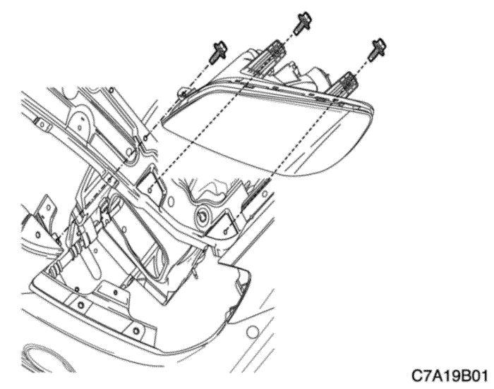


Headlamps
Removal Procedure
- Disconnect the negative battery cable.
- Remove the radiator grille upper cover.
- Remove the bolts and the headlamp assembly.


- Disconnect the headlamp assembly electrical connectors.
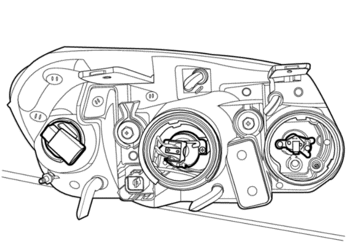


- Remove the cap that conceals the headlamp bulb.
- Disconnect the headlamp bulb electrical connectors.
- Remove the headlamp bulbs.


Installation Procedure
- Install the headlamp bulbs.
- Connect the headlamp bulb electrical connectors.
- Install the cap that conceals the headlamp bulbs.


- Connect the headlamp assembly electrical connectors.


- Install the headlamp assembly with the bolts.
Tighten
Tighten the headlamp assembly bolts to 7 N•m (62 lb-in).
- Install the radiator grille upper cover.
- Connect the negative battery cable.


Parking and Front Turn Signal Lamps
Removal Procedure
- Disconnect the negative battery cable.
- Remove the lamp. Refer to "Headlamp" in this section.
- Twist and remove the bulbs from the headlamp.


Installation Procedure
- Insert and twist to install the replacement bulb into the headlamp.
- Connect the electrical connector.
Notice : Dissimilar metals in direct contact with each other may corrode rapidly. Make sure to use the correct fasteners to prevent premature corrosion.
- Install the headlamp. Refer to "Headlamp" in this section.
- Connect the negative battery cable.


Rear Combination Lamps
Removal Procedure
- Disconnect the negative battery cable.
- Disconnect the electrical connectors.
- Remove the nuts and the lamp assembly.
- Remove any inoperative bulb.


Installation Procedure
- Install the replacement bulbs.
Notice : Dissimilar metals in direct contact with each other may corrode rapidly. Make sure to use the correct fasteners to prevent premature corrosion.
- Install the lamp assembly with the nuts.
Tighten
Tighten the rear combination lamp assembly nuts to 2.5 N•m (22 lb-in).
- Connect the electrical connectors.
- Connect the negative battery cable.
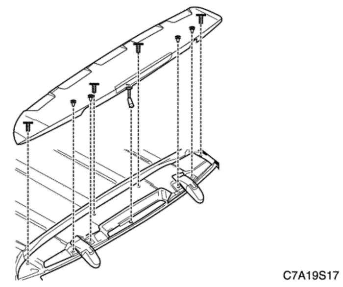


Center High-Mounted Stoplamp
Removal Procedure
- Disconnect the negative battery cable.
- Remove the liftgate upper applique. Refer to Section 9S, Body Rear End.
- Disconnect the electrical connector.
- Remove the CHMSL bulb.


Installation Procedure
- Install the replacement CHMSL bulb.
- Connect the electrical connector.
Notice : Dissimilar metals in direct contact with each other may corrode rapidly. Make sure to use the correct fasteners to prevent premature corrosion.
- Install the liftgate upper applique. Refer to Section 9S, Body Rear End.
- Connect the negative battery cable.
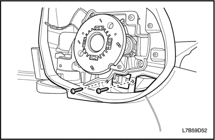


Side Turn Signal Lamps
Removal Procedure
- Disconnect the negative battery cable.
- Remove the outside rearview mirror glass. Refer to Section 9L, Glass and Mirror.
- Remove the screws and the side turn signal lamp assembly.
- Disconnect the electrical connector.


Installation Procedure
Notice : The side turn signal lamp assembly has no serviceable items. LED's are used to provide illumination. If any LED fails to function, the side turn signal lamp assembly must be replaced.
- Connect the electrical connector.
- Install the side turn signal lamp assembly with the screws.
- Install the outside rearview mirror glass. Refer to Section 9L, Glass and Mirror.
- Connect the negative battery cable.
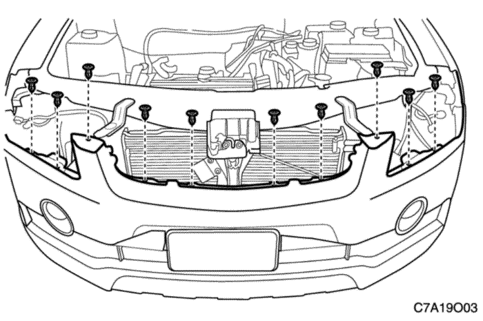


Fog Lamps
Removal Procedure
- Disconnect the negative battery cable.
- Remove the front bumper fascia. Refer to Section 9O, Bumpers and Fascias.
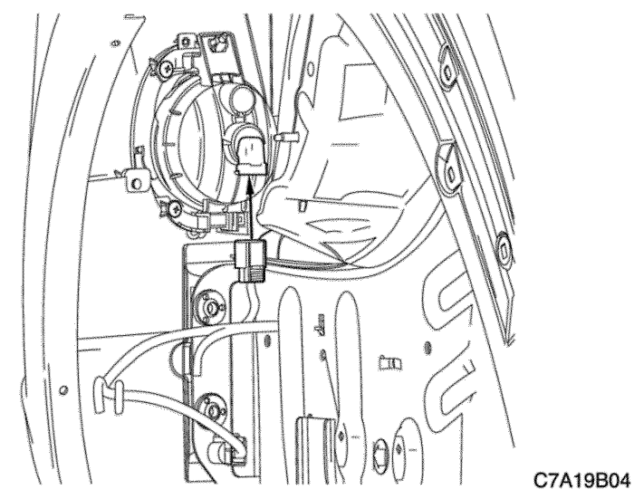


- Remove the screws that secure the fog lamp assembly.
- Disconnect the fog lamp assembly electrical connector.
- Remove the fog lamp assembly.
- Remove the bulb from the fog lamp assembly.


Installation Procedure
- Install the bulb into the fog lamp assembly.
Notice : Dissimilar metals in direct contact with each other may corrode rapidly. Make sure to use the correct fasteners to prevent premature corrosion.
- Install the fog lamp assembly with the screws.
- Connect the electrical connector.


- Install the front bumper fascia. Refer to Section 9O, Bumpers and Fascias.
- Connect the negative battery cable.


License Plate Lamps
Removal Procedure
- Disconnect the negative battery cable.
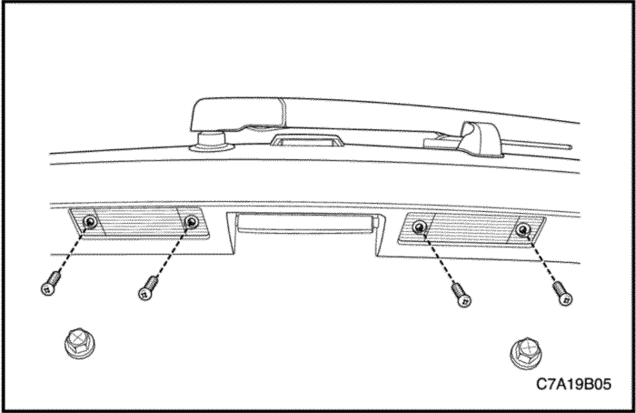
- Remove the screws and the license plate lamp assembly.
- Remove the bulb.


Installation Procedure
- Install the replacement bulb.
Notice : Dissimilar metals in direct contact with each other may corrode rapidly. Make sure to use the correct fasteners to prevent premature corrosion.
- Install the license plate lamp assembly with the screws.
Tighten
Tighten the license plate lamp assembly screws to 4 N•m (35 lb-in).
- Connect the negative battery cable.


Map Lamp
Removal Procedure
- Disconnect the negative battery cable.
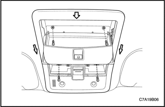
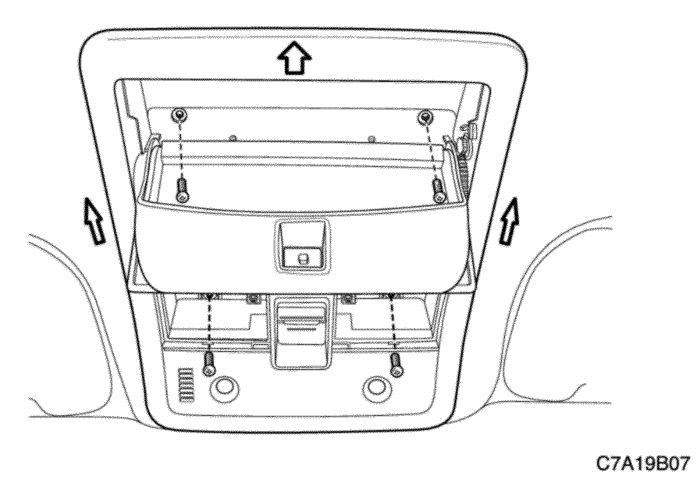
- Pry off the map lamp lens by inserting a screwdriver into the recess along the edge of the lens.
- Remove the screws and the map lamp housing from the headliner.
- Disconnect the electrical connector.
- Remove the bulb.


Installation Procedure
- Install the replacement bulb.
- Connect the electrical connector.
Notice : Dissimilar metals in direct contact with each other may corrode rapidly. Make sure to use the correct fasteners to prevent premature corrosion.
- Install the map lamp housing to the headliner with the screws.
Tighten
Tighten the map lamp housing screw to 2 N•m (18 lb-in).
- Press the map lamp lens onto the housing.
- Connect the negative battery cable.


Room Lamp
Removal Procedure
- Disconnect the negative battery cable.
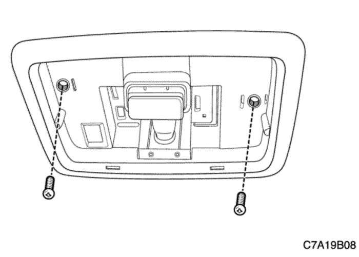
- Pry off the room lamp lens by inserting a screwdriver into the recess along the edge of the lens.
- Remove the screws and the room lamp housing from the headliner.
- Disconnect the electrical connector.
- Remove the bulb.


Installation Procedure
- Install the replacement bulb.
- Connect the electrical connector.
Notice : Dissimilar metals in direct contact with each other may corrode rapidly. Make sure to use the correct fasteners to prevent premature corrosion.
- Install the interior room lamp housing to the headliner with the screws.
Tighten
Tighten the room lamp housing screw to 2 N•m (18 lb-in).
- Press the room lamp lens onto the housing.
- Connect the negative battery cable.


Front Door Step Lamp
Removal Procedure
- Disconnect the negative battery cable.
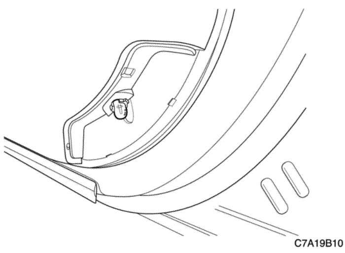
- Remove the front door step lamp lens cover.
- Remove the front door step lamp.
- Disconnect the electrical connector.


Installation Procedure
- Connect the electrical connector.
- Install the replacement front door step lamp bulb.
Notice : Dissimilar metals in direct contact with each other may corrode rapidly. Make sure to use the correct fasteners to prevent premature corrosion.
- Install the front door step lamp lens cover.
- Connect the negative battery cable.


Instrument Compartment Lamp
Removal Procedure
- Disconnect the negative battery cable.
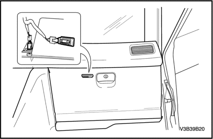
- Open the glove box.
- Remove the glove box lamp.
- Disconnect the electrical connector.


Installation Procedure
- Connect the electrical connector.
- Install the glove box lamp.
- Close the glove box.
- Connect the negative battery cable.
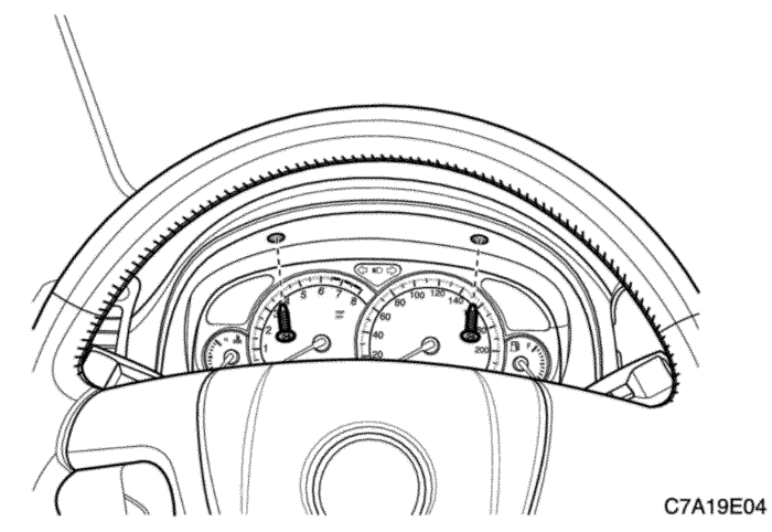


X-BCM
Removal Procedure
- Disconnect the negative battery cable.
- Remove the instrument cluster. Refer to Section 9E, Instrumentation/Driver Information.
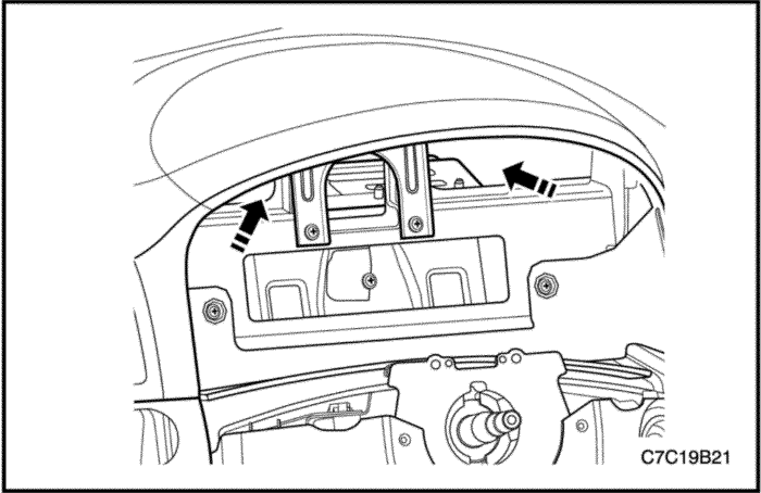


- You can see the X-BCM through the bracket hole and put your hands into the hole along the arrow.
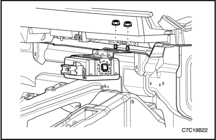


- Unlock the both side of X-BCM and remove two nuts through the hole.
- Pull out the bracket through the hole.
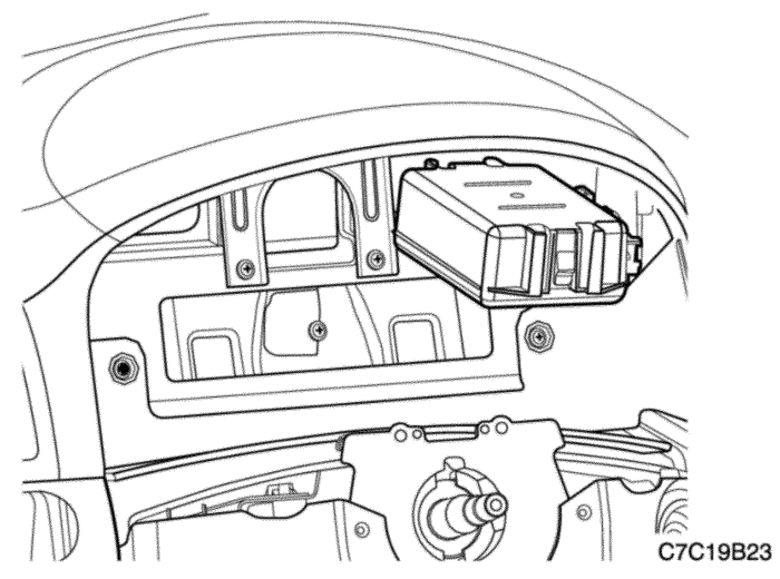


- Disconnect the electrical connector.
- Pull out the X-BCM through the hole.
Important : Perform the SPO reprogramming when X-BCM module replaced.


Installation Procedure
- Connect the electrical connector.
- Install the X-BCM and bracket with the nuts into the hole.


- Install the instrument cluster. Refer to Section 9E, Instrumentation/Driver Information.
- Connect the negative battery cable.
GENERAL DESCRIPTIONAND SYSTEM OPERATION
Headlamps
The headlamps are controlled by the multifunction lever on the left side of the steering column. They will come on with the ignition switch in ON position. If the headlamp switch is ON and the ignition key is in ACC or LOCK position, the headlamp will be turned off automatically. Turning the headlamp switch to the first position turns on the parking lamps, the license plate lamps, and the instrument panel illumination. Turning the switch to the second position turns on all of the previous lamps and the headlamps. Turning the switch OFF turns off all the lamps.
The headlamps may be turned on in 2 different ways. First, when the driver places the headlamp switch in the HEADLAMP position, for normal operation. Second, with the headlamp switch placed in the AUTO position, for automatic lamp control (ALC). During ALC the headlamps will be in DRL operation in daylight conditions, or headlamp operation in low light conditions.
Headlamp ON/OFF control is determined by the body control module (BCM) by a signal on the headlamp switch on input circuit when the headlamp switch is in the HEAD position. When the headlamp switch is in the AUTO position, the BCM determines headlamps ON/OFF by the voltage from the ambient light sensor.
The headlamps high beam and low beams are also controlled by this lever. When the headlamps are on, pushing the lever away from the driver until the switch clicks changes the lamp from low beam to high beam. An indicator lamp on the instrument cluster assembly will come on when the high-beam headlamps are on. To return the headlamps to low beams, pull the lever toward the driver. The headlamps must be aimed for proper illumination of the road. Headlamp aim should be checked whenever a new headlamp assembly is installed or when service or repairs to the front end may have disturbed the headlamp assembly or its mountings.
Daytime Running Lamps
The ambient light sensor is a light-sensitive transistor that varies its voltage signal to the body control module (BCM) in response to changes in the outside (ambient) light level. When the BCM receives this signal the BCM either turns ON the just the low beam headlamps at reduced intensity for the daytime running lamp (DRL) operation or turns ON the low beam headlamps and the exterior lamps for automatic lamp control (ALC). Any function or condition that turns ON the headlamps will cancel the DRL operation. Thirty seconds after you start the engine with the headlamp switch in the OFF position, the DRL will perform one of two actions:
- Illuminate the low beam headlamps at reduced intensity in daylight conditions.
- Illuminate the low beam headlamps and exterior park lamps for low light conditions.
The DRL operates when the ignition switch is in the RUN position, the parking brake is not set and the transmission is not in the PARK position When these conditions are met and the DRL ambient light sensor indicates daylight conditions the DRL will illuminate.
Parking and Turn Signal Lamps
The parking lamps can be turned on by turning the headlamp switch to the first position. The parking lamps can be turned off by turning the switch off.
When the turn signals are activated, the appropriate turn signal lamps flash to signal a turn. The front, the rear, and the side turn signals work only when the ignition is on.
The front and the rear turn signals are controlled by the multifunction lever on the left side of the steering column. Moving the lever all the way up or down past the detent will turn on the turn signals. When the turn is complete, the lever will automatically release, and the front and the rear turn signals will stop flashing.
For changing lanes or shallow turns in which the steering wheel does not turn far enough to cancel the signal, move the signal to the first detent and hold it there. The turn signal will cancel when the lever is released.
Fog Lamps
The fog lamp switch is on the instrument panel above the audio system. To use the fog lamps, first turn on the headlamps. Then, push the fog lamp switch. The indicator light in the instrument cluster will illuminate to indicate that the fog lamps are on. Push the switch again to turn off the fog lamps. The indicator light will then go off.
The fog lamps must be aimed for proper illumination of the road. Fog lamp aim should be checked when a new bulb is installed or if service or repairs to the front end may have disturbed the fog lamp assembly or its mountings.
Rear Combination Lamps
The taillamps, stoplamps, backup lamps, and turn signals are one assembly.
Turning on either the headlamps or the parking lamps will also turn on the taillamps. When the brake pedal is pushed, the taillamps will glow more brightly to serve as stoplamps.
Center High-Mounted Stoplamp
The center high-mounted stoplamp is in the rear window and will come on when the brake pedal is pressed.
Backup Lamps
The backup lamps will come on when the transaxle is shifted into reverse. On a vehicle with an automatic transaxle, the backup lamps are activated by the park/ neutral position switch.
License Plate Lamps
The license plate lamps will come on when the headlamps or the parking lamps are on. The license plate lamps are mounted on the rear deck lid, above the license plate.
Export Body Control Module (XBCM)
Important : Perform the SPO reprogramming when X - BCM module replaced. X - BCM module is located behind of the cluster.
- Alarm Siren Module Function
The XBCM shall be the master of communications with the vehicle Alarm Siren Module. The XBCM shall arm, disarm, and set alarm based on the current CTD or VTD theft state. The XBCM will receive commands from GMLAN signals that define the current CTD state of the vehicle.
- Auxiliary Content Theft Deterrent (CTD) Horn Function
The XBCM shall provide for control of the auxiliary CTD horn relay.
- Trailer Stop/Turn Outage Detection Function
Legal regulations require the turn signal feature to be capable of detecting when one or more of its lamps are not functioning. For this reason, the XBCM shall track the state of the Left and the Right side Trailer Stop/Turn lamps separately to determine if a Stop/Turn signal is malfunctioning.


