MAINTENANCE AND REPAIR
ON-VEHICLE SERVICE
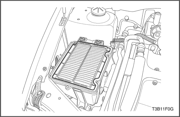


Air Filter
Removal & Installation Procedure
- Remove the air filter upper housing.
- Replace the air filter element.
Notice : Before replacing a new one, check the maintenance interval and the quality of the air cleaner element.
Tighten
Air Filter Upper Housing Bolts : 2 N•m (1.5 lb-ft).
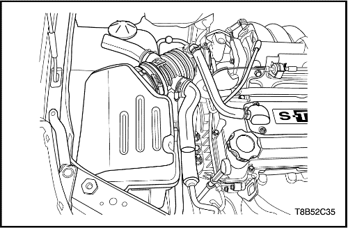
Air Cleaner Assembly
Removal Procedure
- Disconnect the negative battery cable.
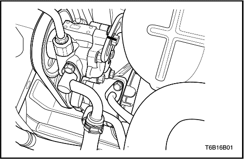
- Disconnect the breather hose.
- Loosen the clamp and disconnect outlet tube.
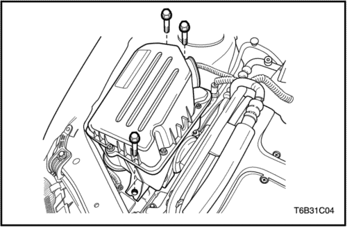
- Remove the air cleaner assembly bolts.
- Remove the air cleaner assembly.
Installation Procedure
- Install the air cleaner assembly.
- Install the air cleaner assembly bolts.
Tighten
Air Cleaner Assembly Bolts : 6 N•m (4.4 lb-ft).
- Connect the air cleaner outlet tube and tighten the clamp.
- Connect the breather hose.
- Connect the negative battery cable.
Accessory Belt and Tensioner
Removal Procedure
- Remove the air cleaner assembly.
- Lift the vehicle up.
- Remove the front-right tire and wheel.
- Remove the engine under-cover.
- Remove the power steering pump bracket retaining bolts and loosen the belt.
- Remove the power steering pump-air compressor belt.

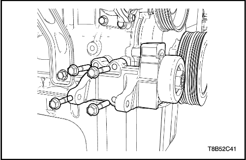
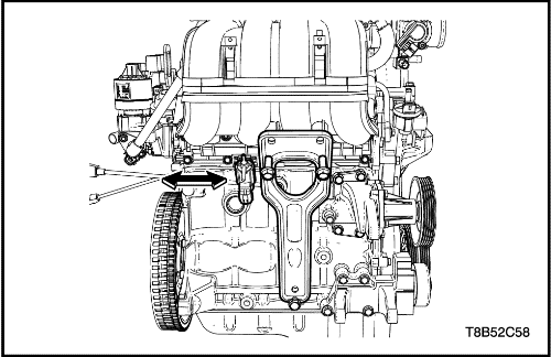
- Rotate the accessory tensioner hex-socket bolt (M8) counter clockwise and loosen it.
Caution : Not to rotate the accessory tensioner hex-socket bolt (M8) many times. If rotated many times, the backside nut of the tensioner may be dropped.
- Remove the water pump-generator belt.
Caution : When removing the belt, do not rotate the tensioner hex-nut (M24) first. First is the accessory tensioner hex-socket bolt (M8). If rotate the tensioner hex-nut (M24) first, tensioner and bracket tooth may be damaged.
- Remove the generator.
- Remove the accessory tensioner.
Installation Procedure
- Install the accessory tensioner.
Tighten
Accessory Tensioner - Generator Assembly Bracket Mounting Bolt : 25 N•m (18.4 lb-ft).
- Install the generator.
- Rotate the tensioner hex-nut (M24) counterclockwise and put up the tensioner with a suitable interchangeable head, click-type torque wrench
- New Belt : 24 N•m (18 lb-ft)
- Used Belt : 17.5 N•m (13 lb-ft)
- Rotate the tensioner hex-socket bolt (M8) clockwise and tighten the bolt, installing the water pump-generator belt.
Tighten
Accessory Tensioner Hex-Socket Bolt (M8): 45 N•m (33.2 lb-ft).
Notice : When rotating, check the tensioner and bracket tooth.
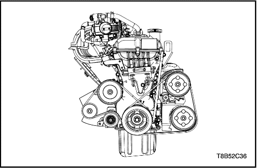
- Install the power steering pump-air compressor belt, tightening power steering pump bracket retaining bolts.
Tighten
Power Steering Pump Bracket Mounting Bolts: 25 N•m (18.4 lb-ft).
Intake Manifold
Removal Procedure
Caution : Do not remove when the engine is hot. It may cause damage and can be injured.
- Disconnect the negative battery cable.
- Remove the air cleaner assembly. Refer to “Air Cleaner Assembly”
in this section.
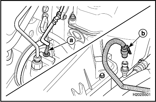
- Disconnect the power steering oil pressure switch connector and the air conditioner pressure sensor connector.
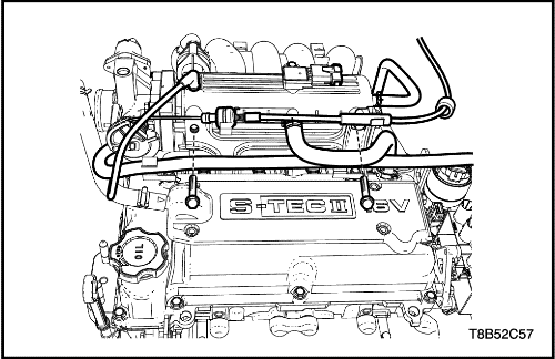
- Disconnect the brake vacuum hose.
- Disconnect the PCV breather hose.
- Disconnect the intake temperature/pressure sensor connector.
- Disconnect the accelerator cable.
- Disconnect the canister hose from the intake manifold.
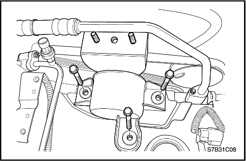
- Remove intake manifold front bracket upper retaining bolts.
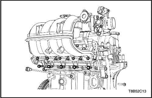
- Remove the fuel rail.
- Remove the EGR pipe.
- Disconnect the VGIS solenoid valve.
- Remove the intake manifold rear bracket bolts.
- Remove the intake manifold rear bracket.
- Remove the engine wiring harness from the intake manifold.
- Remove the intake manifold.
- Remove the intake manifold gasket.
Installation Procedure
- Install the intake manifold with the new gasket.
- Tighten the intake manifold bolts.
Tighten
Intake Manifold Retaining Bolts : 10 N•m (7.4 lb-ft).
- Install the intake manifold rear bracket.
- Install the intake manifold rear bracket retaining bolts.
Tighten
- Bracket Upper Bolts : 25 N•m (18.4 lb-ft).
- Bracket Lower Bolts: 50 N•m (36.8 lb-ft).
- Install the EGR pipe.
- Install the fuel rail. Refer to Section 1F1, Engine Controls.
- Tighten the intake manifold front bracket upper retaining bolts.
Tighten
Intake Manifold Support Bracket Upper Bolts : 2 N•m (1.5 lb-ft).
- Connect the brake vacuum hose.
- Connect the PCV breather hose.
- Connect the intake temperature/pressure sensor connector.
- Connect the accelerator cable.
- Connect the canister hose from the intake manifold.
- Connect the power steering oil pressure switch connector and the air conditioner pressure sensor connector.
- Install the air cleaner assembly. Refer to “Air Cleaner Assembly”
in this section.
- Connect the negative battery cable.
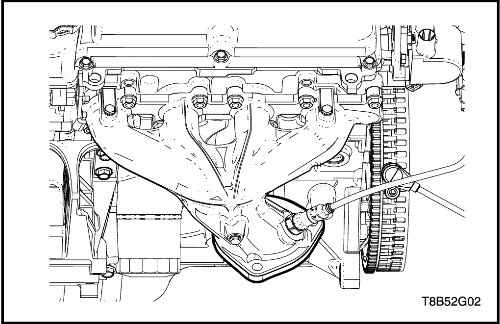
Exhaust Manifold
Caution : Do not remove when the exhaust manifold parts are hot.
Removal Procedure
- Remove the fuel pump fuse.
- Start the engine. After it stalls, crank the engine after it stalls for 10 seconds to rid the fuel system of fuel pressure.
- Disconnect the oxygen sensor connector.
- Remove the catalitic converter. Refer to Section 1G, Engine Exhaust.
- Remove the exhaust manifold.
Installation Procedure
- Tighten the exhaust manifold retaining bolts/nuts.
Tighten
- Exhaust Manifold Retaining Bolts : 25 N•m (18.4 lb-ft).
- Exhaust Manifold Retaining Nuts : 20 N•m (14.7 lb-ft).
- Install the catalitic converter. Refer to Section 1G, Engine Exhaust.
- Connect the heater outlet hose from the coolant pipe.
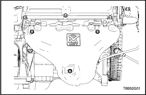
- Install the exhaust manifold heat shield.
Tighten
Exhaust Manifold Heat Shield Bolts : 15 N•m (11 lb-ft).
- Connect the negative battery cable.
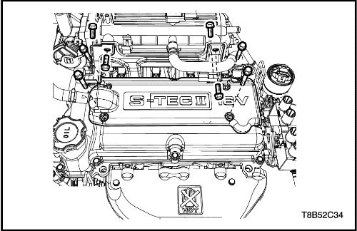
Cylinder Head Cover
Removal Procedure
- Disconnect the negative battery cable.
- Disconnect the PCV hose.
- Remove the cylinder Head cover bracket and bolts.
- Remove the spark plug cable cover.
- Disconnect the spark plug cable.
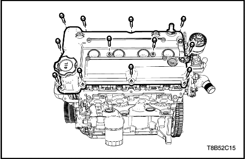
- Remove the cylinder head cover retaining bolts.
- Remove the cylinder Head cover with the gasket.
Installation Procedure
- Install the cylinder Head cover with the gasket.
- Tighten the cylinder head cover retaining bolts.
Tighten
Cylinder Head Cover Bolts : 10 N•m (7.4 lb-ft).
- Connect the ignition cable.
- Install the ignition cable cover.
- Tighten the cylinder head cover bracket retaining bolts.
Tighten
- Cylinder Head Cover Bracket Bolts : 10 N•m (7.4 lb-ft).
- Spark Plugs Cable Cover Bolts : 10 N•m (7.4 lb-ft).
- Connect the PCV hose.
- Connect the negative battery cable.
Timing Chain System
Tools Required
Removal Procedure
- Disconnect the negative battery cable.
- Remove the air cleaner assembly. Refer to “Air Cleaner Assembly”
in this section.
- Remove the cylinder head cover. Refer to “Cylinder Head Cover”
in this section.
- Remove the accessory belt and tensioner. Refer to “Accessory Belt”
in this section.
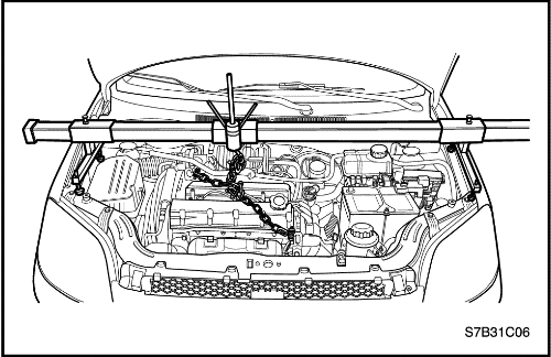
- Install the engine fixture(EN–48356).
- Remove the engine mount. Refer to “Engine Mount”
in this section.
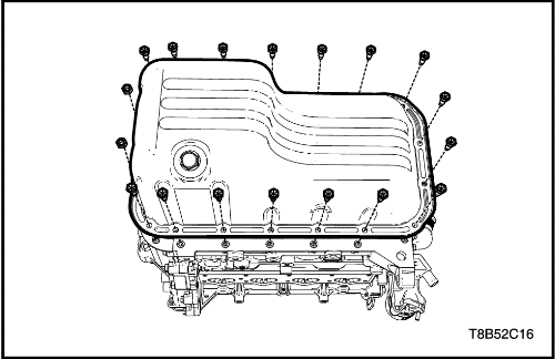
- Remove the oil pan. Refer to “Oil Pan”
in this section.
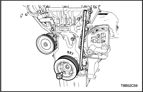
- Remove the crankshaft pulley.
- Remove the oil level gauge tube.
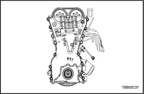
- Remove the timing chain cover.
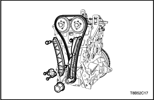
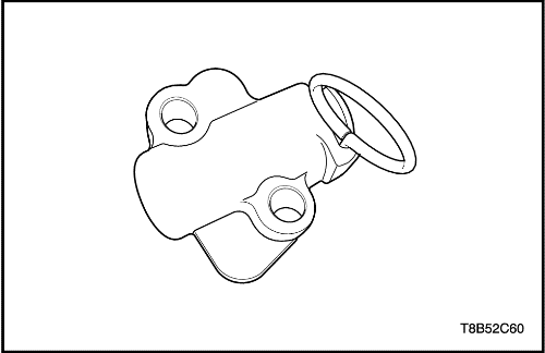
- Remove the timing chain tensioner.
- Remove the timing chain lever. (left side)
- Remove the timing chain guide. (right side)
- Remove the timing chain.
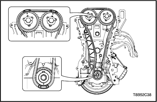
Valve Timing Adjustment
- Install the timing chain after aligning both the mark on the camshaft sprocket and on the timing chain.
- Align both the timing mark on the crankshaft sprocket and on the timing chain.
- Push the timing chain tensioner lever and fix the lever by installing the tensioner pin(EN-49073).
- Assemble the timing chain guide.
Tighten
Timing Chain Guide Retaining Bolts : 10 N•m (7.4 lb-ft).
- Assemble the timing chain lever.
Tighten
Timing Chain Lever Retaining Bolts : 10 N•m (7.4 lb-ft).
- Assemble the timing chain tensioner.
Tighten
Timing Chain Tensioner Retaining Bolts : 12 N•m (8.8 lb-ft).
Installation Procedure
- Install the timing chain cover.
Tighten
- Timing Chain Cover Retaining Bolts (M6 x 1.0) : 10.5 N•m (7.7 lb-ft).
- Timing Chain Cover Retaining Bolts (M8 x 1.25) : 20 N•m (14.7 lb-ft).
- Install the crankshaft pulley.
Tighten
Crankshaft Pulley Bolt : 85 N•m (62.7 lb-ft).
- Install the oil level gage tube.
Tighten
Oil Level Gage Tube Retaining Bolt : 10.5 N•m (7.7 lb-ft).
- Tighten the timing chain tensioner bolts.
Tighten
Timing Chain Tensioner Retaining Bolts : 12 N•m (8.8 lb-ft).
- Apply the liquid gasket on the timing chain cover.
- Install the oil pan. Refer to “Oil Pan”
in this section.
- Install the engine mount. Refer to “Engine Mount”
in this section.
- Install the accessory belt and tensioner. Refer to “Accessory Belt”
in this section.
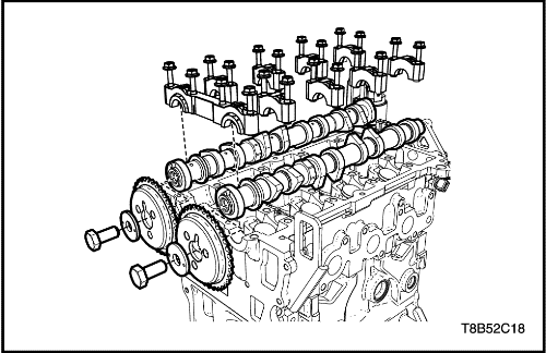
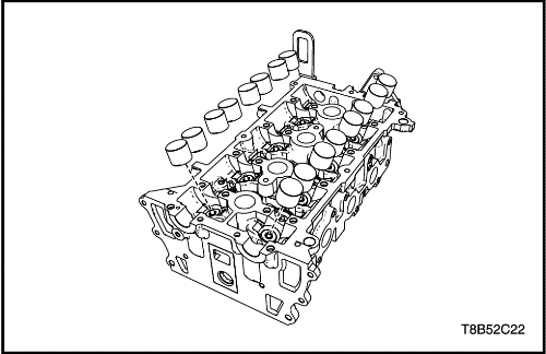
Camshafts
Removal Procedure
Caution : Make sure that camshaft caps have to be set on the original position and direction. If mixed, damage may happen to engine.
Notice : Take extreme care to prevent any scratches, nicks or damage to the camshafts.
- Remove the timimg chain. Refer to “Timing Chain System”
in this section.
- Remove the camshaft sprocket bolts.
- Remove the camshaft sprocket.
- Remove the camshaft caps.
- Remove the camshaft.
Installation Procedure
- Lubricate the camshaft journals and the camshaft caps with engine oil.
- Install the camshaft caps in their original positions.
Tighten
Camshaft Cap Bolts : 10 N•m (7.4 lb-ft).
- Install the camshaft sprocket.
Tighten
Camshaft Sprocket Retaining Bolts : 60 N•m (44.2 lb-ft).
- Install the timimg chain. Refer to “Timing Chain System”
in this section.
Valve Spring
Tools Required
EN-49074 Compressor-Universal Valve Spring
EN-49075 Adapter-Valve Spring Compressing
EN-49076 Adapter-Cylinder Pressure
Removal Procedure
- Remove the camshaft. Refer to “Camshaft”
in this section.
Caution : Do not scratch on the valve tappet. And must not use a gloves or tools.
- Remove the valve tappet.
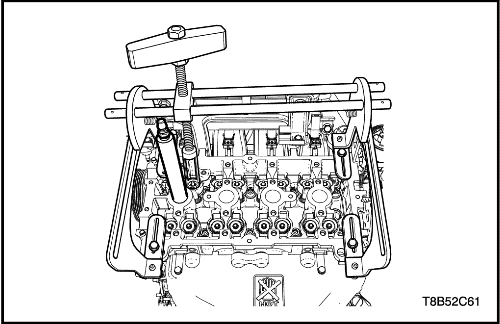
- Install the universal valve spring compressor(EN-49074) and adapter(EN-49075).
- Remove the spark plug and install the cylinder compression adapter(EN-49076).
- Install the compressed air hose to the cylinder compression adapter(EN-49076). It keeps the valve not slip into the cylinder by blowing compressed air into the cylinder.
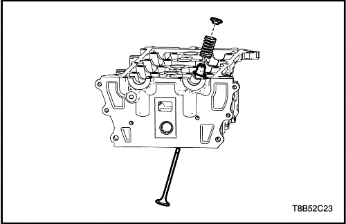
- Remove the valve spring, retainer, and seal.
Installation Procedure
- Install the universal valve spring compressor(EN-49074) and adapter(EN-49075).
- Remove the spark plug and install the cylinder compression adapter(EN-49076).
- Install the compressed air hose to the cylinder compression adapter(EN-49076). It keeps the valve not slip into the cylinder by blowing compressed air into the cylinder.
- Install the valve spring, retainer, and seal.
Caution : Do not scratch on the valve tappet. And must not use a gloves or tools.
- Install the valve tappet.
- Install the camshaft. Refer to “Camshaft"
in this section.
| © Copyright Chevrolet Europe. All rights reserved |


