SECTION 1G
ENGINE EXHAUST
SPECIFICATIONS
Fastener Tightening Specifications
|
Application
|
N•m
|
Lb-Ft
|
Lb-In
|
|
Catalytic Converter-to-Exhaust Manifold Nuts
|
40
|
30
|
-
|
|
Exhaust Front Pipe-to-Catalytic Converter Nuts
|
40
|
30
|
-
|
|
Exhaust Manifold Heat Shield Bolts (B12D)
|
15
|
11
|
-
|
|
Exhaust Manifold Heat Shield Bolts (G14D)
|
8
|
5.9
|
-
|
|
Front Muffler-to-Exhaust Front Pipe Nuts
|
40
|
30
|
-
|
|
Front Muffler-to-Rear Muffler Nuts
|
40
|
30
|
-
|
|
Heated Oxygen Sensor
|
40
|
30
|
-
|
COMPONENT LOCATOR
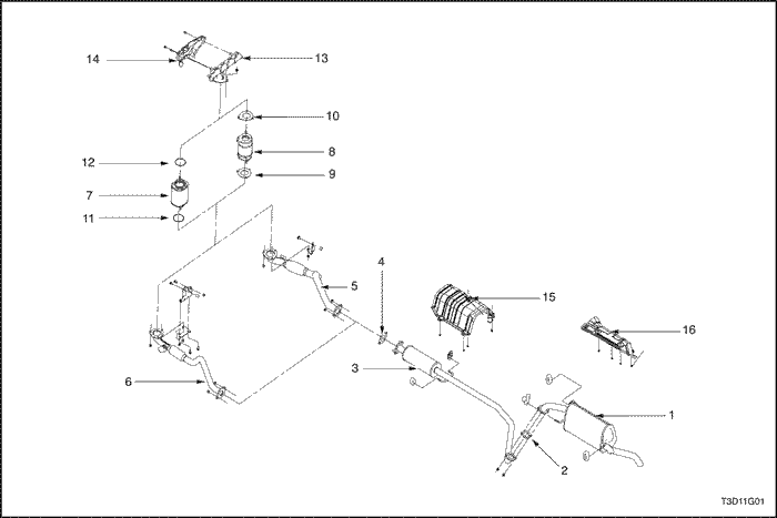
Exhaust System
- Exhaust Rear Muffler
- Muffler Gasket
- Exhaust Front Muffler
- Muffler Gasket
- Exhaust Front Pipe (1.4D)
- Exhaust Front Pipe (1.2D)
- Pop Converter
- Exhaust Front Resonator
- Exhaust Pipe Front Gasket
- Exhaust Front Pipe Gasket
- Pop Converter Gasket
- Pop Converter Gasket
- Exhaust Manifold
- Exhaust Manifold Shield
- Underbody Protective Shield
- Underbody Protective Shield
MAINTENANCE AND REPAIR
ON-VEHICLE SERVICE


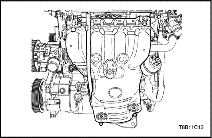
Catalytic Converter - 1.2 DOHC - B12D -
Removal Procedure
- Disconnect the negative battery cable.
- Disconnect the front heated oxygen sensor connector.
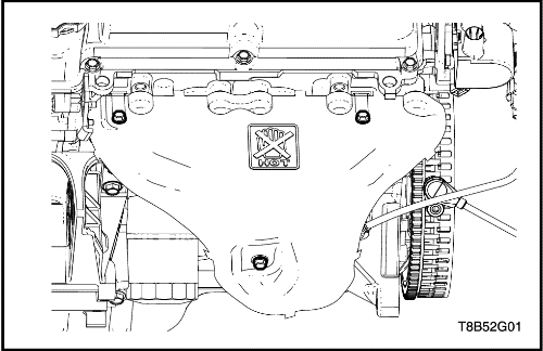
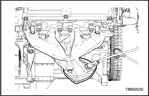
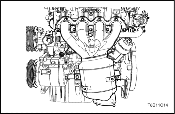
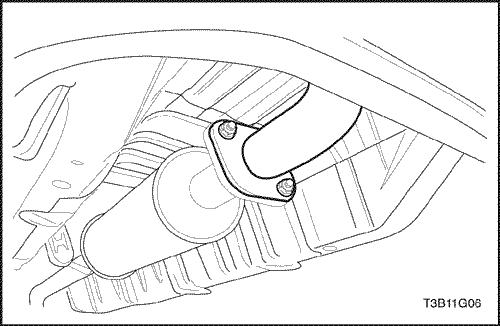
- Remove the exhaust manifold heat shield.
- Remove the catalytic converter upper flange nuts.
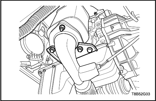
- Remove the exhaust front pipe mounting bracket bolt.
- Remove the catalytic converter lower flange nuts.
- Remove the catalytic converter and the gasket.
Installation Procedure
- Install the catalytic converter and the gasket.
Important : Position the catalytic converter
onto the exhaust manifold flange with one upper flange
nut .
- Install the catalytic converter lower flange nuts and the exhaust front pipe mounting bracket.
Tighten
- Tighten the exhaust front pipe to catalytic converter nuts to 40 N•m (30 lb-ft).
- Tighten the exhaust front pipe mounting bracket bolt to 40 N•m (30 lb-ft).
- Install the catalytic converter upper flange nuts.
Tighten
Tighten the catalytic converter to exhaust manifold nuts to
40 N•m (30 lb-ft).
- Install the exhaust manifold heat shield.
Tighten
Tighten the exhaust manifold heat shield bolts to
15N•m (11 lb-ft).
- Connect the front heated oxygen sensor connector.
- Connect the negative battery cable.
Catalytic Converter - 1.4 DOHC - G14D -
Removal Procedure
- Disconnect the negative battery cable.
- Disconnect the front heated oxygen sensor connector.
- Remove the oil level gage tube.
- Remove the exhaust manifold heat shield.
- Remove the catalytic converter upper flange nuts.
- Remove the exhaust front pipe mounting bracket bolt.
- Remove the catalytic converter lower flange nuts.
- Remove the catalytic converter and the gasket.
Installation Procedure
- Install the catalytic converter and the gasket.
Important : Position the catalytic converter
onto the exhaust manifold flange with one upper flange
nut .
- Install the catalytic converter lower flange nuts and the exhaust front pipe mounting bracket.
Tighten
- Tighten the exhaust front pipe to catalytic converter nuts to 40 N•m (30 lb-ft).
- Tighten the exhaust front pipe mounting bracket bolt to 40 N•m (30 lb-ft).
- Install the catalytic converter upper flange nuts.
Tighten
Tighten the catalytic converter to exhaust manifold nuts to
40 N•m (30 lb-ft).
- Install the exhaust manifold heat shield.
Tighten
Tighten the exhaust manifold heat shield bolts to 8 N•m (5.9 lb-ft).
- Install the oil level gage tube.
Caution : Check the oil. If the oil dropped when removing the oil level gage tube, check and refill it.
- Connect the front heated oxygen sensor connector.
- Connect the negative battery cable.
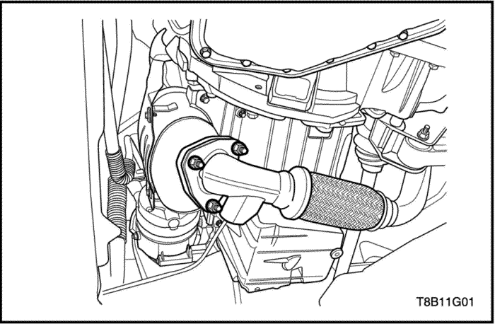
Exhaust Front Pipe
Removal Procedure
- Disconnect the negative battery cable.
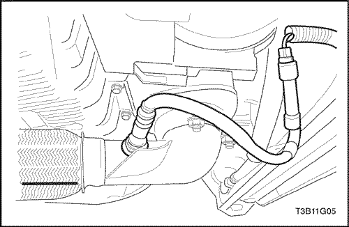
- Disconnect the rear heated oxygen sensor connector.
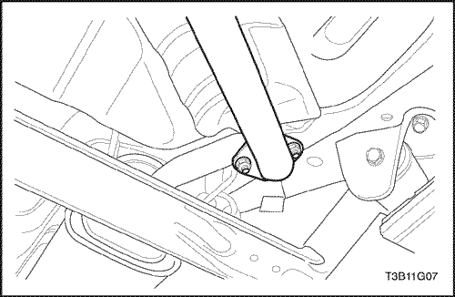
- Remove the exhaust front pipe mounting bracket bolt.
- Remove the catalytic converter lower flange nuts.
- Remove the nuts from the front muttler pipe to the exhaust front pipe.
- Remove the exhaust front pipe from the rubber hanger.
- Clean the sealing surtaces on the front muttler pipe flange and the exhaust front pipe.
- Check the exhaust front pipe for holes, damage, open seams, or other deterioration which could permit exhaust fumes to seep into the passenger compartment.
Installation Procedure
- Secure the exhaust front pipe to the rubber hanger.
- Install the nuts and gasket to the exhaust front pipe-to-front muffler.
Tighten
Tighten the front muffler to exhaust front pipe nuts to 40 N•m (30 lb-ft).
- Install the catalytic converter lower flange nuts and the exhaust front pipe mounting bracket.
Tighten
-
- Tighten the exhaust front pipe to catalytic converter nuts to 40 N•m (30 lb-ft).
- Tighten the exhaust front pipe mounting bracket bolt to 40 N•m (30 lb-ft).
- Connect the rear heated oxygen sensor connector.
- Connect the negative battery cable.
Muffler - Front
Removal Procedure
- Remove the nuts and the gasket from the front muffler pipe to the exhaust front pipe flange.
- Remove the nuts and the gasket from the rear muffler
pipe flange.
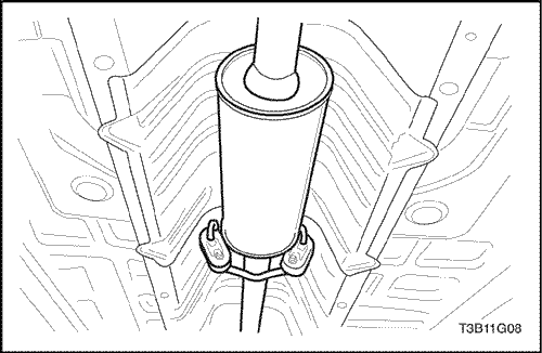
- Disconnect the front muffler from
the rubber hanger.
- Remove the front muffler.
- Check the exhaust pipe and the front muffler for
holes, damage, open seams, or other deterioration
which could permit exhaust fumes to seep into the
passenger compartment or the trunk.
Installation Procedure
- Connect the front muffler to the rubber hanger.
- Attach the front muffler and the gasket to the rear
muffler using the nuts. Secure the front muffler to the
rubber hanger.
Tighten
Tighten the front muffler-to-rear muffler nuts to 40 N•m (30 lb-ft).
- Loosely secure the front muffler assembly to the connecting pipe flange.
- Secure the front muffler assembly to the connecting pipe flange with the nuts.
Tighten
Tighten the front muffler-to-exhaust front pipe nuts to 40 N•m (30 lb-ft).
Muffler - Rear
Removal Procedure
- Remove the nuts and the gasket from the rear muffler
pipe flange-to-front muffler pipe flange.
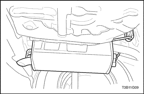
- Detach the rear muffler assembly from the rubber
hangers on the tail pipe end.
- Remove the rear muffler assembly.
- Check the rear muffler and the pipe for
holes, damage, open seams, and other deterioration
which could permit exhaust fumes to seep into the
passenger compartment or the trunk.
Installation Procedure
- Secure the rear muffler assembly to the rubber hangers on the tail pipe end.
- Secure the nuts and the gasket from the rear muffler
pipe flange-to-front muffler pipe flange.
Tighten
Tighten the front muffler-to-rear muffler nuts to 40 N•m (30 lb-ft).
GENERAL DESCRIPTION AND SYSTEM OPERATION
Exhaust System
Notice : When you are inspecting or replacing the exhaust
system components, make sure there is adequate
clearance from all points on the underbody to avoid possible
overheating of the floor pan and possible damage
to the passenger compartment insulation and trim materials.
Caution :
Check the complete exhaust system and
the nearby body areas and the trunk lid for broken,
damaged, missing, or mispositioned parts, open
seams, holes, loose connections, or other deterioration
which could permit hazardous exhaust
fumes to seep into the trunk or the passenger
compartment. Dust or water in the trunk may be an
indication of a problem in one of these areas. Any
defects should be corrected immediately.
Muffler
If holes, open seams or any deterioration is discovered
upon inspection of the front muffler and pipe assembly,
the complete assembly should be replaced. The
same procedure is applicable to the rear muffler assembly.
Heat shields in the front and the rear muffler assembly
positions, as well as for the catalytic converter and
the connecting pipe, protect the vehicle and the environment
from high temperatures the exhaust system develops.
Catalytic Converters
Notice : The catalytic converter requires the use of unleaded
fuel only, or damage to the catalyst will result.
The catalytic converters are emission control devices
added to the exhaust system to reduce pollutants from
the exhaust pipes.
The three-way catalyst has coatings
which contain palladium, platinum and rhodium, which simultaneouly lower the levels of HC, CO and NOx.