Aveo |
||||||||
|
||||||||
|
.
|
Parts Number
|
ID Number
|
Values(a)
|
|
1
|
24465260
|
04
|
3.060 - 3.050
|
|
2
|
24465261
|
06
|
3.050 - 3.070
|
|
3
|
24438041
|
08
|
3.070 - 3.090
|
|
4
|
24438145
|
10
|
3.090 - 3.110
|
|
5
|
24438146
|
12
|
3.110 - 3.130
|
|
6
|
24438147
|
14
|
3.130 - 3.150
|
|
7
|
24438148
|
16
|
3.150 - 3.170
|
|
8
|
24438149
|
18
|
3.170 - 3.190
|
|
9
|
24438150
|
20
|
3.190 - 3.210
|
|
10
|
24438151
|
22
|
3.210 - 3.230
|
|
11
|
55353764
|
24X
|
3.230 - 3.244
|
|
12
|
55353765
|
25X
|
3.244 - 3.258
|
|
13
|
55353766
|
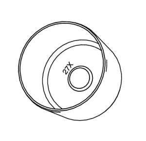
27X
|
3.258 - 3.272
|
|
14
|
55353767
|
28X
|
3.272 - 3.286
|
|
15
|
55353768
|
30X
|
3.286 - 3.300
|
|
16
|
55353769
|
31X
|
3.300 - 3.314
|
|
17
|
55353770
|
32X
|
3.314 - 3.328
|
|
18
|
55353771
|
34X
|
3.328 - 3.342
|
|
19
|
55353772
|
35X
|
3.342 - 3.356
|
|
20
|
55353773
|
36X
|
3.356 - 3.370
|
|
21
|
55353774
|
38X
|
3.370 - 3.384
|
|
22
|
55353775
|
39X
|
3.384 - 3.398
|
|
23
|
55353776
|
41X
|
3.398 - 3.412
|
|
24
|
55353777
|
42X
|
3.412 - 3.426
|
|
25
|
55353778
|
43X
|
3.426 - 3.440
|
|
26
|
55353779
|
45
|
3.440 - 3.460
|
|
27
|
55353780
|
47
|
3.460 - 3.480
|
|
28
|
55353781
|
49
|
3.480 - 3.500
|
|
29
|
55353782
|
51
|
3.500 - 3.520
|
|
30
|
55353783
|
53
|
3.520 - 3.540
|
|
.
|
Parts Number
|
ID Number
|
Values(a)
|
|
31
|
55353784
|
55
|
3.540 - 3.560
|
|
32
|
55353785
|
57
|
3.560 - 3.580
|
|
33
|
55353786
|
59
|
3.580 - 3.600
|
| © Copyright Chevrolet Europe. All rights reserved |


