

Flywheel - M/T Only -
Tools Required
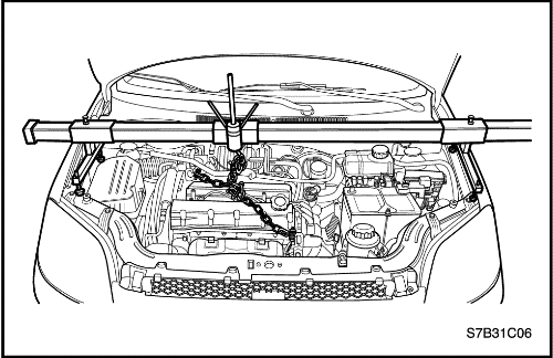
Engine Fixture EN–48356
Flywheel Locking Device KM-652
Removal Procedure
- Install the engine fixture EN-48356.
- Remove the manual transmission. Refer to Section 5B, Manual Transaxle.
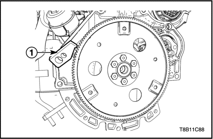
- Install the flywheel locking device(KM-652) to block the crankshaft.
- Install the transmission tightening bolt with KM-652.
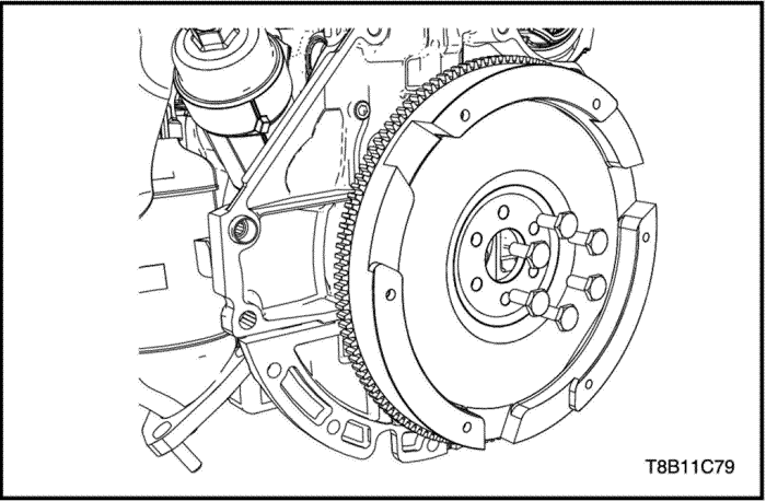
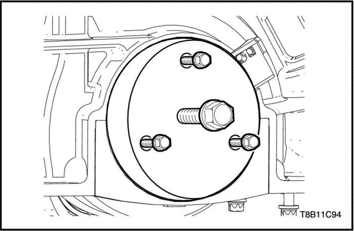
- Remove the flywheel bolts.
- Remove the flywheel.
Installation Procedure
- Remove the flywheel.
- Remove the flywheel bolts.
Tighten
Tighten the flywheel bolts to 35+30°+15° N•m (25.8+30°+15° lb-ft).
- Remove the flywheel locking device(KM-652) to block the crankshaft.
Flexible Plate - A/T Only -
Tools Required
Engine Fixture EN–48356
Flywheel Locking Device KM-652
Removal Procedure
- Install the engine fixture EN-48356.
- Remove the auto transmission. Refer to Section 5A, Automatic Transaxle.
- Install the flywheel locking device(KM-652) to block the crankshaft.
- Install the transmission tightening bolt with KM-652.
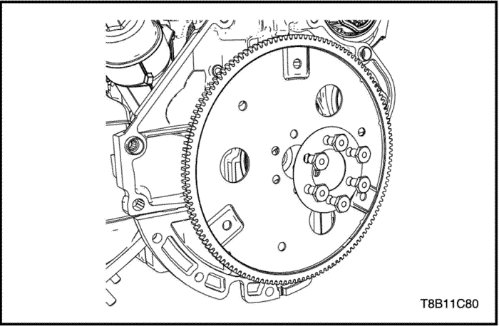
- Remove the flexible plate bolts.
- Remove the flexible plate.
Installation Procedure
- Remove the flexible plate.
- Remove the flexible plate bolts.
Tighten
Tighten the flexible plate bolts to 35+30°+15° N•m (25.8+30°+15° lb-ft).
- Remove the flywheel locking device(KM-652) to block the crankshaft.
Crankshaft Front Oil Seal Ring
Tools Required
Removal Procedure
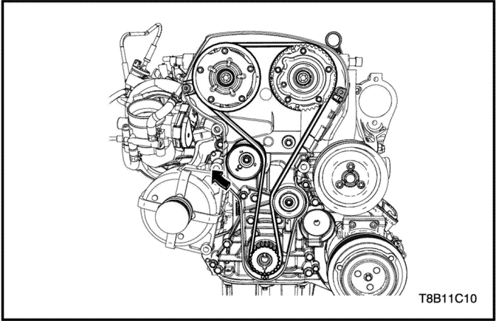
- Remove the timing belt. Refer to “Timing System”
in this section.
- Remove the crankshaft sprocket.
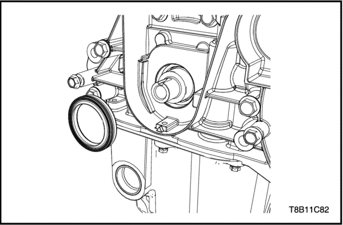
- Remove the crankshaft front oil seal ring.
Installation Procedure
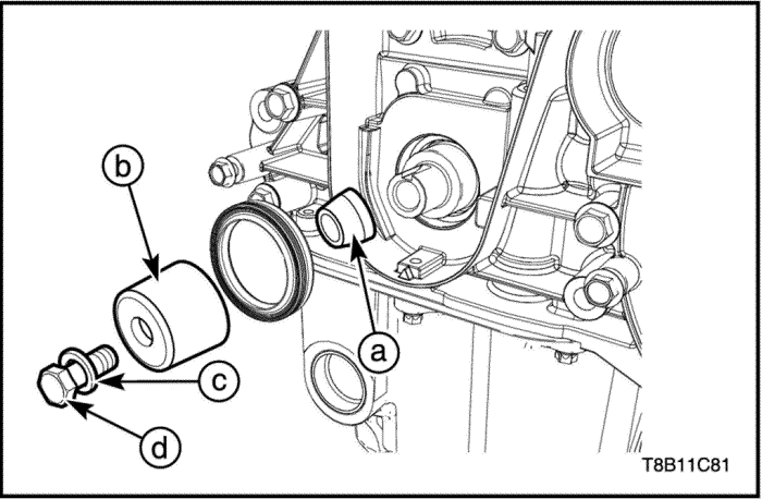
- Attach the installer inside sleeve(a).
- Attach the crankshaft front oil seal ring to the inside sleeve(a).
- Attach the installer outside sleeve(b).
- Install the crankshaft bolt(d) and washer(c).
- Install the crankshaft sprocket.
- Install the timing belt. Refer to “Timing System”
in this section.
Crankshaft Rear Oil Seal Ring
Tools Required
Crankshaft Rear Oil Seal Installer(-) EN-49204
Removal Procedure
- Remove the flywheel or flexible plate. Refer to “Flywheel (M/T ONLY)”
or “Flexible Plate (A/T ONLY)”
in this section.
- Remove the crankshaft position(CKP) sensor. Refer to Section 1F2, Engine Controls - 1.4 DOHC - G14D.
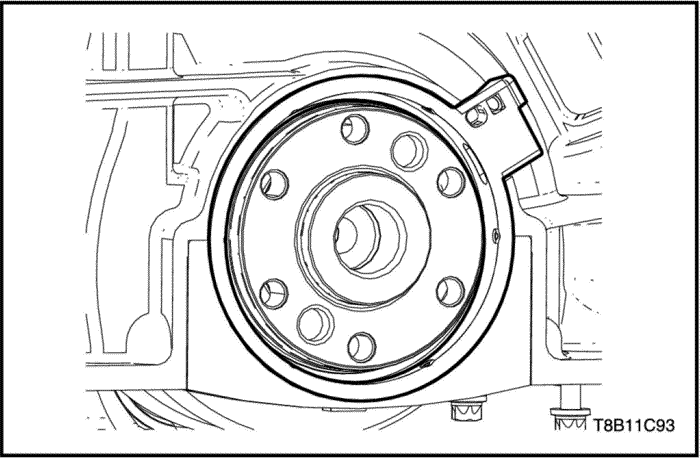
- Remove the crankshaft rear oil seal with housing.
Installation Procedure
- Install the new crankshaft rear oil seal.
- Install the installer EN-49204 and then tighten the bolts to press seal ring all the way in.
- Remove the installer EN-49204.
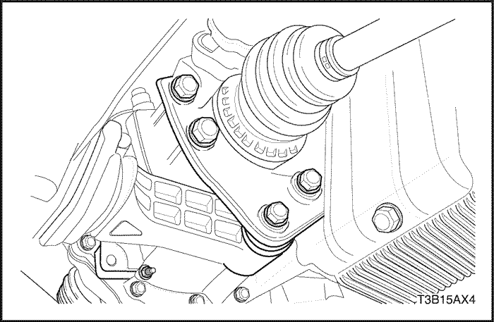
Engine Mount
Tools Required
Removal Procedure
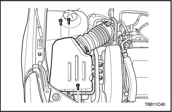
- Remove the air cleaner assembly. Refer to “Air Cleaner Assembly"
in this section.
- Install the engine fixture EN-48356.
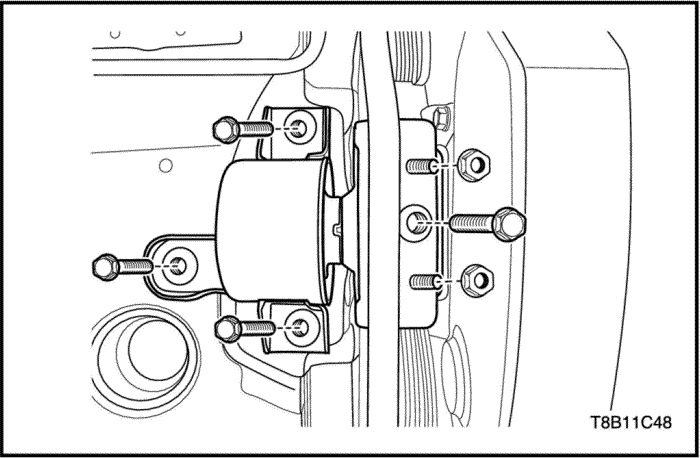
- Remove the engine mount bolts and nuts.
Installation Procedure
- Install the engine mount bolts and nuts.
Tighten
Tighten the engine mount bolts and nuts to 55 N•m (40.5 lb-ft).
- Remove the engine fixture EN-48356.
- Install the air cleaner assembly. Refer to “Air Cleaner Assembly"
in this section.
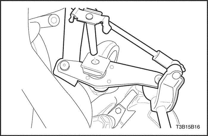
Reaction Rod
Remove and Installation Procedure
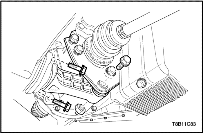
- Remove the reaction rod-to-bracket bolt and nut.
Tighten
Tighten reaction rod-to-bracket bolt and nut to 80 N•m (59 lb-ft).
- Remove the reaction rod-to-crossmember bolts.
Tighten
Tighten reaction rod-to-crossmember bolts to 55 N•m (40.5 lb-ft).
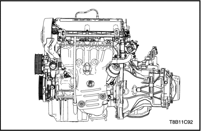
Engine Assembly
Tools Required
Engine Assembly Remove/Install Pallet Supporter EN-48244
Engine Assembly Remove/Install Pallet EN-49156
Removal Procedure
Caution : Do not accomplish this procedure when the engine is hot. It may cause damage and can be injured.
- Release the fuel pressure. Refer to Section 1F2, Engine Controls - 1.4 DOHC - G14D.
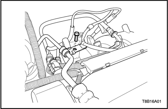
- Disconnect the fuel pipe from the fuel rail.
- Disconnect the EVAP hose from the EVAP canister solenoid valve.
- Drain the engine coolant. Refer to Section 1D, Engine Cooling.
- Remove the air cleaner assembly. Refer to “Air Cleaner Assembly"
in this section.
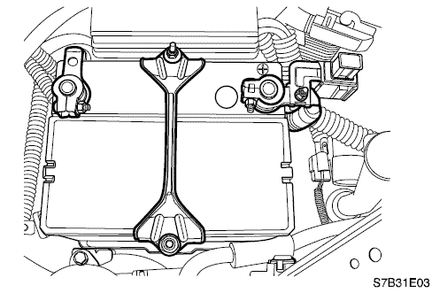
- Remove the battery and tray. Refer to Section 1E, Engine Electrical.
- Remove the fuse box tightening bolts.
- Discharge the A/C gas system, if equipped. Refer to Section 7B, HVAC System.
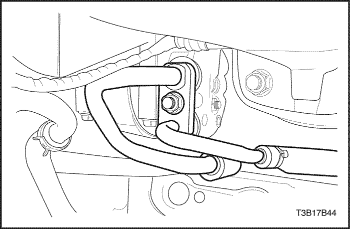
- Remove the A/C inlet/outlet pipe tightening bolt from the A/C compressor.
- Drain the power steering oil if equipped. Refer to Section 6A, Power Steering Pump.
- Remove the power steering pump pressure line union nut. Refer to Section 6A, Power Steering Pump.
- Remove the power steering pressure pipe retaining clamp bolt from the intake manifold. Refer to Section 6A, Power Steering Pump.
- Disconnect the power steering hose from the power steering pump. Refer to Section 6A, Power Steering Pump.
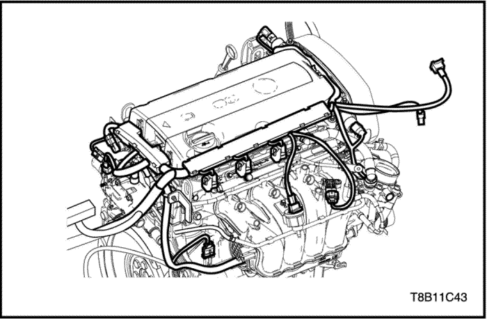
- Disconnect the related sensor and actuator connectors and the pull engine wiring harness aside.
- Oil Switch Wiring Connector
- A/C Compressor Connector
- Intake Air Temperature Sensor Connector
- A/C Pressure Sensor(ACP) Connector
- Cam Position Solenoid Valve Connector
- Electric Throttle Controller(ETC) Connector
- Manifold Air Pressure(MAP) Sensor Connector
- EVAP Solenoid Valve Connector
- Injector Connectors
- Ignition Coil Connector
- Camshaft Position Sensor(CPS) Connectors(Right/Left)
- Coolant Temperature Sensor Connector
- Oxygen Sensor Connector
- Ground Tightening Bolt
- Thermostat Heater Connector
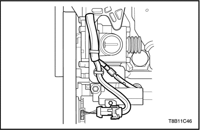
- Crankshaft Position(CKP) Sensor Connector
- Knock Sensor Connector
- Alternator Connector
- Alternator B+ Tightening Nut
- Oil Level Switch Connector(If equipped)
- Starter Solenoid B+ Tightening Nut
- Ground Tightening Nut
- Starter Solenoid Ground Tightening Nut
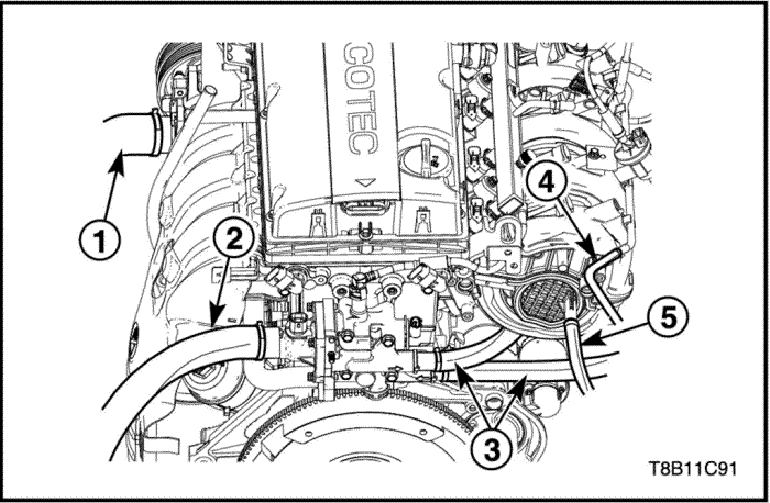
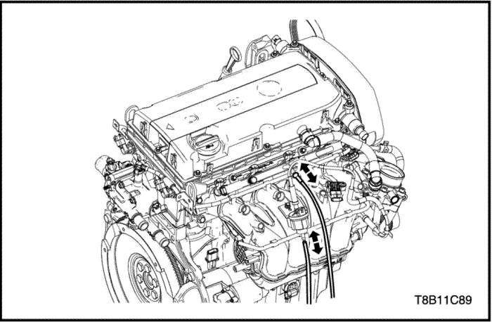
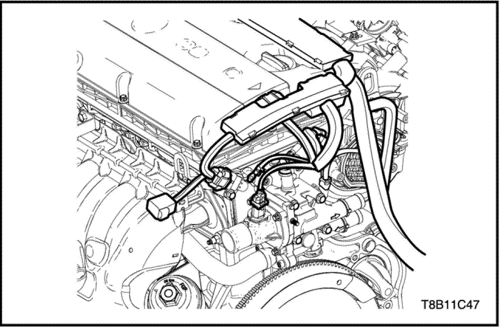
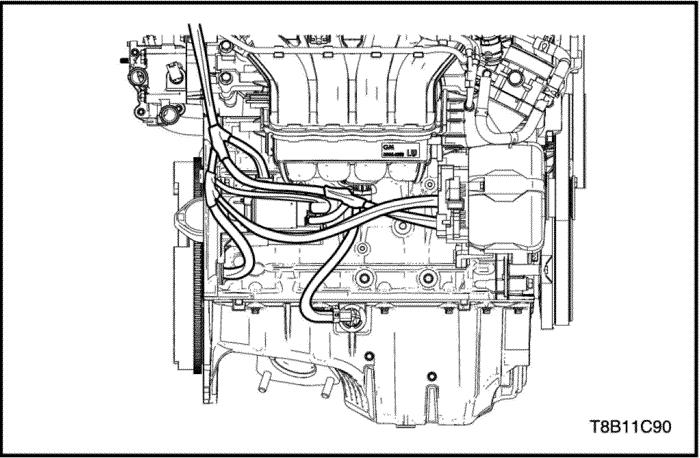
- Disconnect the coolant hose(1) from water pump.
- Disconnect the coolant hose(2) from the thermostat housing.
- Disconnect the heater core coolant inlet/outlet hoses(3) from the coolant distributor.
- Disconnect the ETC-to-coolant tank hose(4).
- Disconnect the brake boost hose(5) from the intake manifold.
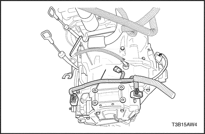
- Remove and disconnect the cables and wiring harness related to the automatic transaxle. Refer to Section 5A, AISIN Automatic Transaxle(A/T ONLY).
- Disconnect the auto transaxle fluid cooler inlet/outlet hoses. Refer to Section 5A, AISIN Automatic Transaxle(A/T ONLY).
- Remove and disconnect the cables and wiring harness related to the manual transaxle. Refer to Section 5B1, Five-Speed Manual Transaxle(D16)(M/T ONLY).
- Remove the reaction rod. Refer to “Reaction Rod”
in this section.
- Remove the exhaust front pipe. Refer to Section 1G, Engine Exhaust.
- Remove the drive axle shafts. Refer to Section 3A, Drive Axle.
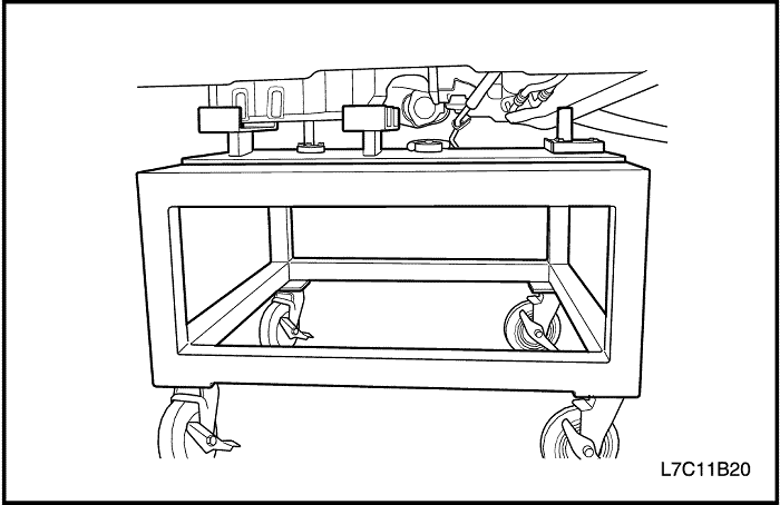
- Install the pallet EN-49156 on the supporter EN-48244.
- Lift the vehicle up using by lifter.
- Locate the pallet and supporter under the vehicle engine and transaxle.
- Lift the vehicle down until engine assembly fixing on the pallet EN-49156.
- Remove the engine mount. Refer to “Engine Mount”
in this section.
- Remove the transaxle mount. Refer to Section 5A, AISIN Automatic Transaxle(A/T ONLY).
Refer to Section 5B, Five-Speed Manual Transaxle(D16)(M/T ONLY).
- Separate the engine and the transaxle. Refer to Section 5A, AISIN Automatic Transaxle(A/T ONLY).
Refer to Section 5B, Five-Speed Manual Transaxle(D16)(M/T ONLY).
Installation Procedure
- Assemble the engine and the transaxle. Refer to Section 5A, AISIN Automatic Transaxle(A/T ONLY).
Refer to Section 5B, Five-Speed Manual Transaxle(D16)(M/T ONLY).
- Place the engine assembly on the pallet EN-49156 on the supporter EN-48244.
- Lift the vehicle up using by lifter.
- Locate the engine assembly with the pallet and supporter.
- Lift the vehicle down.
- Install the engine mount. Refer to “Engine Mount”
in this section.
- Install the transaxle mount. Refer to Section 5A, AISIN Automatic Transaxle(A/T ONLY).
Refer to Section 5B, Five-Speed Manual Transaxle(D16)(M/T ONLY).
- Install the drive axle shafts. Refer to Section 3A, Drive Axle.
- Install the exhaust front pipe. Refer to Section Section 1G, Engine Exhaust.
- Install the reaction rod. Refer to “Reaction Rod”
in this section.
- Install and connect the cables and wiring harness related to the automatic transaxle. Refer to Section 5A, AISIN Automatic Transaxle(A/T ONLY).
- Connect the auto transaxle fluid cooler inlet/outlet hoses. Refer to Section 5A, AISIN Automatic Transaxle(A/T ONLY).
- Install and connect the cables and wiring harness related to the manual transaxle. Refer to Section 5B1, Five-Speed Manual Transaxle(D16)(M/T ONLY).
- Connect the coolant hose(1) to the water pump.
- Connect the coolant hose(2) to the thermostat housing.
- Connect the heater core coolant inlet/outlet hoses(3) to the coolant distributor.
- Connect the ETC-to-coolant tank hose(4).
- Connect the brake boost hose(5) to the intake manifold.
- Connect the related sensor and actuator connectors.
- Crankshaft Position(CKP) Sensor Connector
- Knock Sensor Connector
- Alternator Connector
- Alternator B+ Tightening Nut
- Oil Level Switch Connector(If equipped)
- Starter Solenoid B+ Tightening Nut
- Ground Tightening Nut
- Starter Solenoid Ground Tightening Nut
Tighten
- Tighten the alternator B+ tightening nut to 15 N•m (11 lb-ft).
- Tighten the starter solenoid B+ tightening nut to 10.5 N•m (7.7 lb-ft).
- Tighten the ground tightening nut to 12 N•m (8.8 lb-ft).
- Tighten the starter solenoid ground tightening nut to 38 N•m (28 lb-ft).
- Ignition Coil Connector
- Camshaft Position Sensor(CPS) Connectors(Right/Left)
- Coolant Temperature Sensor Connector
- Oxygen Sensor Connector
- Ground Tightening Bolt
Tighten
Tighten the ground tightening bolt to 12 N•m (8.8 lb-ft).
- Thermostat Heater Connector
- Oil Switch Wiring Connector
- A/C Compressor Connector
- Install the power steering pump pressure line union nut. Refer to Section 6A, Power Steering Pump.
- Install the power steering pressure pipe retaining clamp bolt to the intake manifold. Refer to Section 6A, Power Steering Pump.
- Connect the power steering hose to the power steering pump. Refer to Section 6A, Power Steering Pump.
- Install the A/C inlet/outlet pipe tightening bolt from the A/C compressor if equipped.
- Charge the A/C gas system. Refer to Section 7B, HVAC System.
- Install the fuse box tightening bolts.
- Install the battery and tray. Refer to Section 1E, Engine Electrical.
- Install the air cleaner assembly. Refer to “Air Cleaner Assembly"
in this section.
- Connect the fuel pipe to the fuel rail.
- Connect the EVAP hose to the EVAP canister solenoid valve.
 |
|
 |
|
| © Copyright Chevrolet Europe. All rights reserved |


