GENERAL DESCRIPTION AND SYSTEM OPERATION
Intake and Exhaust Manifold
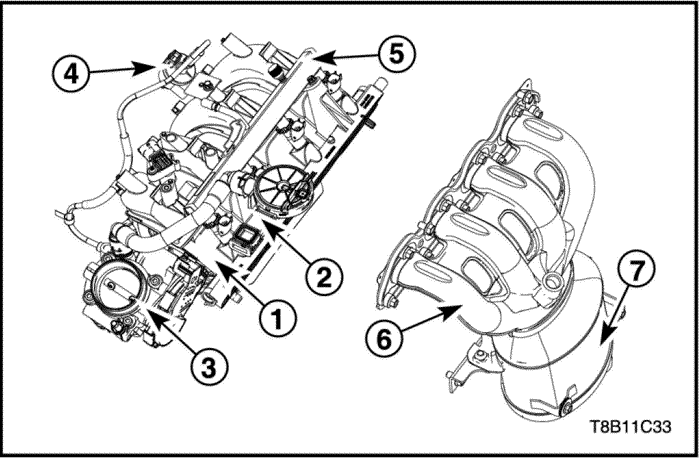


The intake manifold is air flow passage to the cylinder combustion chamber through the throttle body and has an effect on engine torque, power, noise, drivability, emission, fuel economy and performance. It is made of poly amid for weight reduction.
The exhaust manifold with C.C Catalytic Converter is located to the cylinder head and sent the front exhaust pipe the exhaust gas out of the combustion chamber. It is designed to endure on high pressure and high temperature and made of Stainless steel material.
- Intake Manifold
- PCV valve
- Throttle Body
- EVAP Solenoid Valve
- Fuel Rail
- Exhaust Manifold
- Catalytic Converter
Valve Train
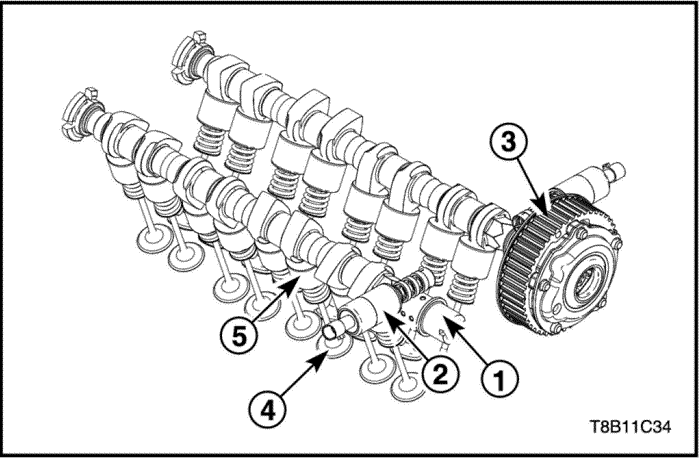
This valve train system is applied on direct acting type. By cranktrain rotation, intake/exhaust camshaft can be drove and this operation occur the each opening/closing of 2 intake valve/2 exhaust valve. This total operation brings out the combustion of cylinder space. VCP is applied for variable cam timing.
Due to systemical characteristics (Direct acting type), tappet can be directly contacted with the cam-profile of camshaft and the each different gap between intake valve and exhaust valve with tappet must be maintained. And this valve train system is composed of valve spring, valve stem seal, valve spring retainer and valve key.
- Camshaft
- VCP(Variable Camshaft Position) Solenoid Valve
- Camshaft Sprocket
- Valve
- Tappet
Cylinder Head
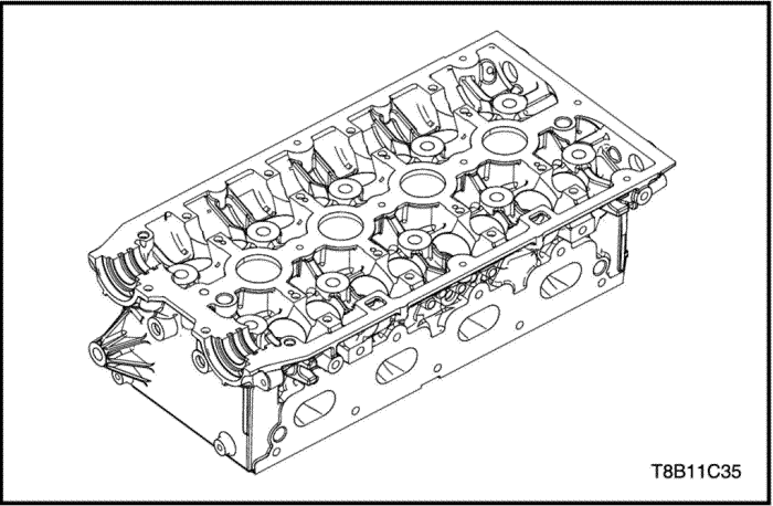
This cylinder head apply on DOHC(Double Over Head Camshaft) type, which have two camshafts rotating by combustion force and make combustion in the combustion chamber with operating(open&close) 4 valves by camshaft rotating. The bottom part of Cylinder head could get the cover shape (which is called as combustion chamber) with Cylinder Block and Piston. Therefore, The material of Cylinder head, which make combustion chamber, is applied on Aluminum alloy that have the good characteristics of cooling effect and stiffness for protecting it from high temperature and combustion pressure.
As the internal part, Cylinder head have water jacket for giving the coolant flow road and make cylinder head cooling. Due to that Aluminum alloy cylinder head have good cooling effect, it influence on the better compression ratio and engine performance. But, for helping durability and preventing it from corrosion, wear and heat extension, Steel valve seat part is fitted additionally.
Crankshaft and Piston
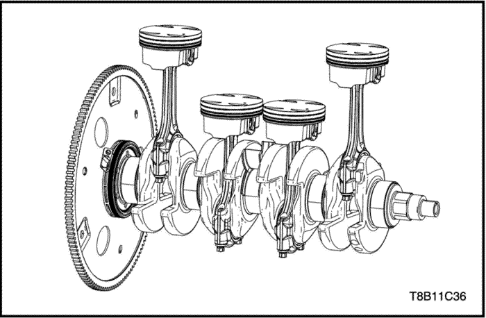
The crankshaft is composed of cast iron which has an appropriate strength. 5 main journals are supported by cylinder block, bearing cap and main bearings with a suitable oil clearance. The 3rd main bearing makes an axial clearance of crankshaft as a thrust bearing. The connecting rod is assembled at 4 pin journals each with metal bearings to change the movement from reciprocating to rotating. On the front side, there are damper pulley for belt drive and a timing sprocket for chain drive. On the rear side, there is a flywheel or a flexible plate to transport the engine torque to transmission.
The pistons are cast aluminum with crown design. They have 2 compression rings and 1 oil ring included both side rail. There is a piston pin of full floating type between piston pin bore and connecting rod pin bore, and it is fixed by retainers at both ends.
The connecting rod and rod cap are separated and assembled at crankshaft with bearings.
Lubrication System
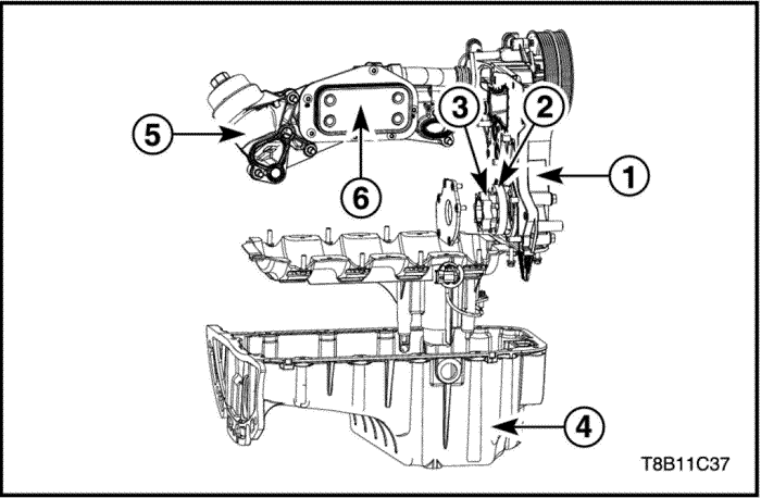
The oil pump supplies engine oil from the oil pan and feeds it to the various parts of the engine under pressure.
An oil strainer is mounted before the inlet of the oil pump to remove impurities such as clog or damage the oil pump or other engine components. When the crankshaft rotates, the oil pump driven gear rotates. It makes the space between inner rotor and outer rotor to constantly open and narrow enough to pull the oil into the main gallery of block from the oil pan.
At high engine speeds, the oil pump supplies a much higher amount of oil than required for lubrication pressure of the engine. And then, relief valve prevents amount of oil entering the engine lubrication passages.
During normal oil supply, relief valve is closed by the coil spring tension, so all of the oil is delivered to the engine parts. On the other hands, if the oil flow rate is increased, the oil pressure becomes high enough to overcome and open the force of the spring. With the consequence that, oil is returned to oil pump inlet.
For cooling the engine oil, the heat changer is located on the engine block side.
- Oil Pump (Engine Front Cover)
- Oil Pump Outer Rotor
- Oil Pump Inner Rotor
- Oil Pan
- Oil Cooler(Heat Changer)
Timing System
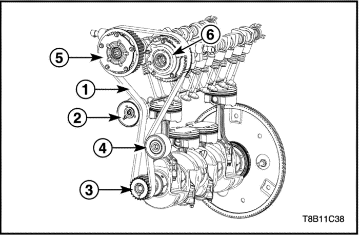
The crankshaft pulley assembled the crankshaft drives the camshaft pulleys using by the timing belt. Also, the tensioner assists the belt tension and the idler supports the timing belt by enlarging the wrap angle.
- Timing Belt
- Tensioner
- Crankshaft Gear
- Idler
- In-Camshaft Sprocket
- Out-Camshaft Sprocket
Engine Block
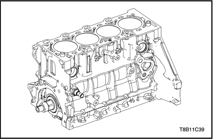
As the largest part of the engine components, the cylinder block is made of cast iron. Many related parts are assembled on the outside of cylinder block.
There are engine coolant and oil passages for cooling and lubricating in the inside of engine block.
On the inside of the engine block, the bore surface helps the piston to reciprocate, also oil cooling jet which is installed crankcase helps cooling of the piston.
The crank bore surface helps the crankshaft to rotate. Also, the cylinder block has the main bearing cap to support the crankshaft on the lower side.
| © Copyright Chevrolet Europe. All rights reserved |


