

Valve Train
Tools Required
Universal Valve Spring Compressor EN-49074
Valve Spring Compressing Adapter EN-49155
Suction Device KM-845
Removal Procedure
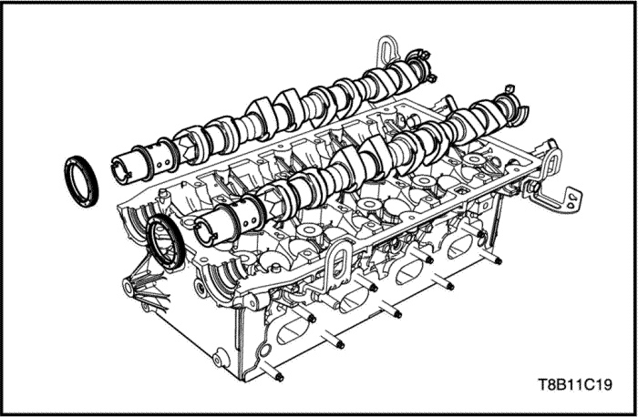
- Remove the camshaft. Refer to "UNIT REPAIR–Camshaft"
in this section.
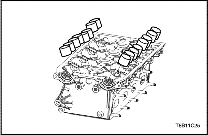
Caution : Do not scratch on the valve tappet. And it must not be used by gloves or tools except special service tools.
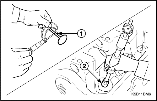
- Remove the valve tappet using by suction device(KM-845).
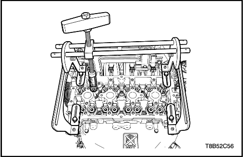
- Install the universal valve spring compressor(EN–49074) and adapter(EN-49155).
- Remove the valve key.
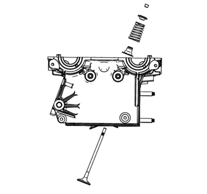
- Remove the valves, springs, retainers, and seals.
Valve Inspection
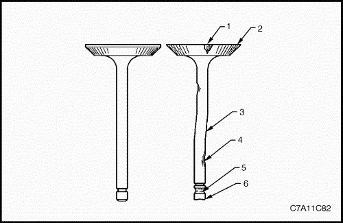
- Inspect the valve for damage from the head to tip for the following conditions.
- pitting in the valve seat area (1)
- lack of valve margin (2)
- bending in the valve stem (3)
- pitting or excessive wear in the stem (4)
- worn valve key grooves (5)
- worn valve tip (6)
- Replace the valve if any of these conditions exist.
- Inspect the valve springs. If the valve spring ends are not parallel, replace the valve spring.
- Inspect the valve spring seating surface of the valve rotators for wear or gouges. Replace as required.
Notice : Valve guide is not movable. Replace the cylinder head if it is out of specification.
- Measure the valve stem diameter and valve guide inside diameter. If it is out of specification, replace it. Refer to "Engine Specification"
in this section.
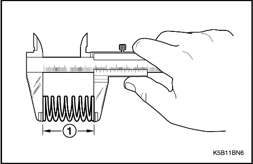
- Measure the valve spring free length. If it is out of specification, replace it. Refer to "Engine Specification"
in this section.
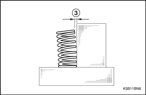
- Measure the valve spring right angles. If it is out of specification, replace it. Refer to "Engine Specification"
in this section.
Installation Procedure
- Install the valve spring, retainer, and seal.
- Install the universal valve spring compressor(EN–49074) and adapter(EN-49155).
- Install the valve key.
Caution : Do not scratch on the valve tappet. And it must not be used by gloves or tools except special service tools.
- Install the valve tappet.
- Install the camshaft. Refer to "Unit Repair-Camshaft"
in this section.
Piston / Ring / Connecting-Rod
Tools Required
Piston Installer EN-49153 (1.6L only)
Removal Procedure
Caution : Take extreme care to prevent any scratches or damage to the inner side of the cylinder, piston, and connecting rod cap bearings.
- Remove the engine oil cooler. Refer to “Oil Cooler”
in this section.
- Remove the A/C compressor. Refer to Section 7B, HVAC System.
- Remove the alternator. Refer to Section 1E2, Engine Electrical.
- Remove the starter. Refer to Section 1E2, Engine Electrical.
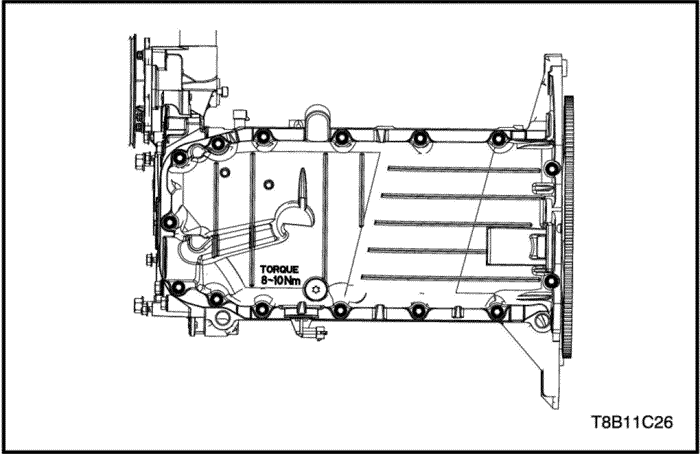
- Remove the oil pan. Refer to “Oil Pan”
in this section.
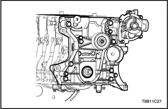
- Remove the oil pump assembly. Refer to "Oil Pump”
in this section.
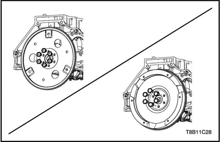
- Remove the flexible plate or flywheel. Refer to “Flexible Plate/Flywheel”
in this section.
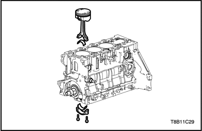
Important : Check and confirm the piston assembly sequence and the connecting rod bearing sequence, to not confuse.
- Remove the connecting-rod cap and bolts.
- Remove the piston assembly.
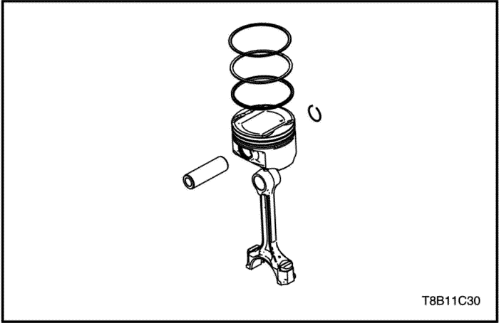
- Separate the piston pin from the piston.
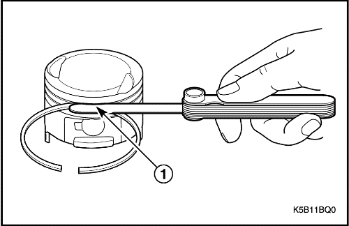
- Separate the piston ring from the piston using by expansion tool.
Inspection
- Clean the inner of the cylinder with a clean cloth.
- Inspect the inner of the cylinder if it is damaged.
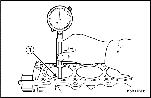
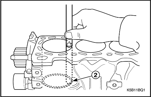
- Measure the inner diameter of the cylinder. If it is out of specification, replace it. Refer to "Engine Specification"
in this section.
- Clean the piston with a clean cloth.
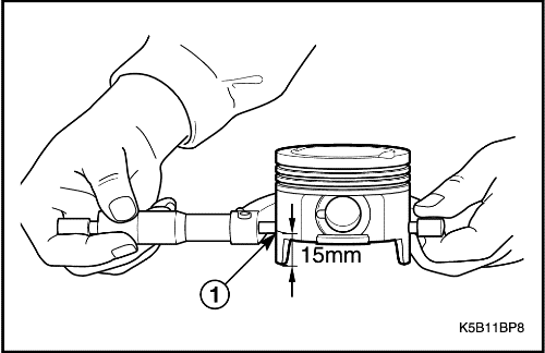
- Measure the outer diameter of the piston at the 15mm up from the bottom. If it is out of specification, replace it. Refer to "Engine Specification"
in this section.
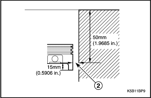
- Measure the inner diameter of the cylinder at the 50mm below from the surface of the cylinder head and the clearance of the piston at the 15mm up from the end of the piston skirt. If it is out of specification, replace it. Refer to "Engine Specification"
in this section.
- Measure the piston ring groove clearance. If the piston ring groove clearance is out of specification, replace the piston and rings. Refer to "Engine Specification"
in this section.
- Measure the piston ring gap. If the piston ring gap is out of specification, replace the piston ring. Refer to "Engine Specification"
in this section.

- Measure the piston pin. If it is out of specification, replace it. Refer to "Engine Specification"
in this section.
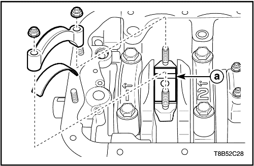
- Cut the plastic gauge(a) as the same length of the bearing width and put it on the crankshaft bearing. It should be parallel with crankshaft.
- Install the connecting rod bearing and caps. Tighten it.
Tighten
Tighten the connecting-rod caps bolts to 35+45°+15° N•m (25.8+45°+15° lb-ft)
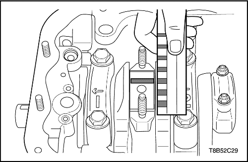
- Remove the connecting rod bearing and caps again.
- Measure the clearance of the connecting rod bearing oil as the scale of the plastic gauge. If it is out of specification, replace it. Refer to "Engine Specification"
in this section.
Installation Procedure
Caution : Take extreme care to prevent any scratches or damage to the inner side of the cylinder, piston, and connecting rod cap bearings.
- Install the piston pin from the piston.
- Install the piston ring from the piston using by expansion tool.
Important : Check and confirm the piston assembly sequence and the connecting rod bearing sequence, to not confuse.
- Install the piston assembly using by piston installer_1.6L only(EN-49153).
- Install the connecting-rod cap and bolts with bearings.
Tighten
Tighten the connecting-rod caps bolts to 35+45°+15° N•m (25.8+45°+15° lb-ft).
- Install the flexible plate or flywheel. Refer to “Flexible Plate”
or Flywheel”
in this section.
- Install the oil pump assembly. Refer to "Oil Pump”
in this section.
- Install the engine oil cooler. Refer to “Oil Cooler”
in this section.
- Install the A/C compressor. Refer to Section 7B, HVAC System.
- Install the alternator. Refer to Section 1E2, Engine Electrical.
- Install the starter. Refer to Section 1E2, Engine Electrical.
- Install the oil pan. Refer to “Oil Pan”
in this section.
Crankshaft
Tools Required
Crankshaft Rear Oil Seal Installer EN-49204
Romoval Procedure
Caution : Take extreme care to prevent any scratches, nicks or damage to inner side of the cylinder and bearings. If scratched, damage may happen to engine.
Important : Check and confirm the crankshaft caps and bearings sequences, to not confuse.
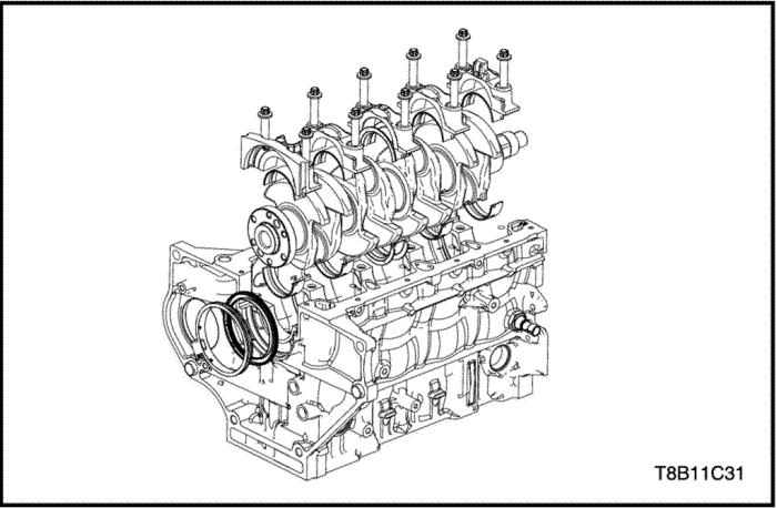
- Remove the crankshaft cap bolts.
- Remove the crankshaft caps with journal bearings.
- Remove the crankshaft.
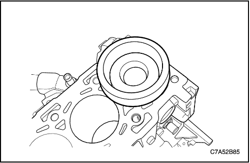
- Remove the crankshaft rear oil seal with housing.
- Detach the crankshaft rear oil seal from the housing.
Inspection
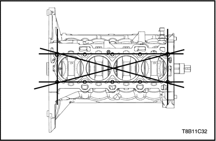
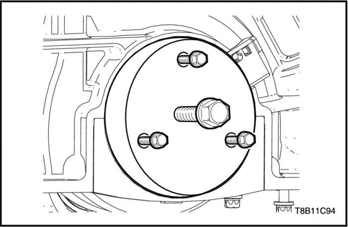
- Measure the block flatness. If it is out of specification, replace it. Refer to "Engine Specification"
in this section.
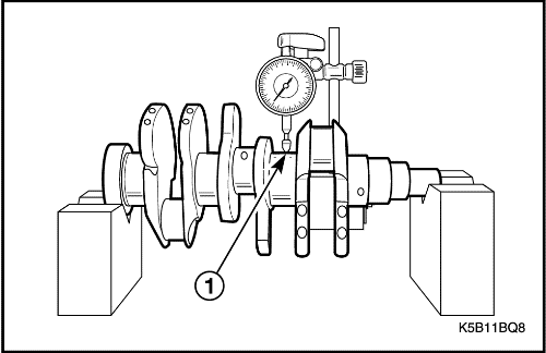
- Measure the crankshaft bending (out-of-round). If it is out of specification, replace it. Refer to "Engine Specification"
in this section.
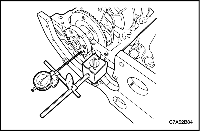
- Measure the crankshaft end play. If it is out of specification, replace it. Refer to "Engine Specification"
in this section.
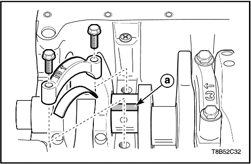
- Cut the plastic gauge(a) as the same length of the bearing width and put it on the crankshaft bearing. It should be parallel with crankshaft.
- Install the crankshaft journal bearing and cap.
- Remove the connecting rod bearing and cap again.
- Measure the clearance of the connecting rod bearing oil as the scale of the plastic gauge. If it is out of specification, replace it as a new one. Refer to "Engine Specification"
in this section.
Installation Procedure
Caution : Take extreme care to prevent any scratches, nicks or damage to inner side of the cylinder and bearings. If scratched, damage may happen to engine.
Important : Check and confirm the crankshaft caps and bearings sequences, to not confuse.
- Coat/Lubricate the crankshaft and bearings.
- Install the crankshaft with bearings in sequences.
- Install the crankshaft caps with journal bearings.
Tighten
Tighten the crankshaft cap bolts to 50+50° N•m (36.8+50° lb-ft).
- Attach the crankshaft rear oil seal to the housing.
- Install the crankshaft rear oil seal with housing using by crankshaft rear oil seal installer (EN-49204).
| © Copyright Chevrolet Europe. All rights reserved |


