MAINTENANCE AND REPAIR
ON-VEHICLE SERVICE


Fuel System Pressure Relief
Procedure
Caution : The fuel system is under pressure. To avoid fuel spillage and the risk of personal injury or fire, it is necessary to relieve the fuel system pressure before disconnecting the fuel lines.
- Remove the fuel cap.
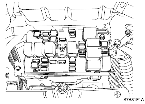
- Remove the fuel pump fuse from the engine fuse block.
- Start the engine and allow the engine to stall.
- Crank the engine for an additional 10 seconds.
Fuel Pressure Test
Tools Required
Fuel Pressure Gauge DW-100-763
Procedure
Caution : The fuel system is under pressure. To avoid fuel spillage and the risk of personal injury or fire, it is necessary to relieve the fuel system pressure before disconnecting the fuel lines.
- Relieve the fuel pressure. Refer to “Fuel System Pressure Relief”
in this section.
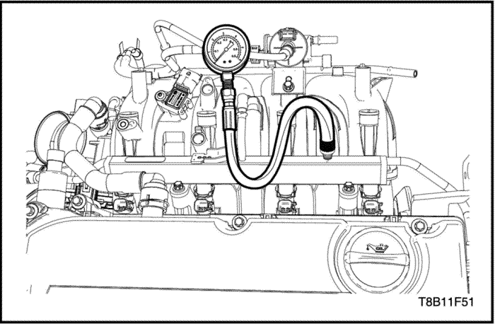
- Install the Fuel Pressure Gauge DW-100-763.
- Measure the fuel pressure.
- Fuel Pressure Spec.: 380Kpa (Battery Voltage: 13.2V)
Fuel Tank
Removal Procedure
Caution : The fuel system is under pressure. To avoid fuel spillage and the risk of personal injury or fire, it is necessary to relieve the fuel system pressure before disconnecting the fuel lines.
- Relieve the fuel pressure. Refer to "Fuel Pump & Fuel Sender" in this section.
- Disconnect the negative battery cable.
- Drain the fuel tank.
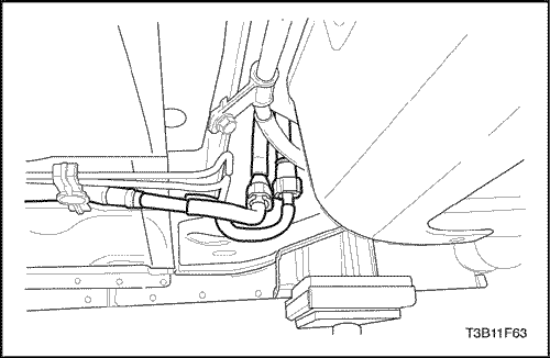
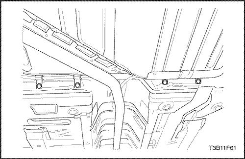
- Disconnect the parking brake cable retainer clamps
and the support along the fuel tank to provide clearance
for the tank.
- Remove the fuel tank filler tube clamp at the fuel tank.
- Disconnect the fuel tank filler tube.
- Disconnect the fuel tank filler tube at the fuel tank.
- Disconnect the canister vapor tube at control valve
vapor tube.
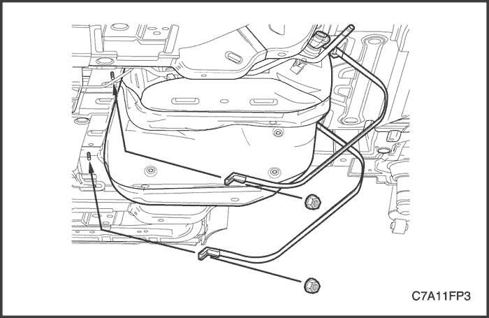
- Disconnect the fuel pump harness connector at the
right rear corner of the fuel tank.
- Disconnect the fuel inlet line near the right front of the fuel tank.
- Disconnect the wiring harness clips and the fuel line
clips as needed.
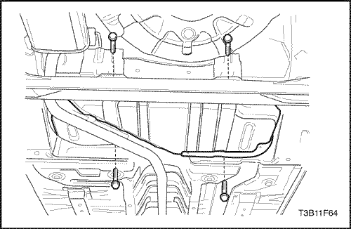
- Support the fuel tank.
- Remove the fuel tank retaining bolts.
- Carefully lower the fuel tank.
- Remove the fuel tank.
- Transfer any parts as needed.
Installation Procedure
- Raise the fuel tank into position.
- Install the fuel tank mounting bolts.
Tighten
Tighten the fuel tank retaining bolts to 20 N•m
(15 lb-ft).
- Connect the fuel outlet line.
- Connect the wiring harness clips and the fuel line
clips as needed.
- Connect the fuel pump electrical connector.
- Connect the fuel vapor line.
- Connect the fuel tank filler tube and fuel tank vent tube.
- Install the fuel tank filler tube clamp at the fuel tank.
- Install the parking brake cable retainer clamps and
the support.
Tighten
Tighten the parking brake cable retainer clamps to
10 N•m (89 lb-in ).
- Connect the negative battery cable.
- Fill the fuel tank.
- Perform a leak check of the fuel tank and the fuel
line connections.
Fuel Pump Assembly
Tools Required
EN-49090 Remover/Installer-Fuel Pump Lock Ring
Removal Procedure
Caution : The fuel system is under pressure. To avoid fuel spillage and the risk of personal injury or fire, it is necessary to relieve the fuel system pressure before disconnecting the fuel lines.
- Relieve the fuel pressure.
- Disconnect the negative battery cable.
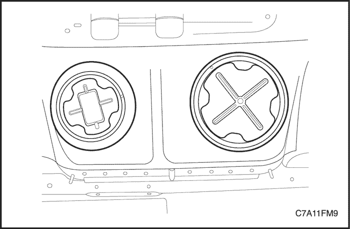
- Remove the rear seat. Refer to Section 9H, Seats.
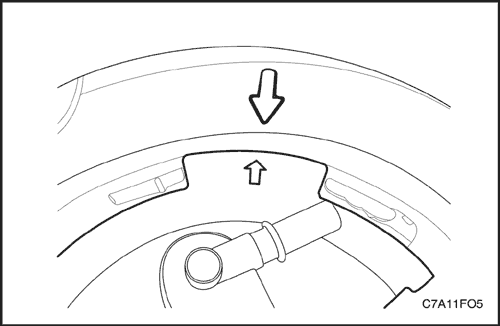
- Remove the fuel pump access cover.
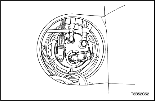
- Loosen the locking by pushing the fuel pump electrical connector tap.
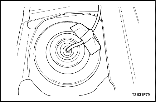
- Disconnect the electrical connector at the fuel pump assembly.
- Disconnect the fuel outlet line.
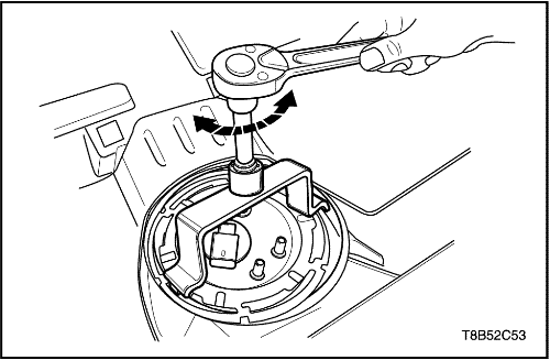
- Remove the fuel pump lock ring by using remover/installer-fuel pump lock ring(EN-49090).
- Remove the fuel pump.
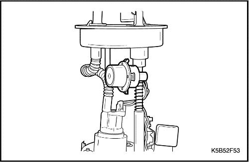
- Disconnect the insulator.
- Remove the fuel sender assembly.
Installation Procedure
Caution : Be careful to install the fuel sender to fuel pump housing exactly. If not installed exactly, fuel indicating may be incorrect.
- Install the fuel sender assembly.
- Connect the fuel sender insulator.
- Install the fuel pump to fuel tank.
- Install the fuel pump lock ring by using remover/installer-fuel pump lock ring (EN-49090).
- Connect the electrical connector at the fuel pump assembly.
- Tighten the locking by pushing the fuel pump electrical connector tap.
- Connect the fuel outlet line.
- Install the fuel pump access cover.
- Connect the negative battery cable.
- Perform an operational check of the fuel pump.
- Install the rear seat Refer to Section 9H, Seats.
Fuel Filter
Removal Procedure
Caution : The fuel system is under pressure. To avoid fuel spillage and the risk of personal injury or fire, it is necessary to relieve the fuel system pressure before disconnecting the fuel lines.
- Relieve the fuel pressure.
- Disconnect the negative battery cable.
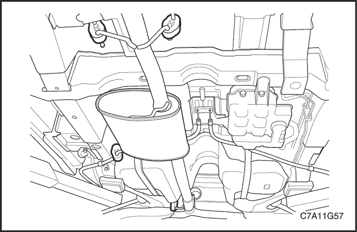
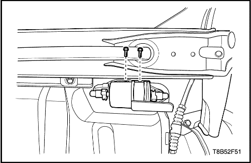
- Disconnect the inlet/outlet fuel lines by moving the line connector lock forward and pulling the hose off of the fuel filter tube.
- Remove the fuel filter bracket bolts.
- Remove the fuel filter.
Installation Procedure
- Install the fuel filter.
- Install the fuel filter bracket bolts.
Tighten
Tighten the fuel filter bracket bolts to 4 N•m (35.4 lb-in).
- Connect the inlet/outlet quick connector lines.
- Connect the negative battery cable.
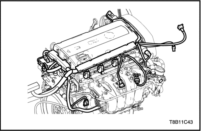
Fuel Rail and Injectors
Removal Procedure
Caution : The fuel system is under pressure. To avoid fuel spillage and the risk of personal injury or fire, it is necessary to relieve the fuel system pressure before disconnecting the fuel lines.
- Relieve the fuel pressure system. Refer to “Fuel System Pressure Relief”
in this section.
- Disconnect the battery negative cable.
- Disconnect the injector’s connectors.
- Disconnect the fuel line from the fuel rail and put a dust cap to avoid strange materials.
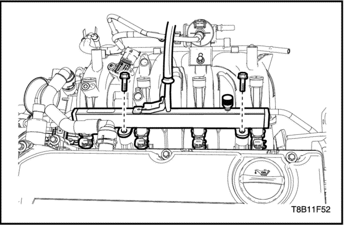
- Remove the fuel rail tightening bolts.
- Remove the fuel rail with the injectors.
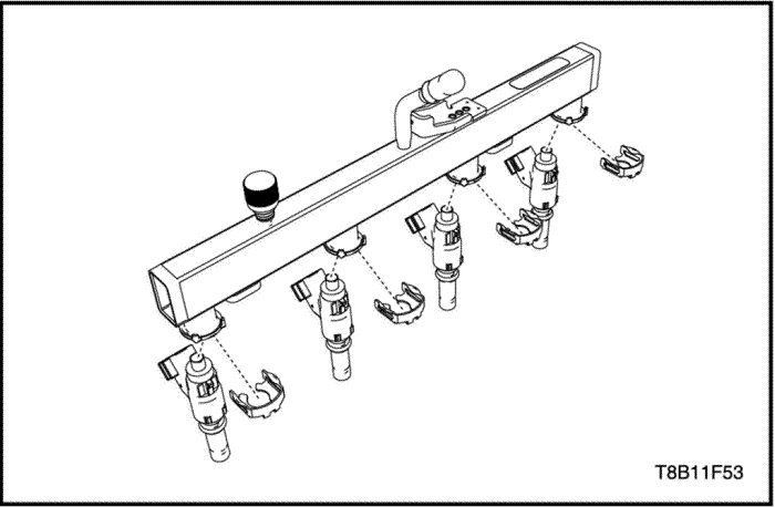
- Detach the fuel injector retainer clips.
- Detach the fuel injectors by pulling down and out.
- Discard the fuel injector O-rings.
Installation Procedure
- Attach the fuel injector O-rings.
- Attach fuel injectors to the fuel rail.
- Attach the fuel injector retainer clips.
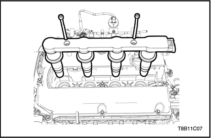
- Install the fuel rail with the injectors to the intake manifold.
- Install the fuel rail tightening bolts.
Tighten
Tighten the fuel rail tightening bolt to 8 N•m (70.8 lb-in).
- Connect the fuel line from the fuel rail and put a dust cap to avoid strange materials.
- Connect the fuel injector connectors.
- Connect the battery negative cable.
Ignition Coil
Tools Required
Remover/Installer KM-6009
Removal Procedure
- Disconnect the battery negative cable.
- Detach the ignition coil cover.
- Disconnect the ignition coil connector.
- Remove the ignition coil bolts.
Tighten
Tighten the ignition coil bolt to 8 N•m (70.8 lb-in).
- Install the remover/installer KM-6009.
- Remove the ignition coil.
Engine Coolant Temperature (ECT1) Sensor 1
Removal Procedure
- Disconnect the battery negative cable.
- Drain the engine coolant. Refer to Section 1D, Engine Cooling.
- Disconnect the ECT sensor connector.
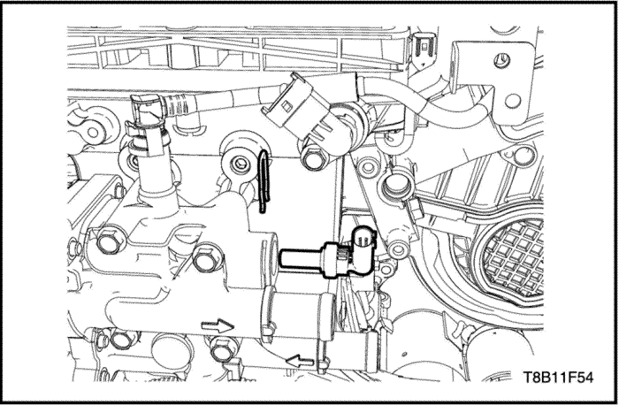
- Detach the ECT retaining clip.
- Detach the ECT from the coolant distributor.
Installation Procedure
- Attach the ECT to the coolant distributor.
- Attach the ECT retaining clip.
- Connect the ECT sensor connector.
- Refill the engine coolant. Refer to Section 1D, Engine Cooling.
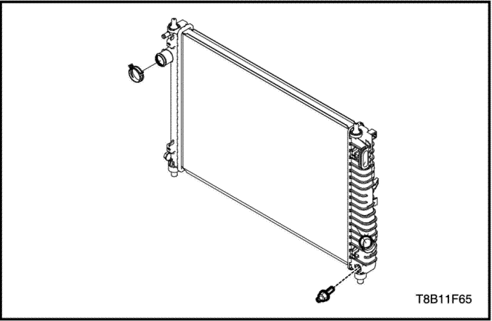
Engine Coolant Temperature (ECT) Sensor 2
Removal and Installation Procedure
- Disconnect the battery negative cable.
- Drain the engine coolant. Refer to Section 1D, Engine Cooling.
- Disconnect the ECT2 sensor connector.
- Remove the ECT2 sensor from the radiator.
Tighten
Tighten the ECT2 sensor to 20 N•m (15 lb-ft).
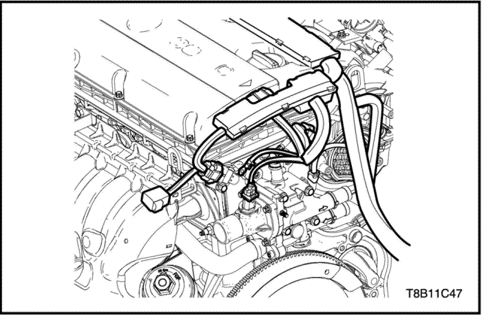
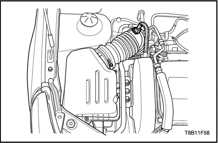
Electric Throttle Controller (ETC)
Removal Procedure
- Disconnect the battery negative connector.
- Drain the engine coolant. Refer to Section 1D, Engine Cooling.
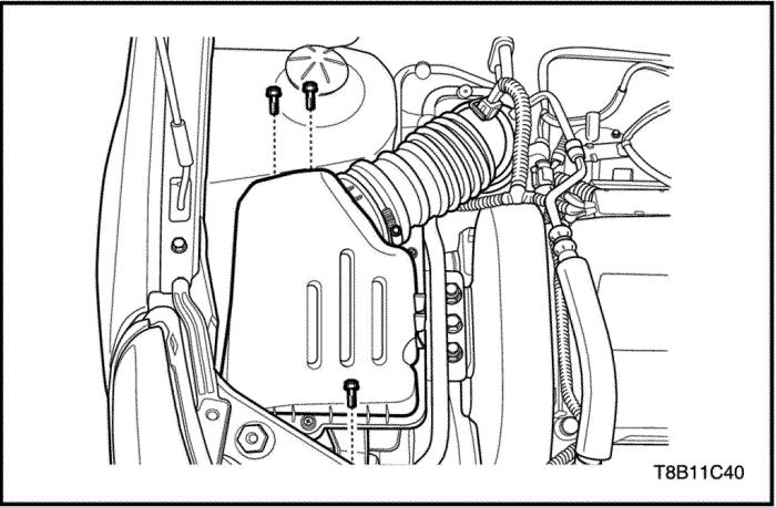
- Remove the air cleaner assembly. Refer to Section 1C2, Engine Mechanical - 1.4L (G14D).
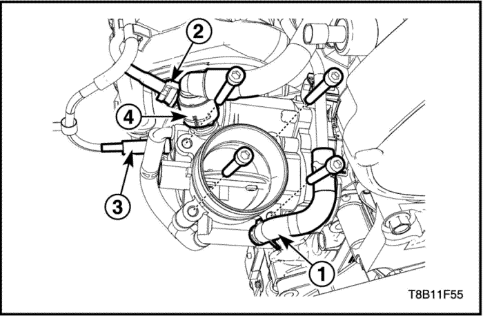
- Disconnect the ETC connector.
- Disconnect the coolant inlet hose(1).
- Disconnect the coolant outlet hose(2).
- Disconnect the EVAP hose(3).
- Detach the PCV hose(4).
- Remove the ETC tightening bolts.
- Remove the ETC with the seal ring.
Installation Procedure
- Install the ETC with the seal ring.
- Install the ETC tightening bolts.
Tighten
Tighten the ETC tightening bolts to 8 N•m (70.8 lb-in).
- Connect the coolant inlet hose(1).
- Connect the coolant outlet hose(2).
- Connect the EVAP hose(3).
- Attach the PCV hose(4).
- Connect the ETC connector.
Front Heated Oxygen Sensor (HO2S1)
Tools Required
Oxygen Sensor Remover/Installer EN-48259
Removal Procedure
Notice : The oxygen sensor uses a permanently attached pigtail and connector. This pigtail should not be removed from the oxygen sensor. Damage or removal of the pigtail or the connector could affect proper operation of the oxygen sensor. Take care when handling the oxygen sensor. Do not drop the oxygen sensor.
Caution : Allow the engine to cool before removing the oxygen sensor. Removal of the oxygen sensor when the engine is hot may damage the threads in the exhaust manifold.
- Disconnect the battery negative cable.
- Disconnect the HO2S1 connector.
- Install the EN-48259.
- Remove the HO2S1.
Installation Procedure
Important : A special anti–seize compound is used on the oxygen sensor threads. This compound consists of a liquid graphite and glass beads. The graphite will burn away, but the glass beads will remain, making the sensor easier to remove. New or service sensors will already have the compound applied to the threads. If a sensor is removed from any engine and if for any reason it is to be reinstalled, the threads must have anti–seize compound applied before reinstallation.
- Coat the threads of the HO2S1 with an anti–seize compound, if needed.
- Install the HO2S1 into the exhaust manifold.
Tighten
Tighten the HO2S1 to 40 N•m (29.5 lb-ft).
Rear Heated Oxygen Sensor (HO2S2)
Tools Required
Oxygen Sensor Remover/Installer EN-48259
Removal Procedure
Notice : The oxygen sensor uses a permanently attached pigtail and connector. This pigtail should not be removed from the oxygen sensor. Damage or removal of the pigtail or the connector could affect proper operation of the oxygen sensor. Take care when handling the oxygen sensor. Do not drop the oxygen sensor.
Caution : Allow the engine to cool before removing the oxygen sensor. Removal of the oxygen sensor when the engine is hot may damage the threads in the front exhaust pipe.
- Disconnect the battery negative cable.
- Disconnect the HO2S2 connector.
- Install the EN-48259.
- Remove the HO2S2.
Installation Procedure
Important : A special anti–seize compound is used on the oxygen sensor threads. This compound consists of a liquid graphite and glass beads. The graphite will burn away, but the glass beads will remain, making the sensor easier to remove. New or service sensors will already have the compound applied to the threads. If a sensor is removed from any engine and if for any reason it is to be reinstalled, the threads must have anti–seize compound applied before reinstallation.
- Coat the threads of the HO2S2 with an anti–seize compound, if needed.
- Install the HO2S2 into the front exhaust pipe.
Tighten
Tighten the HO2S2 to 40 N•m (29.5 lb-ft).
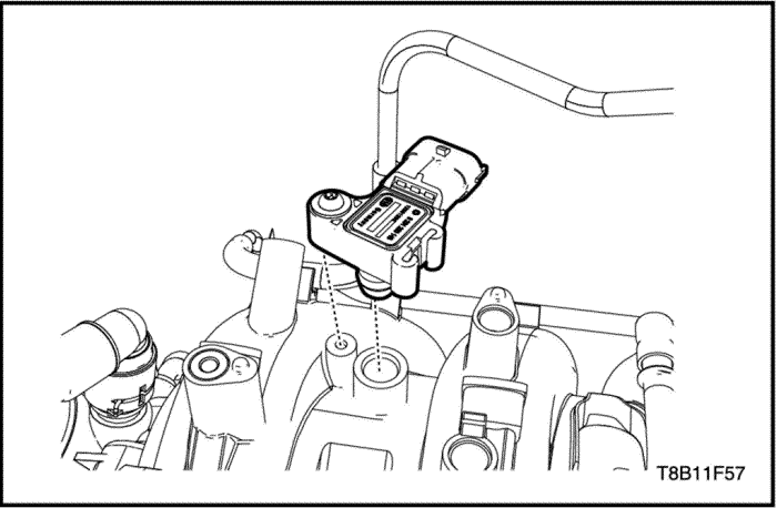
Manifold Air Pressure (MAP) Sensor
Removal and Installation Procedure
- Disconnect the battery negative cable.
- Disconnect the MAP sensor connector.
- Remove the MAP sensor connector.
Tighten
Tighten the MAP sensor screw to 8 N•m (70.8 lb-in).
Intake Air Temperature (IAT) Sensor
Removal and Installation Procedure
- Disconnect the battery negative cable.
- Disconnect the IAT sensor connector.
- Remove the IAT sensor.
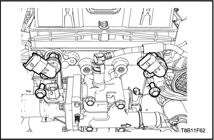
Camshaft Position Actuator Solenoid Valve
Removal Procedure
- Disconnect the battery negative cable.
- Disconnect the camshaft position valve connectors.
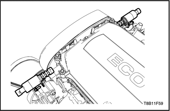
- Remove the camshaft position valve bolt.
- Remove the camshaft position valve with seal ring.
Installation Procedure
- Coat the seal ring with the clean engine oil.
- Install the camshaft position valve.
- Install the camshaft position valve bolt.
Tighten
Tighten the camshaft position valve bolt to 6 N•m (53.1 lb-in).
- Connect the camshaft position valve connectors.
- Connect the battery negative cable.
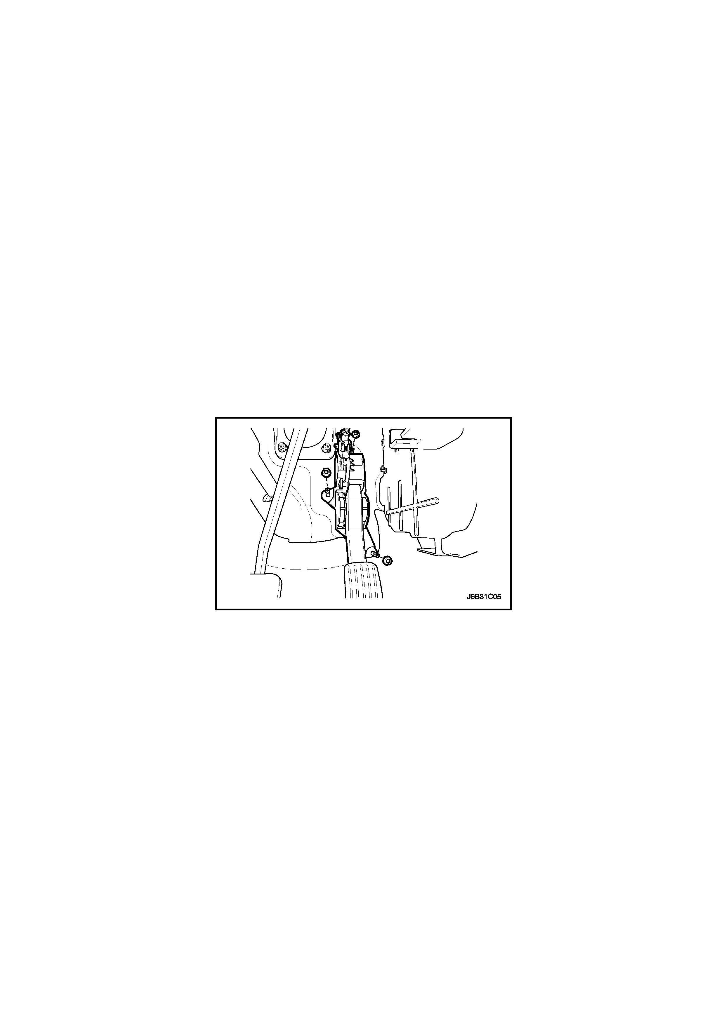
Accelator Pedal Module (APM)
Removal and Installation Procedure
- Disconnect the battery negative cable.
- Disconnect the accelerator pedal module (APM) connector from the APM.
- Remove the nuts, three places, attaching the APM to the APM support bracket.
Tighten
Tighten the accelerator pedal module retaining nuts to 12 N•m (8.8 lb-ft).
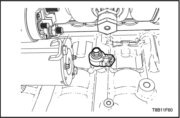
Knock Sensor
Removal and Installation Procedure
- Disconnect the battery negative cable.
- Remove the knock sensor tightening bolt.
- Remove the knock sensor.
Tighten
Tighten the knock sensor tightening bolt to 20 N•m (14.7 lb-ft).
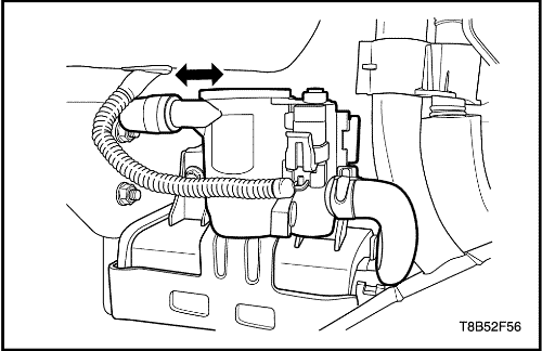
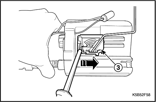
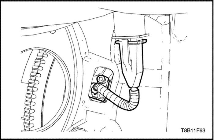
Evaporative Emission (EVAP) Canister Vent
Removal Procedure
- Disconnect the negative battery cable.
- Disconnect the EVAP canister vent solenoid valve connector.
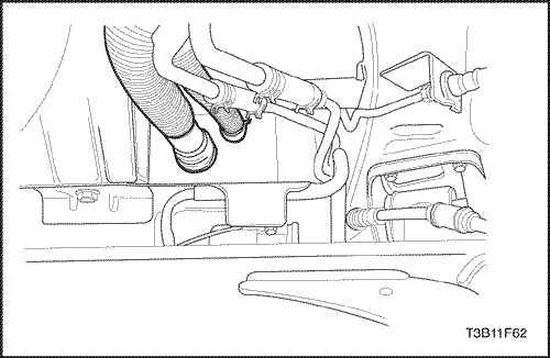
- Disconnect the EVAP canister vent hose.
- Remove the EVAP canister vent assembly pushing it to the left side.
Installation Procedure
- Install the EVAP canister vent assembly pushing it to the right side.
- Connect the EVAP canister vent hose.
- Connect the EVAP canister vent solenoid valve connector.
- Connect the negative battery cable.
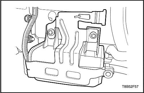
Evaporative Emission (EVAP) Canister
Removal Procedure
- Remove the EVAP canister vent. Refer to "Evporative Emission (EVAP) Canister Vent"
in this section.
- Disconnect the inlet & outlet hose from the EVAP canister.
- Remove the EVAP canister bracket retaining bolt.
- Remove the EVAP canister.
Installation Procedure
- Install the EVAP canister.
- Install the EVAP canister bracket retaining bolt.
Tighten
Evaporative Emission Canister Bracket Retaining Bolt to 8 N•m (71 lb-in).
- Connect the inlet & outlet hose to the EVAP canister.
- Install the EVAP canister vent. Refer to "Evporative Emission (EVAP) Canister Vent"
in this section.
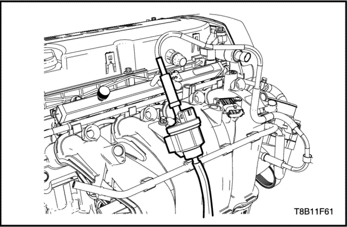
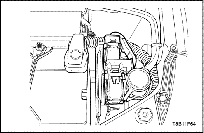
EVAP Canister Purge Valve
Removal and Installation Procedure
Caution : The fuel system is under pressure. To avoid fuel spillage and the risk of personal injury or fire, it is necessary to relieve the fuel system pressure before disconnecting the fuel lines.
- Disconnect the battery negative cable.
- Disconnect the EVAP canister purge valve upper and lower hoses.
- Disconnect the EVAP canister purge valve connector.
- Detach the EVAP canister purge valve.
Camshaft Position (CMP) Sensor
Removal and Installation Procedure
- Disconnect the battery negative cable.
- Disconnect the CMP sensor connectors.
- Remove the CMP sensor tightening bolts.
Tighten
Camshaft position sensor mounting bolt to 6.5 N•m (57.5 lb-in).
- Remove the CMP sensor.
Crankshaft Position Sensor (CKP) Sensor
Removal and Installation Procedure
- Disconnect the battery negative cable.
- Remove the starter. Refer to Section 1E, Engine Electric.
- Remove the CKP sensor tightening bolt.
- Remove the CKP sensor.
Tighten
Tighten the CKP sensor bolt to 4.5 N•m (39.8 lb-in).
ECM
Removal and Installation Procedure
- Disconnect the battery negative cable.
- Unlock the ECM connector locking lever.
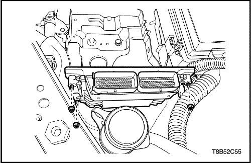
- Remove the ECM retaining nuts.
Tighten
Tighten the ECM retaining nuts to 8 N•m (70.8 lb-in).
- Remove the ECM.
| © Copyright Chevrolet Europe. All rights reserved |


