SECTION 2D
REAR SUSPENSION
SPECIFICATIONS
Fastener Tightening Specifications
|
Application
|
N•m
|
Lb-Ft
|
|
Shock Absorber-to-Body Bolts (upper)
|
50
|
37
|
|
Shock Absorber-to-Axle Bolt (Lower)
|
72
|
53
|
|
Shock Absorber Piston Rod Nut
|
20
|
15
|
|
Rear Axle Mounting Bolt
|
115
|
85
|
|
Rear Axle Mounting Bracket Bolt
|
70
|
52
|
|
Rear Wheel Bearing Spindle to Axle Fixing Nut
|
80
|
59
|
|
Rear Hub Caulking Nut
|
190
|
140
|
CONPONENT LOCATOR
Rear Suspension
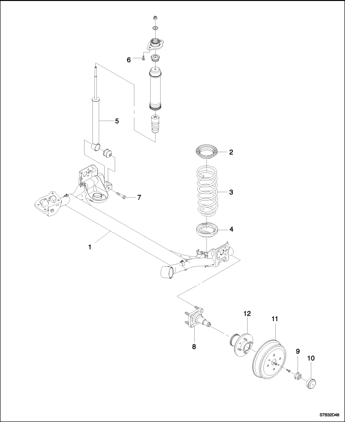


- Rear axle
- Spring upper Insulator
- Coil spring
- Spring lower Insulator
- Shock absorber
- Shock absorber upper bolt
- Shock absorber lower bolt
- Wheel bearing spindle
- Caulking nut
- Spindle cap
- Brake drum
- Rear hub unit
SPECIAL TOOLS
Special Tools Table
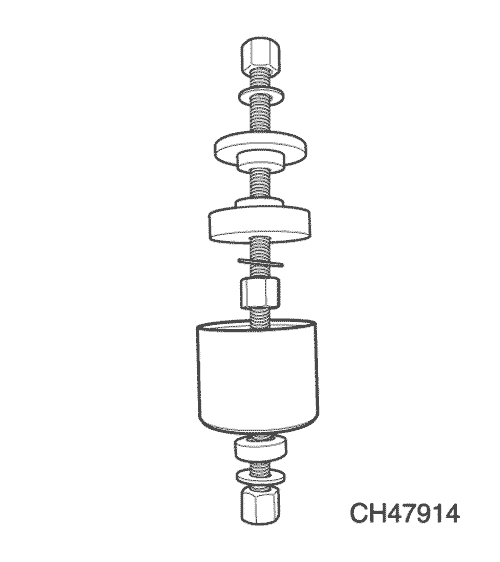
|
CH47914
Hub Bearing Remover/Installer (Bearing and drum assembled type only)
|
DIAGNOSIS
Excessive Friction Test
Check excessive friction in the rear suspension as follows:
- With the aid of a helper, lift up on the rear bumper and
raise the vehicle as high as possible. Slowly release
the bumper and allow the car to assume normal trim
height.
- Measure the distance from the floor to the center of
the bumper.
- Push down on the bumper, release slowly, and allow
the car to assume normal trim height.
- Measure the distance from the floor to the center of
the bumper.
The difference between the two measurements should
be less than 12.7 mm (0.50 inch). If the difference exceeds
this limit, inspect the control arms for damage or
wear.
MAINTENANCE AND REPAIR
ON-VEHICLE SERVICE
Shock Absorber
Removal Procedure
Notice : Remove only one shock at a time when both
shocks are being replaced. Suspending the rear axle at
full length can result in damage to brake lines and
hoses.
- Remove the shock absorber-to-body bolts (upper).
Important : When lifting the vehicle with a body hoist, it
will be necessary to support the rear axle with adjustable
jack stands.
- Raise the vehicle and support the rear axle assembly.
- Remove the lower shock absorber-to-axle bolt.
Remove the shock absorber.
Installation Procedure
Important : It will be necessary to bring the axle assembly
to trim height prior to tightening the shock absorber
attachment bolts.
- Insert the lower shock absorber-to-axle bolt through
the shock absorber lower attachment bracket and
into the axle.
- Lower the vehicle enough to guide the upper shock
stud on the body opening and loosely install the
attaching bolts.
Tighten
Tighten the lower shock absorber-to-axle bolt to 72 N•m (53 lb-ft) and upper shock absorber-to-body bolt to 50 N•m (37 lb-ft).
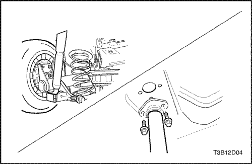
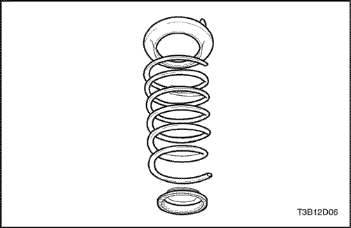
Springs and Insulators
Caution :
When removing the rear springs, do not
use a twin-post type hoist. The tendency of the rear
axle assembly to swing when certain fasteners are
removed may cause it to slip from the hoist. This
may result in personal injury. Perform the operation
on the floor if necessary.
Removal Procedure
- Raise and suitably support the vehicle. Use a frame
contact hoist if possible and support the rear control
arms with jack stands. If it becomes necessary to lift
the vehicle with a twin-post hoist, lift the body and
support the control arms with jack stands.
- Remove the wheel. Refer to Section 2E, Tires
and Wheels.
- Remove the right and the left shock absorber bolts.
Refer to "Shock Absorber"
in this section.
- Lower the rear axle and remove the springs and the
top insulator.
Installation Procedure
Important : Prior to installing the springs, it will be necessary
to install the upper insulators to the body with
adhesive to keep them in position while raising the axle
assembly and the springs.
- Install the upper insulator and seat the lower bumper.
- Install the springs and raise the axle.
- Install the shock absorbers. Refer to "Shock Absorber"
in this section.
Important : It will be necessary to bring the axle assembly
to trim height prior to tightening the shock absorber
attachment bolts.
- Install the wheel. Refer to Section 2E, Tires and
Wheels.
- Remove the jack stands and lower the vehicle.
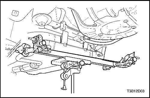
Rear Axle Assembly
Removal Procedure
- Raise and suitably support the vehicle.
- Remove the rear wheels. Refer to Section 2E, Tires and
Wheels.
- Disconnect the parking brake. Refer to Section 4G,
Parking Brake.
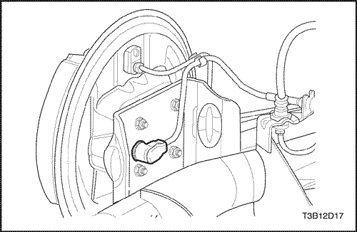
- Disconnect the ABS sensor line.
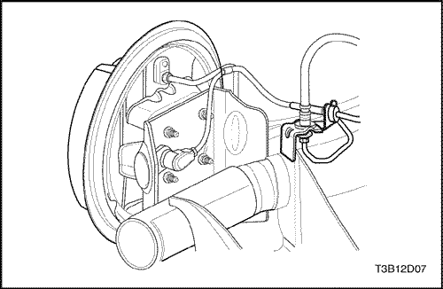
- Disconnect the brake pipes from the brake hoses at the rear axle brackets by removing the cap screws and the retaining clip. Cap or tape the brake hose openings to prevent entry of foreign matter. Unclip the brake hose from the rear axle brackets.
- Place support jacks under the arms of the rear axle
and raise the rear axle arms slightly.
Remove the shock absorbers. Refer to "Shock Absorbers"
in this section.
- Remove the shock absorbers. Refer to “Shock Absorbers”
in this section.
- Lower the support jacks and remove the rear
springs. Refer to "Springs and Insulators"
in this section.
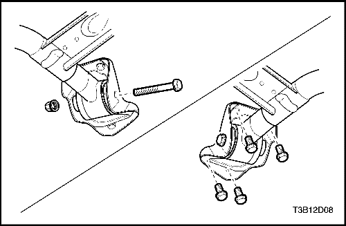
- Remove the rear axle mounting bolts (left) and the rear axle mounting bracket bolts (right) from
the underbody. Pry the rear axle slightly with a
screwdriver, if required.
- Remove the rear axle.
Installation Procedure
- Raise the rear axle and loosely fasten it to the vehicle
underbody mountings with the rear axle-to-body
bracket bolt.
- Install the rear springs and insulators. Refer to "Springs and Insulators"
in this section.
- Raise the rear axle arm with the support jacks. Attach
the shock absorber to the axle with the lower
attachment bolt. Refer to "Shock Absorbers"
in this section.
- Connect the brake pressure hoses into the bracket on the rear axle. Mount the retaining clips. Connect the brake pipes to the brake hoses.
- Install the parking brake. Refer to Section 4G,
Parking Brake.
- Lower the vehicle slightly and install the rear wheels.
Refer to Section 2E, Tires
and Wheels.
- At curb height, tighten the rear axle-to-body bracket bolt (left)and the rear axle mounting bracket bolts (right).
Tighten
Tighten the rear axle-to-body bracket bolt to
115 N•m (85 lb-ft) and the rear axle mounting bracket bolts to 70 N•m (52 lb-ft)
- Adjust the rear wheel brakes. Bleed the brake system
and check for leaks. Refer to Section 4A, Hydraulic Brakes.
- Connect the ABS sensor line.
- Adjust the parking brake. Refer to SectIon 4G,
Parking Brake.
- Lower the vehicle completely.nuts
Wheel Bearing Spindle/Rear Hub Unit
Removal Procedure
- Raise and suitably support the vehicle.
- Remove the wheel. Refer to Section 2E, Tires
and Wheels.
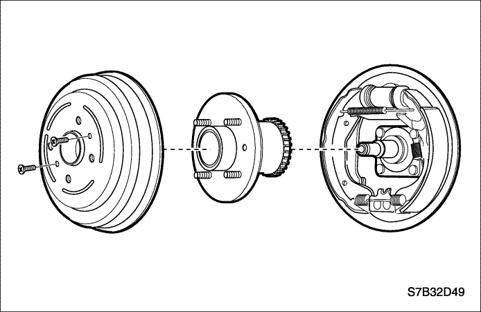
Notice : Do not hammer on the brake drum. Damage to
the bearing could result.
- Remove the detent screws, brake drum and rear hub unit.
- Loosen the parking brake cable. Refer to Section 4G,
Parking Brake.
- Disconnect the ABS sensor line, if equipped ABS.
- Remove the wheel bearing spindle to rear axle nuts.
- Remove the rear wheel bearing spindle.
Installation Procedure
- Install the wheel bearing spindle with the nuts and position the rear hub unit.
Tighten
Tighten the wheel bearing spindle nuts to 80 N•m (59 lb-ft).
- Connect the ABS sensor line.
- Install the brake drum and tighten the brake drum detent screw.
Tighten
Tighten the brake drum detent screws to 4 N•m (35 lb-in).
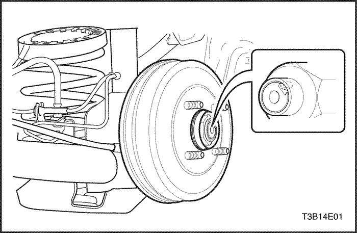
- Install the rear hub caulking nut.
Tighten
Tighten the rear hub caulking nut to 190 N•m (140 lb-ft).
- Mount the rear wheel. Refer to Section 2E, Tires
and Wheels.
- Adjust the parking brake. Refer to Section 4G, Parking
Brake.
- Lower the vehicle.
UNIT REPAIR
Hub Bearing
(Bearing and drum assembled type only)
Tools Required
CH47914 Hub Bearing Remover/Installer
Disassembly Procedure
- Raise and suitably support the vehicle.
- Remove the drum from the vehicle. Refer to Section 4E, Rear Drum Brakes.
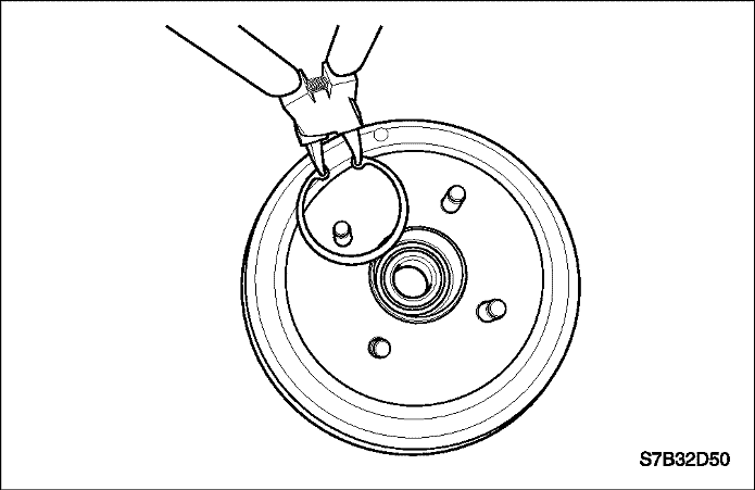
- Remove the wheel bearing retaining clip.
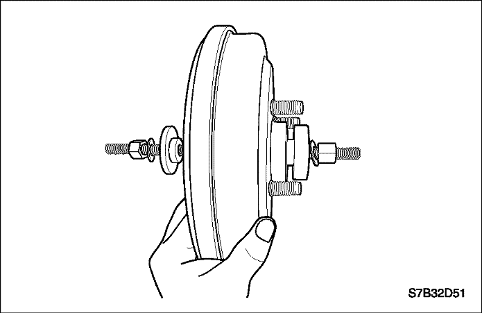
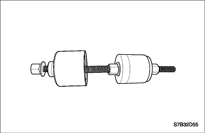
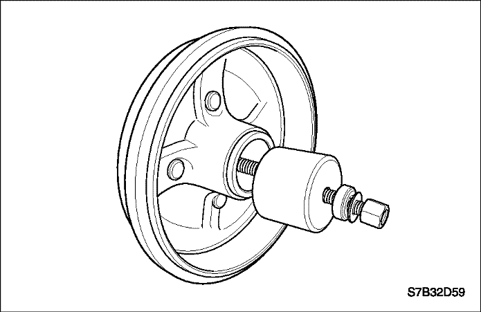
- Insert the threaded rod through the bearing.
- Place the large (CH47914-2) and small (CH47914-3) spacers on the rod.
Important : The large and small spacers on the rod in a manner that the raised portion of the flat washer fits inside the inner bearing race.
- Place a flat washer and hex nut on the threaded rod behind each spacer.
- Hand-tighten the hex nuts until the large and small spacers are held in place.
- Thread the hex nuts until the majority of the rod's length protrudes from the outer face of the drum.
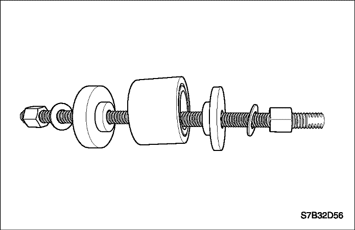
- Apply a light coat of pressure lube on the threaded rod.
- Place the receiver, thrust bearing, flat washer, and hex nut on the threaded rod from the outside of the drum.
Important : Ensure that the thrust bearing is placed between the receiver and flat washer.
- Fix the drum and tool assembly in a vise.
- Tighten the hex nut until the bearing is pulled free from the brake drum.
- Remove the hub bearing from the tool(CH47914).
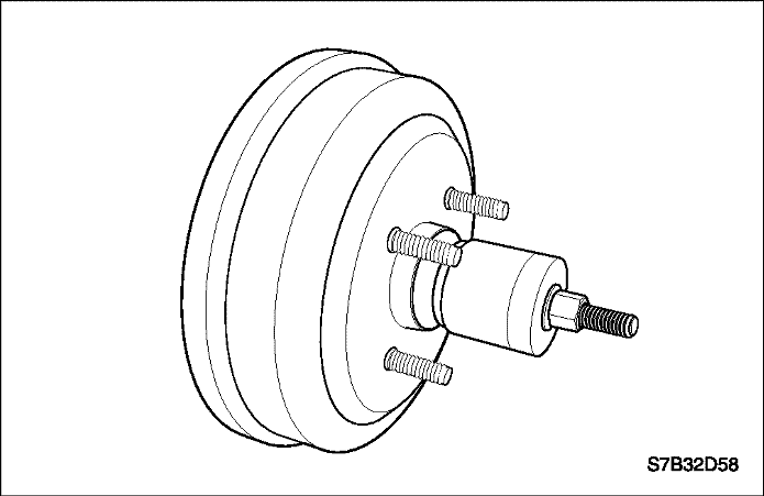
Assembly Procedure
- Place the rear brake drum bearing on the tool(CH47914).
- Place the large (CH47914-2) and small (CH47914-3) spacers, flat washers and hex nuts on either side of the hub bearing. Important: Place both spacers on the rod in a manner that the raised portion of the flat washer fits inside the inner bearing race.
- Hand-tighten the hex nuts until the large and small spacers are held in place.
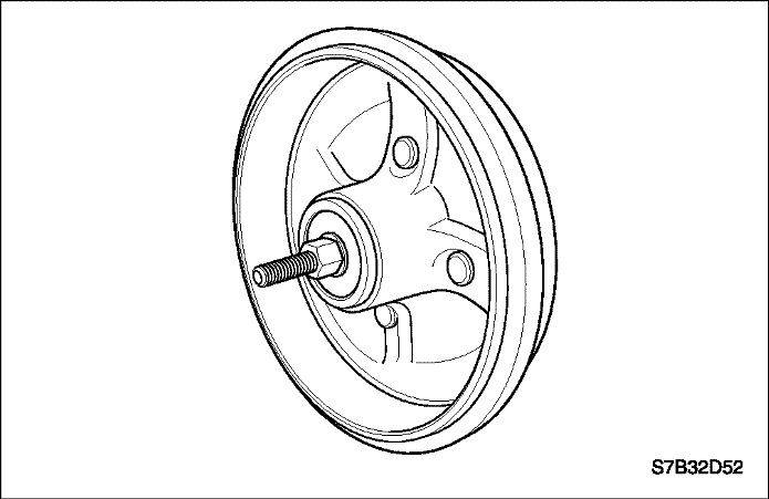
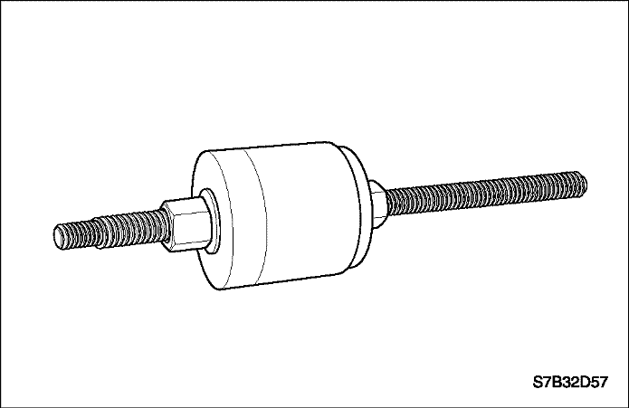
- Thread the hex nuts so that the large spacer is located towards the end of the threaded rod.
- Insert the threaded rod into the rear brake drum, so the small spacer is placed into the drum first.
- Apply a light coat of pressure lube (J23444-A) on the threaded rod.
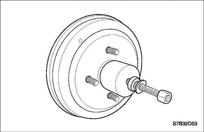
- Place the receiver, thrust bearing, flat washer, and hex nut on the threaded rod.
Important : Ensure that the thrust bearing is placed between the receiver and flat washer.
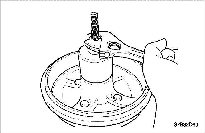
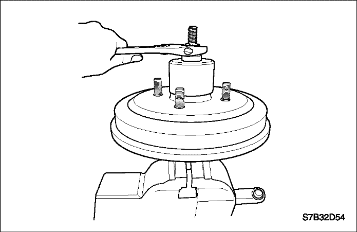
- Fix the drum and tool assembly in a vise.
- Tighten the hex nut until the hex nut stops turning.
Important : Once the hex nut becomes difficult to turn, the bearing is fully seated in the drum. Seating the bearing does not require a lot of force.
- Remove the tool(CH47914) from the drum.
GENERAL DESCRIPTION AND SYSTEM OPERATION
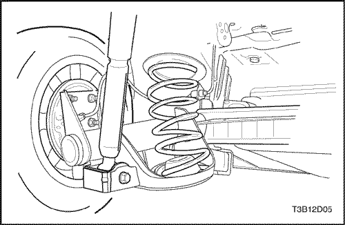
Rear Suspension
General Description
The rear suspension consists of an axle with trailing
arms and a twisting cross beam, two coil springs, two
shock absorbers, two upper spring insulators, and two
spring compression bumper. The axle support assembly
attaches to the underbody through a rubber bushing located
at the front of each of the control arms. The brackets
are integral with the underbody side rails. The axle
structure maintains the relationship of the wheels to the
body. A serviceable stabilizer shaft, incorporated with
the axle beam, attaches to each of the control arms.
Each coil spring is retained between a seat in the underbody
and a seat welded to the top of the rear axle control
arm. The coil spring lower end rests on a compression
bumper in the welded bracket on top of the rear axle,
while a rubber insulator is used to isolate the coil spring
upper end from the vehicle underbody seat.


