SECTION 4C
POWER BOOSTER
SPECIFICATIONS
Fasrener Tightening Specifications
|
Application
|
N•m
|
Lb-Ft
|
Lb-In
|
|
Booster and Support Bracket-to-Dash Panel Nuts
|
24
|
18
|
-
|
|
Booster Pushrod Hex Nut
|
16
|
12
|
-
|
|
Booster-to-Support Bracket Nuts
|
12
|
9
|
-
|
|
Master Cylinder Attaching Nuts
|
24
|
18
|
-
|
DIAGNOSIS
Power Booster Functional Check
- With the engine stopped, eliminate the vacuum in the
booster by pumping the brake pedal several times.
- Push the pedal down and hold it in this position.
- Start the engine.
- The booster is OK if the pedal drops further because
of extra force produced.
- If the brake pedal does not drop, the vacuum system
(vacuum hoses, check valve, etc.) is probably defective
and should be checked.
- If no defect is revealed by checking the vacuum system,
the defect is in the booster itself.
MAINTENANCE AND REPAIR
ON-VEHICLE SERVICE
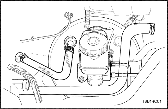


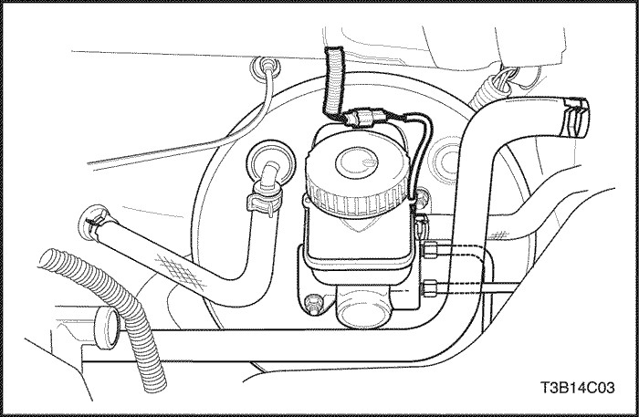
Vacuum Hose
Removal Procedure
- For vehicles with a DOHC engine, remove the clip on
the vacuum hose connection at the intake manifold.
- Pull the hose from the union nut connection. If the
hose does not remove easily or is deteriorated, pry off
and discard the hose.
- For vehicles with a SOHC engine, similarly remove
the clip on the vacuum hose nut connection to the intake
manifold.
- Pull the hose from the union nut connection. If the hose can not be removed easily or is deteriorated, pry off and discard the hose.
- Remove the clip on the vacuum hose connection to
the brake booster.
- Remove the vacuum hose.
Installation Procedure
- Mount the vacuum hose (DOHC engine connection
shown), and make sure the connections are tight on
each end.
- Install the vacuum hose clips.
- Check the function of the booster. Refer to the "Power Booster Functional Check"
in this section.
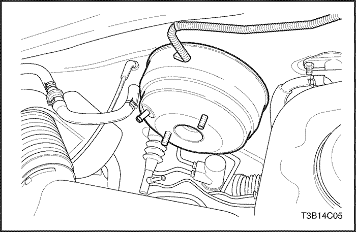
Power Booster Assembly
Removal Procedure
- Disconnect the electrical connector from the reservoir.
- For vehicles with a manual transaxle, disconnect the
clip on the clutch hose connection to the master cylinder.
- Plug the clutch hose and the master cylinder so that
the fluid does not escape.
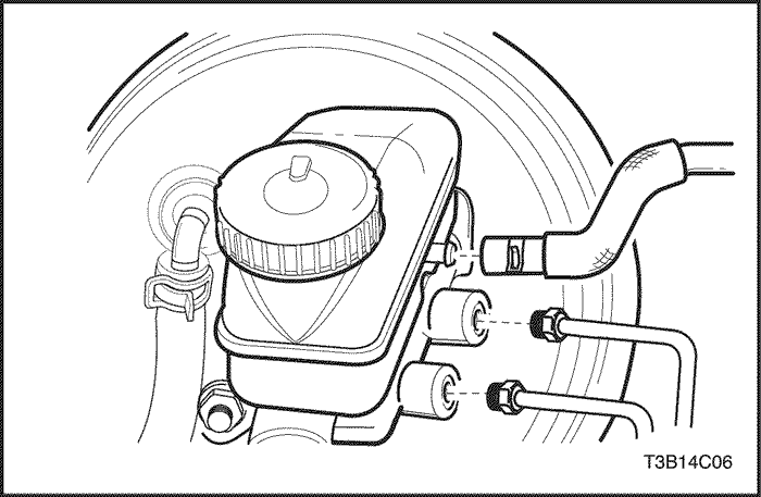
- Remove the master cylinder attaching nuts.
- Push the master cylinder forward slightly and move
it out of the way.
- Remove and discard the booster housing seal.
- Remove the clip on the vacuum hose connection to
the booster (DOHC engine connection shown).
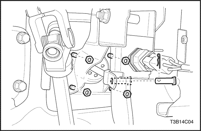
- Disconnect the brake lamp switch.
- Remove the brake pedal spring.
- Disconnect the clip and the pushrod pin from the
pedal bracket assembly. Refer to Section 4A, Hydraulic Brakes.
- Remove the booster and the support bracket-todash
panel nuts.
- Remove the booster and the bracket assembly from
the dash panel.
- Remove the bracket nuts from the booster and remove
the booster.
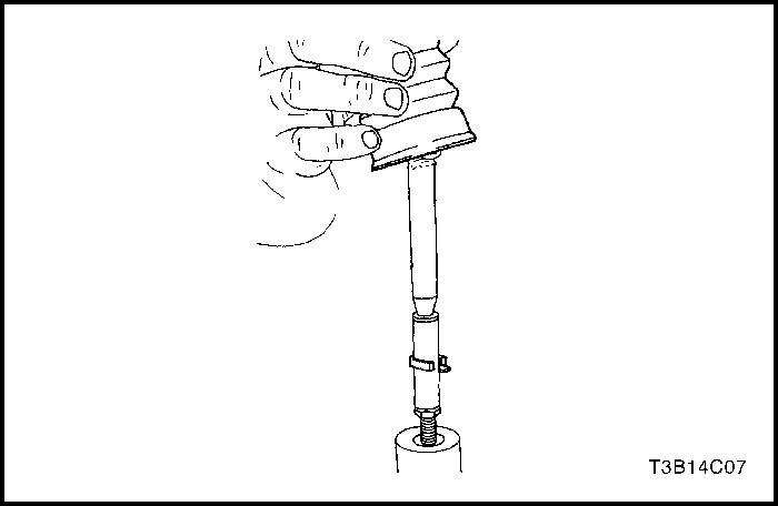
- Remove the rubber boot and the retainer.
- Remove the pushrod.
- Remove the adjustment sleeve from the pushrod.
- Remove the hex nut.
Installation Procedure
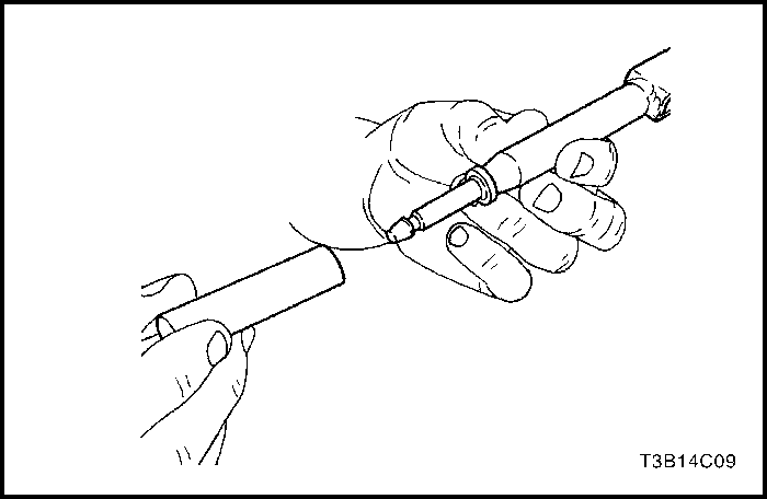
- Check the pushrod and the adjustment sleeve for
damage and proper fit.
- Install the hex nut and the adjustment sleeve on the
booster.
Tighten
Tighten the booster pushrod hex nut and the adjustment
sleeve to 16 N•m (12 lb-ft).
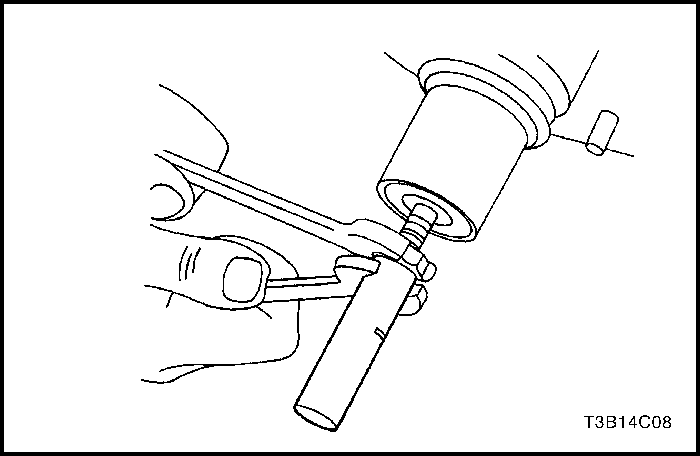
- Insert the pushrod in the adjustment sleeve and
mount the retainer.
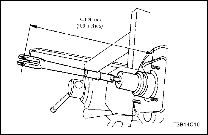
- Measure the distance from the booster to the center
of the fork bin bore.
- Install the rubber boot on the booster.
- Install the brackets to the booster.
Tighten
Tighten the booster-to-support bracket nuts to
12 N•m (9 lb-ft).
- Install the booster and the bracket assembly to the
dash panel.
Tighten
Tighten the booster and support bracket-to-dash panel
nuts to 24 N•m (18 lb-ft).
- Connect the master cylinder to the booster and
install a new booster housing seal.
Tighten
Tighten the master cylinder attaching nuts to 18 N•m
(13 lb-ft).
- Install the new vacuum hose to the booster (DOHC
engine connection shown). Refer to “Vacuum Hose”
in this section.
- Install new hose clamps on the vacuum hose.
- Install the pushrod pin to the brake pedal bracket assembly
and connect the clip and the spring. Refer to Section 4A, Hydraulic Brakes.
- Install the brake lamp switch.
GENERAL DESCRIPTION
AND SYSTEM OPERATION
Power Booster
This booster is a single diaphragm, vacuum-suspended
unit. In a normal operating mode, with the service brakes
in the release position, a vacuum-suspended booster
operates with a vacuum on both sides of its diaphragm.
When the brakes are applied, air at atmospheric pressure
is admitted to one side of the diaphragm to provide
the power assist. When the brakes are released, atmospheric
air is shut off from that side of the diaphragm.
The air is then drawn from the booster through the vacuumcheck
valve by the vacuumsource.
Important : If any hydraulic component is removed or
disconnected, it may be necessary to bleed all or part of
the brake system.


