GENERAL DESCRIPTION AND SYSTEM OPERATION
Basic Knowledge Required
Before using this section, it is important that you have a basic knowledge of the following items. Without this knowledge, it will be difficult to use the diagnostic procedures contained in this section.
- Basic Electrical Circuits : You should understand the basic theory of electricity and know the meaning of voltage, current (amps), and resistance (ohms). You should understand what happens in a circuit with an open or shorted wire. You should be able to read and understand a wiring diagram.
- Use of Circuit Testing Tools : You should know how to use a test light and how to bypass components to test circuits using fused jumper wires. You should be familiar with a digital multimeter. You should be able to measure voltage, resistance, and current, and be familiar with the controls and how to use them correctly.
ABS System Components
The Antilock Braking System (ABS) consists of a conventional hydraulic brake system plus antilock components. The conventional brake system includes a vacuum booster, master cylinder, front disc brakes, rear leading/trailing drum brakes, interconnecting hydraulic brake pipes and hoses, brake fluid level sensor and the BRAKE indicator.
The ABS components include a hydraulic unit, an electronic brake control module (EBCM), two system fuses, four wheel speed sensors (one at each wheel), interconnecting wiring, the ABS indicator, the EBD indicator (which is connected to the parking lamp) and the rear disk brakes. See ABS Component Locator" in this section for the general layout of this system.
The hydraulic unit with the attached EBCM is located between the surge tank and the fire wall on the left side of the vehicle.
The basic hydraulic unit configuration consists of hydraulic check valves, two solenoid valves for each wheel, a hydraulic pump, two accumulators, and two damper. The hydraulic unit controls hydraulic pressure to the front calipers and rear wheel cylinders by modulating hydraulic pressure to prevent wheel lockup.
Nothing in the hydraulic unit or the EBCM is serviceable. In the event of any failure, the entire ABS unit with attached EBCM must be replaced. For more information, refer to
"Base Braking Mode"
and
"Antilock Braking Mode"
in this section.
Base Braking Mode
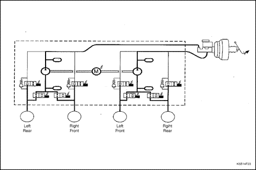
The baseline braking mode of the ABS system used in this vehicle is a diagonal split system. In this system, one master cylinder circuit supplies pressure to the right front and the left rear brakes; the other circuit supplies pressure to the left front and the right rear brakes. All valves in the hydraulic modulator are in their normal, non-energized positions as shown in the drawings found in "ABS System Components" in this section.
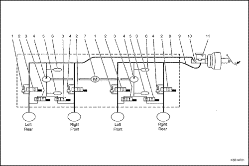


- Check Valve
- Inlet Valve
- Outlet Valve
- Pump
- Accumulator
- Damper
- Pump Motor
- Hydraulic Circuit 2
- Hydraulic Circuit 1
- Master Cylinder
- Master Cylinder Reservoir
Antilock Braking Mode - Apply
If a wheel speed sensor detects a wheel locking up, the electronic brake control module (EBCM) closes the normally open inlet valve for the brake on that wheel to prevent adding more hydraulic pressure to that brake.

Antilock Braking Mode - Hold
If the information from the wheel speed sensors indicate excessive wheel deceleration (imminent lockup), the first step in the antilock sequence is to isolate the brake pressure being applied by the driver. The EBCM sends a voltage to the coil to energize and close the inlet valves by pulling down on the armature. This prevents any additional fluid pressure applied by the driver from reaching the wheel. Though each channel of the 4-channel system can operate independently, once any front channel (brake) sees excessive deceleration, both front inlet valves are energized and close thus, with the inlet valves closed, further unnecessary increases in the brake pressure will be prohibited.
Antilock Braking Mode - Release
If the wheel locking tendency continues, the EBCM releases the hydraulic pressure at that brake by opening the outlet valve for that wheel.
EBD - Electronic Brake Force Distribution - System
As an add-on logic to the ABS base algorithm, EBD works in a range in which the intervention thresholds for ABS control are not reached yet.
EBD ensures that the rear wheels are sensitively monitored for slip with respect to the front axle. If slip is detected, the inlet valves for the rear wheels are switched to pressure hold to prevent a further increase in pressure at the rear-wheel breaks, thus electronically reproducing a pressure-reduction function at the rear-wheel brakes.

The Benefits of EBD
- Elimination of conventional proportioning valve.
- EBD utilizes the existing rear axle wheel speed sensor to monitor rear wheel slip.
- Based on many variables in algorithm a pressure hold, increase and/or decrease pulsetrain may be triggered at the rear wheels insuring vehicle stability.
- Vehicle approaches the ideal brake force distribution. (front to rear)
- Constant brake force distribution during vehicle lifetime.
- "Keep alive" function.
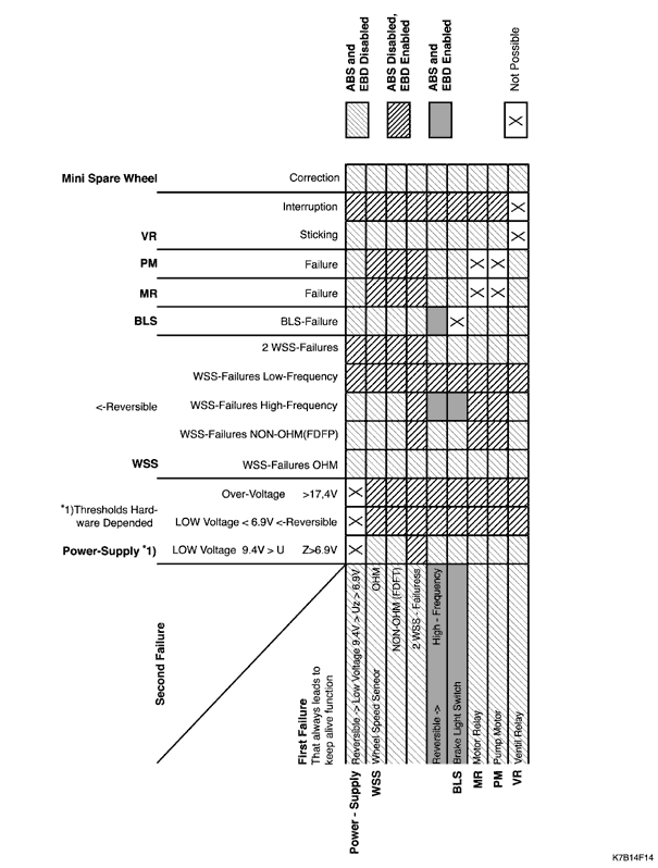
Electronic Brake-Force Distribution - EBD - Failure Matrix
HECU - Hydraulic Electronic Control Unit -
The HECU performs the following primary functions;
order to provide efficient braking and vehicle stability. In DDRP system, Power to the Rear Hold Valve Solenoid is provided from ignition. If the following fault conditions are existing, The Red Brake Warning Lamp will be illuminated.
- Monitor wheel speed sensor inputs.
- Detect wheel slip tendencies.
- Control the brake system while in the antilock control mode.
- Monitor the system for proper electrical operation.
The HECU continuously checks the speed of each wheel to determine if any wheel is beginning to slip. If any wheel slip tendency is detected, the HECU commands appropriate valve positions to modulate brake fluid pressure in some or all of the hydraulic circuits to prevent wheel slip and provide optimum braking. The HECU continues to control pressure in individual hydraulic circuits until a slipping tendency is no longer present. Also the HECU continuously monitors the ABS for proper operation. If the HECU detects an error, it can disable the ABS function and turn on the ABS Warning Lamp in the instrument cluster. The HECU also controls the display of the ABS DTCs (Diagnostic Trouble Codes) while in diagnostic mode.
Solenoid Relay
The solenoid relay, provides power to the pump motor and solenoids. The switch in the relay is normally open, but is commanded to close during initialization. The relay switch will remain closed for the remainder of the drive cycle as long as no DTCs (Diagnostic Trouble Codes) set which required the switch to open. If a DTC sets which requires the relay to be commanded off, battery voltage will be removed from the pump motor and solenoids for the remainder of the current drive cycle and ABS cannot function. The relay is an integral part of the HECU and cannot be serviced separately.
Wheel Speed Sensors
A wheel speed sensor is present at each wheel. The sensors transmit wheel speed information to the HECU by means of a small AC voltage. This voltage is generated by magnetic induction caused by passing a thoothed sensor ring past a stationary sensor. The magnitude and frequency of the AC voltage are proportional to the speed of the wheel and both will increase with increasing speed. The signal is transmitted to the HECU through interface that can cause false or noisy wheel speed sensor input to the HECU.
ABS Warning Lamp
The ABS warning lamp is located in the instrument cluster and will illuminate if a malfunction in the ABS is detected by the HECU. The ABS warning lamp informs the driver that a condition exists which results in turning off the antilock brake function. If only the ABS is warning lamp is on, normal braking with full power assist is available.
Conditions for the ABS warning lamp to turn on are as follows.
- ABS malfunction detected. As previously described, the ABS warning lamp turns on when a problem has been found in the ABS.
- Instrument panel cluster bulb check. When the ignition is turned to ON, the ABS warning lamp will turn on for approximately three seconds and then turn off.
Brake Warning Lamp
The red brake warning lamp in the in the instrument cluster and will illuminate to warn the driver of condition in the brake system, which may result in reduced braking ability. The lamp will illuminate when the parking brake is applied or not fully released, or if the brake fluid level switch is closed (when the brake fluid is low in the master cylinder reservoir). When the brake fluid level switch is closed (low condition) a brake warning lamp will stay illuminated until the condition has been repaired. Also some failure modes in ABS system will illuminate the lamp to let the drivers know DDRP (De-coupled Dynamic Rear Proportioning) is disabled
| © Copyright Chevrolet Europe. All rights reserved |