Aveo |
||||||||
|
||||||||
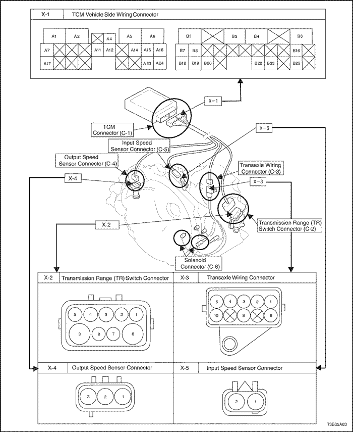
X-1 : TCM Vehicle Side Wiring Connector
|
|||||||
|
A1
|
Ground
|
B1
|
R
|
||||
|
A2
|
Pressure Control Solenoid Ground
|
B3
|
Clock
|
||||
|
A4
|
Pressure Control Solenoid
|
B4
|
Hold
|
||||
|
A5
|
Lock-Up Solenoid
|
B6
|
Input Speed Sensor
|
||||
|
A6
|
Ignition (+)
|
B7
|
D
|
||||
|
A7
|
CAN (Low)
|
B8
|
N
|
||||
|
A11
|
Transmission Fluid Temperature Sensor
|
B16
|
Input Speed Sensor Ground
|
||||
|
A12
|
Transmission Fluid Temperature Sensor Ground
|
B18
|
L
|
||||
|
A14
|
Timing Solenoid
|
B19
|
2
|
||||
|
A15
|
Shift Solenoid No.2
|
B20
|
P
|
||||
|
A16
|
Shift Solenoid No.1
|
B22
|
Stop Lamp Switch
|
||||
|
A17
|
CAN (High)
|
B23
|
DLC
|
||||
|
A23
|
Ground
|
B25
|
Output Speed Sensor
|
||||
|
A24
|
B+
|
-
|
-
|
||||
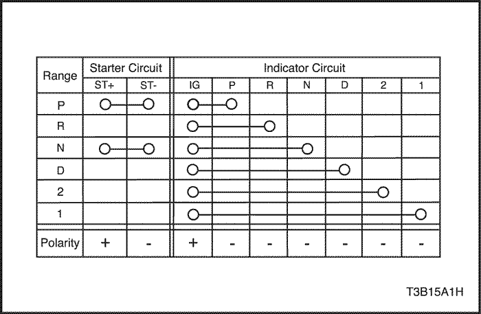
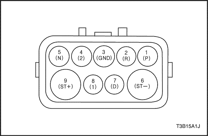
X-2 : TR Switch Connector
|
||||
|
1
|
P
|
|||
|
2
|
R
|
|||
|
3
|
Ground
|
|||
|
4
|
2
|
|||
|
5
|
N
|
|||
|
6
|
ST(-)
|
|||
|
7
|
D
|
|||
|
8
|
1
|
|||
|
9
|
ST(+)
|
|||
X-4 : Output Speed Sensor Connector
|
||||
|
1
|
Ignition
|
|||
|
2
|
Ground
|
|||
|
3
|
Output Speed Sensor
|
|||
X-3 : Transaxle Wiring Connector
|
||||
|
1
|
Transmission Fluid Temperature Sensor
|
|||
|
2
|
Timing Solenoid
|
|||
|
3
|
Pressure Control Solenoid
|
|||
|
4
|
Lock-Up Solenoid
|
|||
|
5
|
Shift Solenoid No.1
|
|||
|
6
|
Transmission Fluid Temperature Sensor Ground
|
|||
|
8
|
Pressure Control Solenoid Ground
|
|||
|
10
|
Shift Solenoid No.2
|
|||
X-5 : Input Speed Sensor
|
||||
|
1
|
Input Speed Sensor Ground
|
|||
|
2
|
Input Speed Sensor
|
|||
|
Standards
|
2390 ± 150 rpm
|
Result of Stall Test
|
Cause of Failure
|
|
Lower than standards
both "D" and "R"
|
Less engine power
Torque converter one way clutch failure
|
|
Higher than standards
only "D"
|
Lower line pressure
Forward clutch (C1) failure (Slipping)
No.2 One-way clutch (F2) failure
|
|
Higher than standards
only "R"
|
Lower line pressure
Reverse clutch (C3) failure (Slipping)
1st & reverse brake (B3) failure (Slipping)
|
|
Higher than standards
both "D" and "R"
|
Lower line pressure
Oil pump failure
Oil strainer failure (clogging)
Oil leak for each range circuit
|
|
"N → D"
|
less than 0.7 sec
|
|
"N" → "R"
|
less than 1.2 sec
|
Result of Time Lag Test
|
Cause of Failure
|
|
Longer than standards "N" → "D"
|
Lower line pressure
Forward Clutch (C1) failure (Slipping)
Timing solenoid failure
Oil leak for "D" range circuit
|
|
Longer than standards "N" → "R"
|
Lower line pressure
Reverse clutch (C3) failure (slipping)
1st & reverse brake (B3) failure (slipping)
Oil leak for "R" range circuit
|
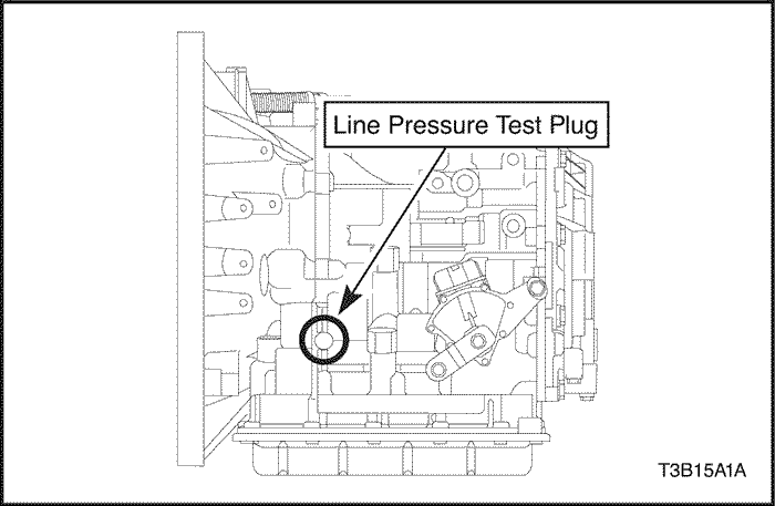
Line pressure Mpa (kgf/cm²)
|
D
|
R
|
|
Engine idle
|
0.37 (3.9)
-0.41 (4.2)
|
0.59 (6.0)
-0.68 (6.9)
|
|
Engine stall
|
1.10 (11.3)
-1.23 (12.5)
|
1.58 (16.2)
-1.83 (18.6)
|
Result of Hydraulic Test
|
Cause of Failure
|
|
Higher than standards
both "D and "R"
|
Pressure control solenoid (PCS) failure
Primary regulator valve failure
|
|
Lower than standards
both "D and "R"
|
Pressure control solenoid (PCS) failure
Primary regulator valve failure
Oil pump failure
Oil strainer failure (clogging)
Oil leak for each range circuit
|
|
Lower than standards
only "D
|
"D" hydraulic circuit failure
Forward clutch (C1) failure
|
|
Lower than standards
only "R"
|
"R" hydraulic circuit failure
Reverse clutch (C3) failure
1st and reverse brake (B3) failure
|
Range
|
Gear
|
|
D
|
3rd gear
|
|
R
|
Reverse
|
|
Standard Value
|
within 0.2mm (0.008 in)
|
|
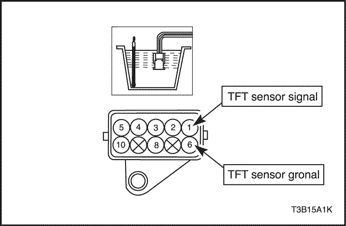
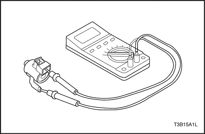
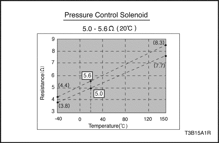
Standard Value
|
10°C
|
110°C
|
|
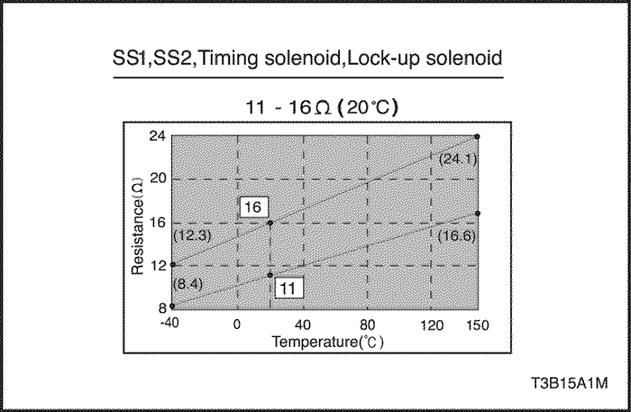
5.80~7.09 kΩ
|
0.23~0.263 kΩ
|
|
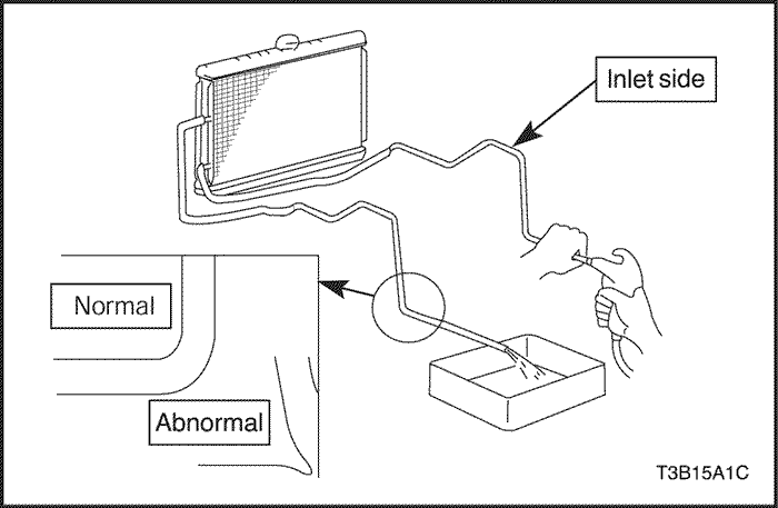
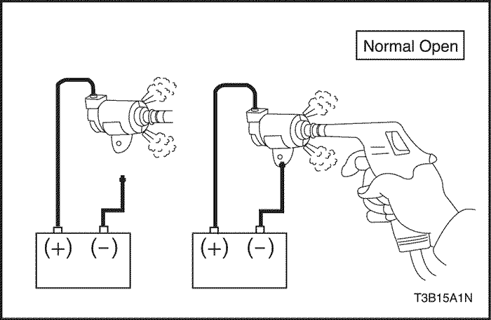
No battery connection
|
Leak air
|
|
Battery connection
|
No leak air
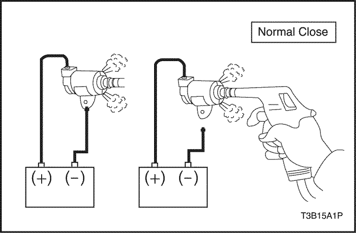
|
|
No battery connection
|
No leak air
|
|
Battery connection
|
Leak air
|

Step
|
Action
|
Yes
|
No
|
|
1
|
Does the shift lever move out of the PARK position?
|
Check for the intermittent and poor connections.
|
Go to Step 2
|
|
2
|
Does the shift lever move out of the PARK position?
|
Go to Step 4
|
Go to Step 3
|
|
3
|
Does the shift lever move out of the PARK position?
|
Go to Step 6
|
Go to Step 5
|
|
4
|
Do you find and correct the condition?
|
Go to Step 10
|
Go to Step 7
|
|
5
|
Inspect for poor connections at the BTSI solenoid.
Do you find and correct the condition?
|
Go to Step 10
|
Go to Step 8
|
|
6
|
Repair the short to battery in the BTSI solenoid supply circuit.
Is the repair complete?
|
Go to Step 10
|
-
|
|
7
|
Replace the brake switch. Refer to Section 4A, Hydraulic Brakes.
Is the replacement complete?
|
Go to Step 10
|
-
|
|
8
|
Replace the BTSI solenoid.
Is the problem found?
|
Go to Step 9
|
Go to Step 10
|
|
9
|
Replace the IP fuse or relay.
Is the replacement complete?
|
Go to Step 10
|
-
|
|
10
|
Operate the system in order to verify the repair.
Do you find and correct the condition?
|
System OK
|
Go to Step 1
|
Step
|
Action
|
Yes
|
No
|
|
1
|
Does the shift lever move out of the PARK position without pressing the brake?
|
Go to Step 2
|
Check for the intermittent and poor connections.
|
|
2
|
Does the test lamp illuminate?
|
Go to Step 3
|
Go to Step 7
|
|
3
|
Check for the wiring harness circuit between the brake switch terminal 1 and a good ground with a test lamp.
Does the test lamp illuminate?
|
Go to Step 8
|
Go to Step 4
|
|
4
|
Connect a test lamp between the ignition 1 voltage supply circuit at the BTSI solenoid and a good ground.
Does the test lamp illuminate?
|
Go to Step 5
|
Go to Step 9
|
|
5
|
Check for the wiring harness circuit between the BTSI solenoid terminal 3 and a good ground with a test lamp.
Does the test lamp illuminate?
|
Go to Step 6
|
Go to Step 10
|
|
6
|
Check for the wiring harness circuit between the P position switch terminal 1 and a good ground with a test lamp.
Does the test lamp illuminate?
|
Go to Step 15
|
Go to Step 11
|
|
7
|
Repair the open in the battery positive voltage supply circuit of the brake switch.
Is the repair complete?
|
Go to Step 16
|
-
|
|
8
|
Check for poor connections at the brake switch.
Do you find and correct the condition?
|
Go to Step 16
|
Go to Step 12
|
|
9
|
Repair the open in the ignition 1 voltage supply circuit of the BTSI solenoid.
Is the repair complete?
|
Go to Step 16
|
-
|
|
10
|
Check for poor connections at the BTSI solenoid.
Do you find and correct the condition?
|
Go to Step 16
|
Go to Step 13
|
|
11
|
Check for poor connections at the P position switch.
Do you find and correct the condition?
|
Go to Step 16
|
Go to Step 14
|
|
12
|
Replace the brake switch.
Is the repair complete?
|
Go to Step 16
|
-
|
|
13
|
Replace the BTSI solenoid.
Is the repair complete?
|
Go to Step 16
|
-
|
|
14
|
Replace the P position switch.
Is the repair complete?
|
Go to Step 16
|
-
|
|
15
|
Replace the IP fuse or relay.
Is the replacement complete?
|
Go to Step 16
|
-
|
|
16
|
Operate the system in order to verify the repair.
Do you find and correct the condition?
|
System OK
|
Go to Step 1
|
| © Copyright Chevrolet Europe. All rights reserved |


