Aveo |
||||||||
|
||||||||
DTC
|
DESCRIPTION
|
TYPE
|
Illuminate MIL
|
Blink
Hold Lamp
|
|
P0562
|
System Voltage Low
|
B
|
Yes
|
No
|
|
P0563
|
System Voltage High
|
B
|
Yes
|
No
|
|
P0601
|
Internal Control Module Memory Checksum Error
|
A
|
Yes
|
No
|
|
P0604
|
Internal Control Module Random Access Memory (RAM) Error
|
B
|
Yes
|
No
|
|
P0705
|
Transmission Range (TR) Switch Circuit Malfunction (No Signal)
|
B
|
Yes
|
No
|
|
P0706
|
Transmission Range (TR) Switch Circuit Malfunction (Short)
|
B
|
Yes
|
No
|
|
P0711
|
Transmission Fluid Temperature(TFT) Sensor Circuit Performance
|
A
|
Yes
|
No
|
|
P0712
|
Transmission Fluid Temperature Sensor Circuit Low Input
|
A
|
Yes
|
No
|
|
P0713
|
Transmission Fluid Temperature Sensor Circuit High Input
|
A
|
Yes
|
No
|
|
P0717
|
Input Shaft Speed (ISS) Sensor Circuit No Signal
|
A
|
Yes
|
No
|
|
P0722
|
Output Shaft Speed (OSS) sensor Circuit No Signal
|
A
|
Yes
|
No
|
|
P0741
|
Torque Converter Clutch (TCC) Circuit Performance or Stuck ON
|
B
|
Yes
|
No
|
|
P0742
|
Torque Converter Clutch (TCC) Circuit Stuck ON
|
B
|
Yes
|
No
|
|
P0751
|
Shift Solenoid 1 (SS1) Performance or Stuck OFF
|
B
|
Yes
|
No
|
|
P0752
|
Shift Solenoid 1 (SS1) Performance or Stuck ON
|
B
|
Yes
|
No
|
|
P0756
|
Shift Solenoid 2 (SS2) Performance or Stuck OFF
|
B
|
Yes
|
No
|
|
P0757
|
Shift Solenoid 2 (SS2) Performance or Stuck ON
|
B
|
Yes
|
No
|
|
P0787
|
Timing Solenoid (ST) Electrical (Ground Short)
|
A
|
Yes
|
No
|
|
P0788
|
Timing Solenoid (ST) Electrical (Open or Power Short)
|
A
|
Yes
|
No
|
|
P0962
|
Pressure Control Solenoid (PCS) Electrical (Low)
|
A
|
Yes
|
No
|
|
P0963
|
Pressure Control Solenoid (PCS) Electrical (High)
|
A
|
Yes
|
No
|
|
P0973
|
Shift Solenoid 1 (SS1) Electrical (Ground Short)
|
A
|
Yes
|
No
|
|
P0974
|
Shift Solenoid 1 (SS1) Electrical (Open or Power Short)
|
A
|
Yes
|
No
|
|
P0976
|
Shift Solenoid 2 (SS2) Electrical (Ground Short)
|
A
|
Yes
|
No
|
|
P0977
|
Shift Solenoid 2 (SS2) Electrical (Open or Power Short)
|
A
|
Yes
|
No
|
|
P2769
|
Torque Converter Clutch (TCC) Electrical (Ground Short)
|
B
|
Yes
|
No
|
|
P2770
|
Torque Converter Clutch (TCC) Electrical (Open or Power Short)
|
B
|
Yes
|
No
|
|
U0001
|
High Speed CAN Communication Bus
|
A
|
Yes
|
No
|
|
U0100
|
Lost Communication with ECM/PCM
|
A
|
Yes
|
No
|
|
U0401
|
Invalid Data Received from ECM/PCM
|
C1
|
No
|
Yes
|
| Step | Action | Value(s) | Yes | No |
| 1 |
Is the voltage within the values shown?
|
9-16v
|
Go to Step 4
|
Go to Step 2
|
| 2 |
Is the voltage within the values shown?
|
9-16v
|
Go to Step 4
|
Go to Step 3
|
| 3 |
Is the replacement completed?
|
-
|
System OK
|
-
|
| 4 |
Is the voltage within the values shown?
|
9-16v
|
Go to Step 6
|
Go to Step 5
|
| 5 |
Is the action completed?
|
-
|
System OK
|
-
|
| 6 |
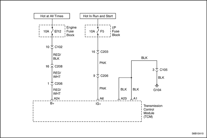
Inspect the Ef12,F5 fuse for an open.
Was a problem found?
|
-
|
Go to Step 7
|
Go to Step 8
|
| 7 |
Inspect the Ef12,F5 fuse for short. Replace the fuse if necessary.
Is the replacement complete?
|
-
|
System OK
|
-
|
| 8 |
Is the voltage within the values shown?
|
9-16v
|
Go to Step 10
|
Go to Step 9
|
| 9 |
Repair the fuse voltage supply lines for open.
Is the action completed?
|
-
|
System OK
|
-
|
| 10 |
Is the resistance within the values shown?
|
0Ω
|
Go to Step 12
|
Go to Step 11
|
| 11 |
Repair the circuit (between Ef12 and terminal A24) for short to ground and open.
Is the repair completed?
|
-
|
System OK
|
-
|
| 12 |
Is the voltage within the values shown?
|
9-16v
|
Go to Step 13
|
Go to Step 14
|
| 13 |
Repair the circuit from Ef12 to terminal A24 of the TCM for short to battery.
Is the repair completed?
|
-
|
System OK
|
-
|
| 14 |
Is the resistance within the values shown?
|
0Ω
|
Go to Step 17
|
Go to Step 15
|
| 15 |
Repair the circuit (between F5 and terminal A6) for short to ground and open.
Is the repair completed?
|
-
|
System OK
|
-
|
| 16 |
Is the voltage within the values shown?
|
9-16v
|
Go to Step 17
|
Go to Step 18
|
| 17 |
Repair the circuit (between F5 and terminal A6) for short to battery.
Is the repair completed?
|
-
|
System OK
|
-
|
| 18 |
Was a condition found?
|
-
|
Verify repair and Go to Step 20
|
Go to Step 19
|
| 19 |
Replace the TCM.
Note : Perform the transmission adaptive learn procedure. Refer to "Transmission Adaptive Learn Procedure"
in this section.
Is the replacement complete?
|
-
|
Go to Step 20
|
-
|
| 20 |
Has the last test failed or is the current DTC displayed?
|
-
|
Begin diagnosis again
|
Repair verified Exit DTC chart
|
| Step | Action | Value(s) | Yes | No |
| 1 |
Is the voltage within the values shown?
|
9-16v
|
Go to Step 4
|
Go to Step 2
|
| 2 |
Is the voltage within the values shown?
|
9-16v
|
Go to Step 4
|
Go to Step 3
|
| 3 |
Is the replacement completed?
|
-
|
System OK
|
-
|
| 4 |
Is the voltage within the values shown?
|
9-16v
|
Go to Step 6
|
Go to Step 5
|
| 5 |
Is the action completed?
|
-
|
System OK
|
-
|
| 6 |
Inspect the Ef12,F5 fuse for an open.
Was a problem found?
|
-
|
Go to Step 7
|
Go to Step 8
|
| 7 |
Inspect the Ef12,F5 fuse for short. Replace the fuse if necessary.
Is the replacement complete?
|
-
|
System OK
|
-
|
| 8 |
Is the voltage within the values shown?
|
9-16v
|
Go to Step 10
|
Go to Step 9
|
| 9 |
Repair the fuse voltage supply lines for open.
Is the action completed?
|
-
|
System OK
|
-
|
| 10 |
Is the resistance within the values shown?
|
0Ω
|
Go to Step 12
|
Go to Step 11
|
| 11 |
Repair the circuit (between Ef12 and terminal A24) for short to ground and open.
Is the repair completed?
|
-
|
System OK
|
-
|
| 12 |
Is the voltage within the values shown?
|
9-16v
|
Go to Step 13
|
Go to Step 14
|
| 13 |
Repair the circuit from Ef12 to terminal A24 of the TCM for short to battery.
Is the repair completed?
|
-
|
System OK
|
-
|
| 14 |
Is the resistance within the values shown?
|
0Ω
|
Go to Step 17
|
Go to Step 15
|
| 15 |
Repair the circuit (between F5 and terminal A6) for short to ground and open.
Is the repair completed?
|
-
|
System OK
|
-
|
| 16 |
Is the voltage within the values shown?
|
9-16v
|
Go to Step 17
|
Go to Step 18
|
| 17 |
Repair the circuit (between F5 and terminal A6) for short to battery.
Is the repair completed?
|
-
|
System OK
|
-
|
| 18 |
Was a condition found?
|
-
|
Verify repair and Go to Step 20
|
Go to Step 19
|
| 19 |
Replace the TCM.
Note : Perform the transmission adaptive learn procedure. Refer to "Transmission Adaptive Learn Procedure"
in this section.
Is the replacement completed?
|
-
|
Go to Step 20
|
-
|
| 20 |
Has the last test failed or is the current DTC displayed?
|
-
|
Begin diagnosis again
|
Repair verified Exit DTC chart
|
| Step | Action | Value(s) | Yes | No |
| 1 |
Is the Hold/Malfunction Indicator Lamp (MIL) ON?
|
-
|
Go to Step 2
|
Inspect Transmission Control Module (TCM) wiring harness and connector for signs of an intermittent condition. Repair as necessary.
|
| 2 |
Is DTC P0601 displayed?
|
-
|
Go to Step 3
|
Reprogram the TCM and perform the transmission adaptive learn procedure. Refer to "Transmission Adaptive Learn Procedure"
in this section.
|
| 3 |
Replace the TCM.
Is the replacement completed?
|
-
|
Perform the transmission adaptive learn procedure. Refer to "Transmission Adaptive Learn Procedure"
in this section.
|
-
|
| Step | Action | Value(s) | Yes | No |
| 1 |
Is the Hold/Malfunction Indicator Lamp (MIL) ON?
|
-
|
Go to Step 2
|
Inspect Transmission Control Module (TCM) wiring harness and connector for signs of an intermittent condition. Repair as necessary.
|
| 2 |
Is DTC P0604 displayed?
|
-
|
Go to Step 3
|
Reprogram the TCM and perform the transmission adaptive learn procedure. Refer to "Transmission Adaptive Learn Procedure"
in this section.
|
| 3 |
Replace the TCM.
Is the replacement completed?
|
-
|
Perform the transmission adaptive learn procedure. Refer to "Transmission Adaptive Learn Procedure"
in this section.
|
-
|
Terminal
|
Condition
|
Resistance
|
|
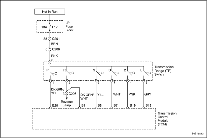
B20-A23, A1
|
"P" position
|
less than 1Ω
|
|
Not "P" position
|
more than 10kΩ
|
|
|
B1-A23, A1
|
"R" position
|
less than 1Ω
|
|
Not "R" position
|
more than 10kΩ
|
|
|
B8-A23, A1
|
"N" position
|
less than 1Ω
|
|
Not "N" position
|
more than 10kΩ
|
|
|
B7-A23, A1
|
"D" position
|
less than 1Ω
|
|
Not "D" position
|
more than 10kΩ
|
|
|
B19-A23,A1
|
"2" position
|
less than 1Ω
|
|
Not "2" position
|
more than 10kΩ
|
|
|
B18-A23,A1
|
"1" position
|
less than 1Ω
|
|
Not "1" position
|
more than 10kΩ
|
| Step | Action | Value(s) | Yes | No |
| 1 |
Is the Hold/Malfunction Indicator Lamp (MIL) ON?
|
-
|
Go to Step 2
|
Inspect the temporary connection failure of the connector and repair it if necessary. Refer to "Wiring Harness and Connector Inspection" in this section.
|
| 2 |
Is DTC P0705 displayed?
|
-
|
Go to Step 3
|
Inspect the temporary connection failure of the connector and repair it if necessary. Refer to "Wiring Harness and Connector Inspection" in this section.
|
| 3 |
Is the inspection OK?
|
-
|
Go to Step 4
|
Go to Step 5
|
| 4 |
Is the inspection OK?
|
-
|
Clean the connectors.
|
Replace the vehicle harness or adjustment between the connectors.
|
| 5 |
Is the inspection OK?
|
-
|
Go to Step 4
|
Replace the TR switch.
|
Terminal
|
Condition
|
Resistance
|
|
B20-A23, A1
|
"P" position
|
less than 1Ω
|
|
Not "P" position
|
more than 10kΩ
|
|
|
B1-A23, A1
|
"R" position
|
less than 1Ω
|
|
Not "R" position
|
more than 10kΩ
|
|
|
B8-A23, A1
|
"N" position
|
less than 1Ω
|
|
Not "N" position
|
more than 10kΩ
|
|
|
B7-A23, A1
|
"D" position
|
less than 1Ω
|
|
Not "D" position
|
more than 10kΩ
|
|
|
B19-A23,A1
|
"2" position
|
less than 1Ω
|
|
Not "2" position
|
more than 10kΩ
|
|
|
B18-A23,A1
|
"1" position
|
less than 1Ω
|
|
Not "1" position
|
more than 10kΩ
|
| Step | Action | Value(s) | Yes | No |
| 1 |
Is the Hold/Malfunction Indicator Lamp (MIL) ON?
|
-
|
Go to Step 2
|
Inspect the temporary connection failure of the connector and repair it if necessary. Refer to "Wiring Harness and Connector Inspection" in this section.
|
| 2 |
Is DTC P0706 displayed?
|
-
|
Go to Step 3
|
Inspect the temporary connection failure of the connector and repair it if necessary. Refer to "Wiring Harness and Connector Inspection" in this section.
|
| 3 |
Is the inspection OK?
|
-
|
Go to Step 4
|
Go to Step 5
|
| 4 |
Is the inspection OK?
|
-
|
Clean the connectors.
|
Replace the vehicle harness or adjustment between the connectors.
|
| 5 |
Is the inspection OK?
|
-
|
Go to Step 4
|
Replace the TR switch.
|
| Step | Action | Value(s) | Yes | No |
| 1 |
Is the Hold/Malfunction Indicator Lamp (MIL) ON?
|
-
|
Go to Step 2
|
Inspect the temporary connection failure of the connector and repair it if necessary. Refer to "Wiring Harness and Connector Inspection" in this section.
|
| 2 |
Is DTC P0711 displayed?
|
-
|
Go to Step 3
|
Clean the connector.
|
| 3 |
Warm up the engine (coolant temperature:60°C (140°F) and check the following condition:
Does the transmission oil temperature rise with the rise of the engine coolant temperature?
|
-
|
Clean the connector.
|
Go to Step 4
|
| 4 |
Is the measurement within the specified value?
|
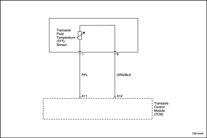
10 °C (50°F): 5.80-7.09 kΩ
110 °C (230°F): 0.231-0.263 kΩ
|
Go to Step 5
|
Replace the TFT sensor.
|
| 5 |
Is the condition OK?
|
-
|
Clean the connector.
|
Replace the vehicle harness or adjustment between the connectors.
|
| Step | Action | Value(s) | Yes | No |
| 1 |
Is the Hold/Malfunction Indicator Lamp (MIL) ON?
|
-
|
Go to Step 2
|
Inspect the temporary connection failure of the connector and repair it if necessary. Refer to "Wiring Harness and Connector Inspection" in this section.
|
| 2 |
Is DTC P0712 displayed?
|
-
|
Go to Step 3
|
Inspect the temporary connection failure of the connector and repair it if necessary. Refer to "Wiring Harness and Connector Inspection" in this section.
|
| 3 |
Is the measurement within the specified value?
|
10°C (50°F): 5.80-7.09 kΩ
110°C (230°F: 0.231-0.263 kΩ
|
Go to Step 4
|
Go to Step 5
|
| 4 |
Is the inspection OK?
|
-
|
Go to Step 6
|
Replace the vehicle harness or adjustment between the connectors.
|
| 5 |
Is the measurement within the specified value?
|
10°C (50°F): 5.80-7.09 kΩ
110°C (230°F): 0.231-0.263 kΩ
|
Go to Step 7
|
Replace the TFT sensor.
|
| 6 |
Clean the connector.
Is the failure resolved?
|
-
|
System OK
|
Go to Step 8
|
| 7 |
Is the condition OK?
|
-
|
Clean the connectors.
|
Replace the vehicle harness or adjustment between the connectors.
|
| 8 |
Replace the TCM.
Is the replacement completed?
|
-
|
Perform the transmission adaptive learn procedure. Refer to "Transmission Adaptive Learn Procedure"
in this section.
|
-
|
| Step | Action | Value(s) | Yes | No |
| 1 |
Is the Hold/Malfunction Indicator Lamp (MIL) ON?
|
-
|
Go to Step 2
|
Inspect the temporary connection failure of the connector and repair it if necessary. Refer to "Wiring Harness and Connector Inspection" in this section.
|
| 2 |
Is DTC P0713 displayed?
|
-
|
Go to Step 3
|
Inspect the temporary connection failure of the connector and repair it if necessary. Refer to "Wiring Harness and Connector Inspection" in this section.
|
| 3 |
Is the measurement within the specified value?
|
10°C (50°F): 5.80-7.09 kΩ
110°C (230°F: 0.231-0.263 kΩ
|
Go to Step 4
|
Go to Step 5
|
| 4 |
Is the inspection OK?
|
-
|
Go to Step 6
|
Replace the vehicle harness or adjustment between the connectors.
|
| 5 |
Is the measurement within the specified value?
|
10°C (50°F): 5.80-7.09 kΩ
110°C (230°F): 0.231-0.263 kΩ
|
Go to Step 7
|
Replace the TFT sensor.
|
| 6 |
Clean the connector.
Is the failure resolved?
|
-
|
System OK
|
Go to Step 8
|
| 7 |
Is the condition OK?
|
-
|
Clean the connectors.
|
Replace the vehicle harness or adjustment between the connectors.
|
| 8 |
Replace the TCM.
Is the replacement completed?
|
-
|
Perform the transmission adaptive learn procedure. Refer to "Transmission Adaptive Learn Procedure"
in this section.
|
-
|
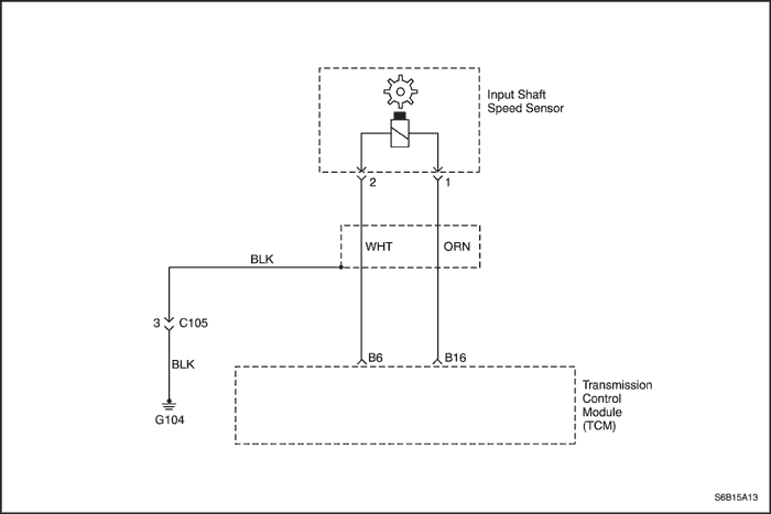
| Step | Action | Value(s) | Yes | No |
| 1 |
Is the Hold/Malfunction Indicator Lamp (MIL) ON?
|
-
|
Go to Step 2
|
Inspect the temporary connection failure of the connector and repair it if necessary. Refer to "Wiring Harness and Connector Inspection"
in this section.
|
| 2 |
Is DTC P0717 displayed?
|
-
|
Go to Step 3
|
Inspect the temporary connection failure of the connector and repair it if necessary. Refer to "Wiring Harness and Connector Inspection"
in this section.
|
| 3 |
Is the measurement within the specified value?
|
20°C (68°F): 560-680 Ω
|
Go to Step 4
|
Go to Step 5
|
| 4 |
Is the inspection OK?
|
-
|
Go to Step 6
|
Replace the vehicle harness or adjustment between the connectors.
|
| 5 |
Inspect the input shaft speed(ISS) sensor. Refer to "Unit Inspection"
in this section.
Is the inspection OK?
|
-
|
Go to Step 7
|
Replace the ISS sensor.
|
| 6 |
Clean the connector.
Is the failure resolved?
|
-
|
System OK
|
Go to Step 8
|
| 7 |
Is the condition OK?
|
-
|
Clean the connector.
|
Replace the vehicle harness or adjustment between the connectors.
|
| 8 |
Replace the TCM.
Is the replacement completed?
|
-
|
Perform the transmission adaptive learn procedure. Refer to "Transmission Adaptive Learn Procedure"
in this section.
|
-
|
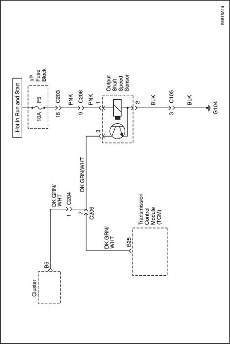
| Step | Action | Value(s) | Yes | No |
| 1 |
Is the Hold/Malfunction Indicator Lamp (MIL) ON?
|
-
|
Go to Step 2
|
Inspect the temporary connection failure of the connector and repair it if necessary. Refer to "Wiring Harness and Connector Inspection"
in this section.
|
| 2 |
Is DTC P0722 displayed?
|
-
|
Go to Step 3
|
Inspect the temporary connection failure of the connector and repair it if necessary. Refer to "Wiring Harness and Connector Inspection"
in this section.
|
| 3 |
Does the measurement change within the specified value?
|
0 – 12 v
|
Go to Step 4
|
Go to Step 5
|
| 4 |
Is the inspection OK?
|
-
|
Go to Step 6
|
Replace the vehicle harness or adjustment between the connectors.
|
| 5 |
Inspect the output shaft speed (OSS) sensor. Refer to "Unit Inspection"
in this section.
Is the inspection OK?
|
-
|
Go to Step 7
|
Replace the OSS sensor.
|
| 6 |
Clean the connector.
Is the failure resolved?
|
-
|
System OK
|
Go to Step 8
|
| 7 |
Is the condition OK?
|
-
|
Clean the connector.
|
Replace the vehicle harness or adjustment between the connectors.
|
| 8 |
Replace the TCM.
Is the replacement completed?
|
-
|
Perform the transmission adaptive learn procedure. Refer to "Transmission Adaptive Learn Procedure" in this section.
|
-
|
| © Copyright Chevrolet Europe. All rights reserved |


