- Remove the transaxle assembly from the vehicle. Refer to "Transaxle Assembly" in this section.
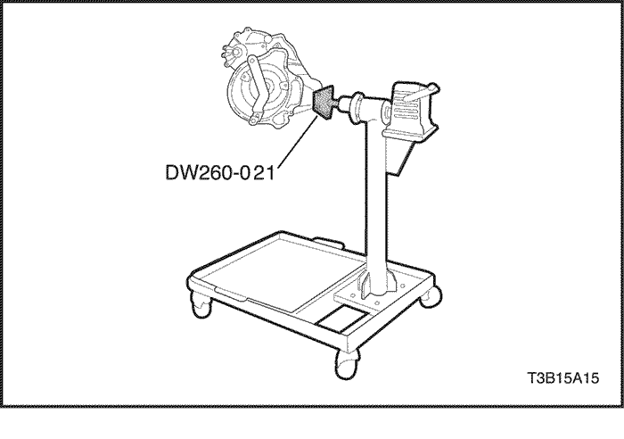
- Install the transaxle assembly to the transaxle support stand using Automatic Transaxle Overhaul Fixture DW260-021-02 (81-40 LE).
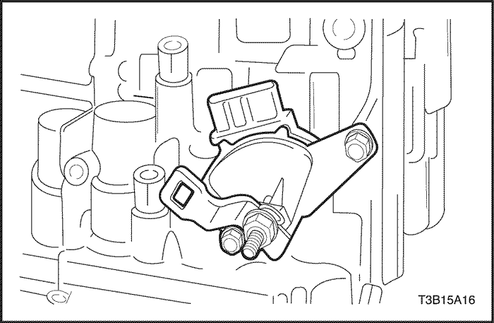


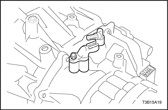
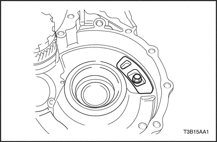
- Remove the nut, washer and control lever.
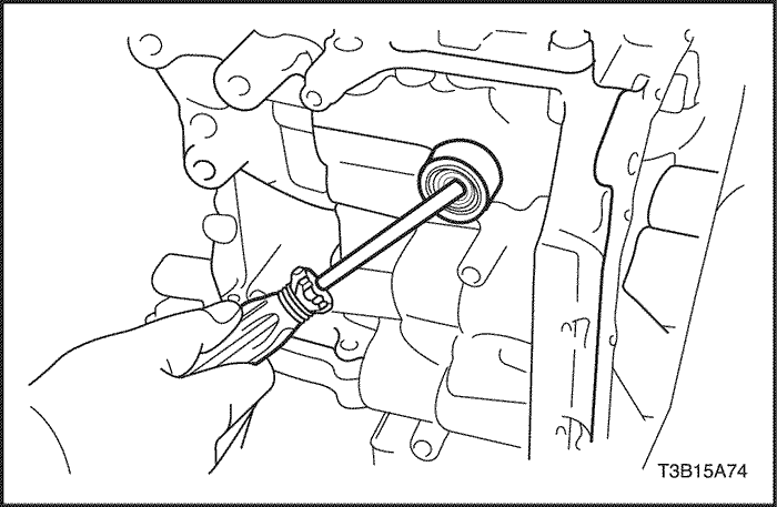
- Using a screwdriver, unstake the lock washer.
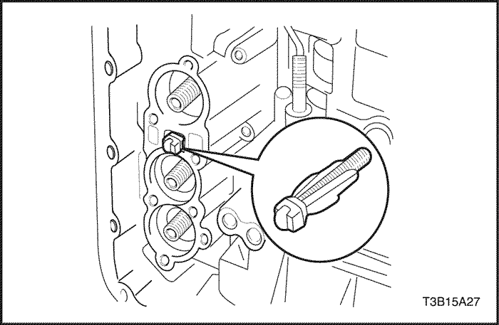
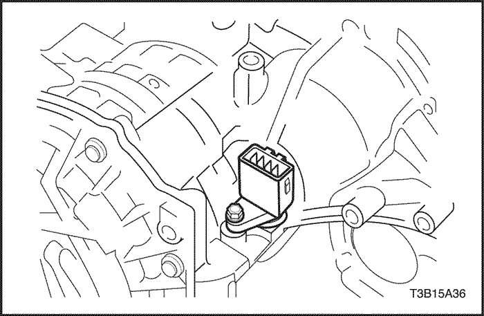
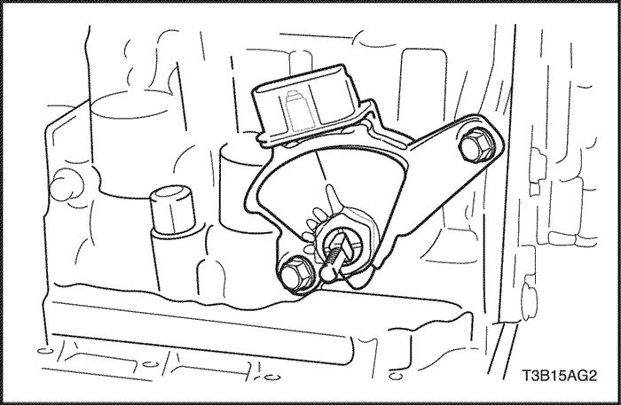
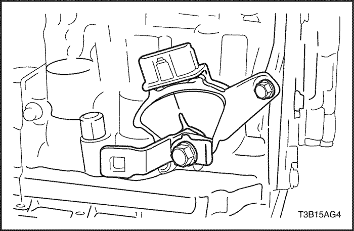
- Remove the two bolts and nut and pull out the TR switch.
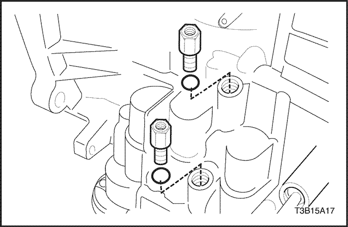
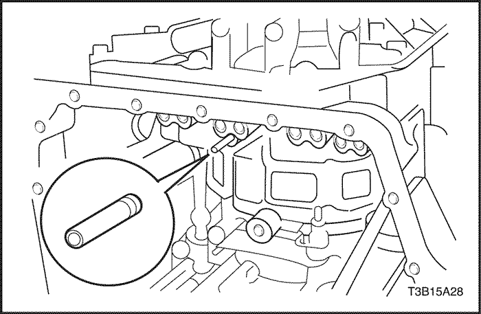
- Remove the two unions the transaxle case.
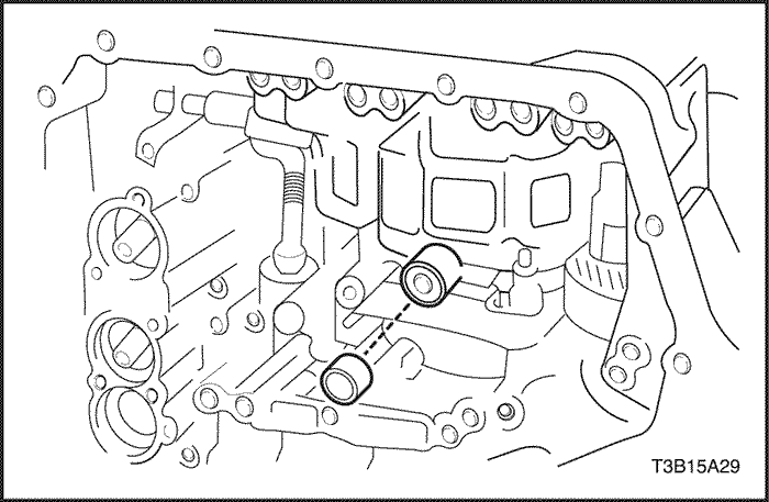
- Remove the two O-rings from the unions.
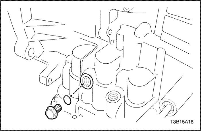
- Remove the screw plug from the transaxle case.
- Remove the O-ring from the screw plug.
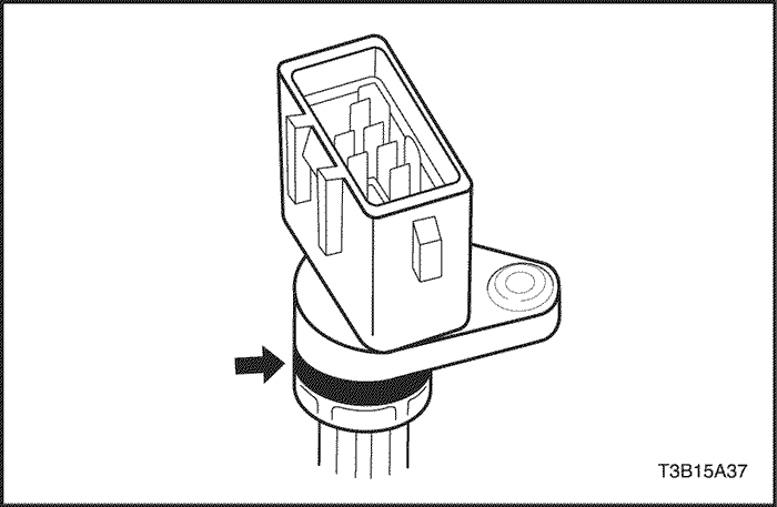
- Remove the bolt and the input shaft speed (ISS) sensor.
- Remove the breather plug.
- Remove the O-ring from the breather plug.
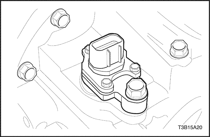
- Remove the bolt and the output shaft speed (OSS) sensor.
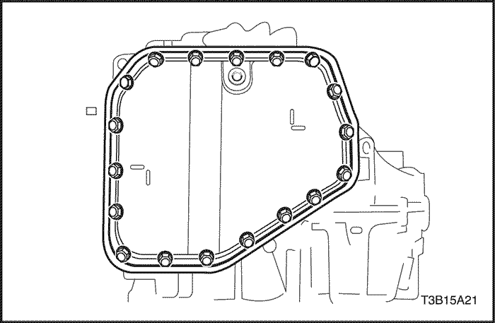
- Remove the 18 bolts.
- Remove the oil pan and gasket.
- Remove the drain plug from the oil pan.
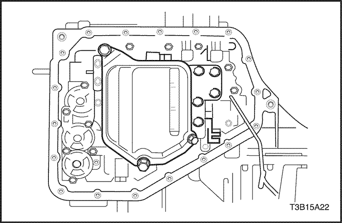
- Remove the three bolts and oil strainer.
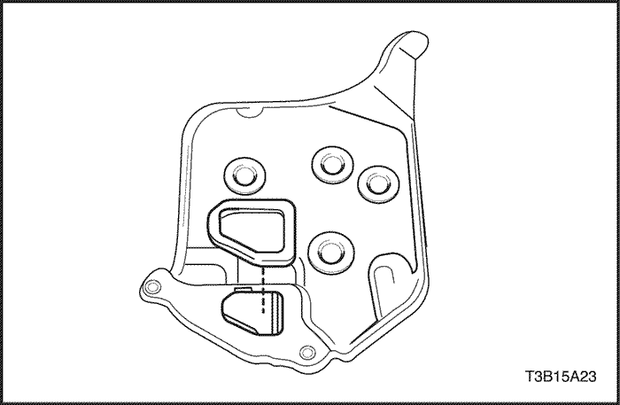
- Remove the gasket from the oil strainer.
- Remove the bolt and transmission fluid temperature sensor with the clamp.
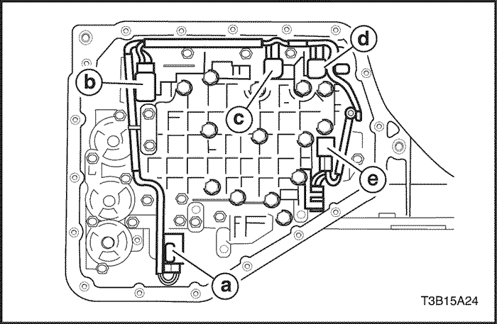
- Disconnect the 5 solenoid connectors.
-
- a. Lock-up control solenoid
- b. Pressure control solenoid.
- c. No.2 shift solenoid.
- d. No.1 shift solenoid.
- e. Timing solenoid
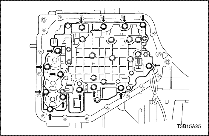
- Support the valve body assembly and remove the 14 bolts.
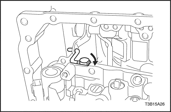
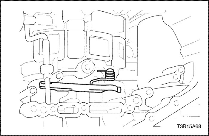
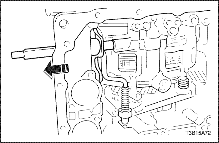
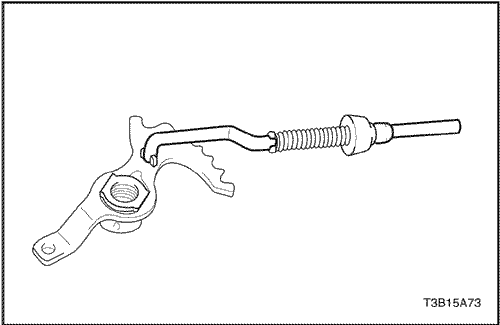
- Disconnect the manual valve control rod from the manual valve lever, then remove the valve body assembly.
- Remove the check valve and spring.
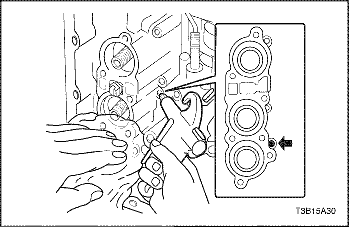
- Remove the brake drum gasket.
- Remove the apply gasket.
USE CAUTION WHEN REMOVING COMPONENTS WITH COMPRESSED AIR OR PERSONAL INJURY MAY RESULT.
Notice : Blowing off the air may cause the piston's jump-out.When removing the piston, hold it with your hand using a waste cloth.
Notice : Take care not to splash automatic transaxle fluid (ATF) when air-blowing.
- Apply 392 kPa (57 psi) of compressed air to the oil hole and remove the direct clutch (C2) accumulator piston and spring.
- Remove the spring.
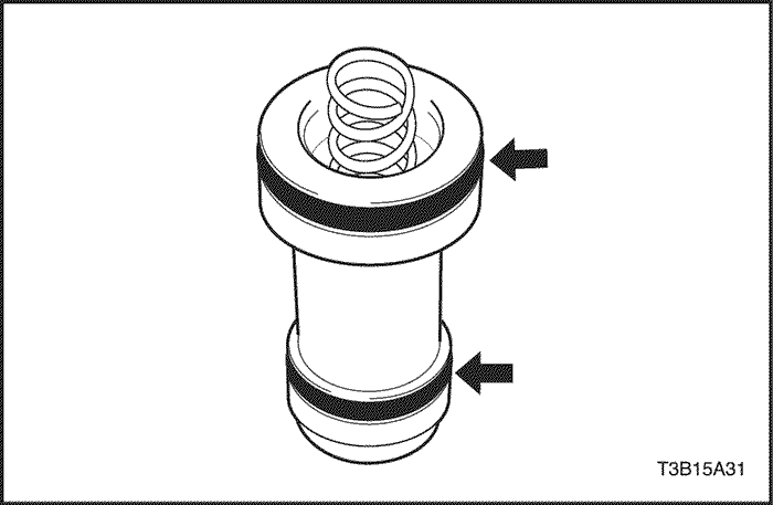
- Remove the 2 O-rings from the direct clutch (C2) accumulator piston.
USE CAUTION WHEN REMOVING COMPONENTS WITH COMPRESSED AIR OR PERSONAL INJURY MAY RESULT.
Notice : Blowing off the air may cause the piston's jump-out.When removing the piston, hold it with your hand using a waste cloth.
Notice : Take care not to splash ATF when air-blowing.
- Apply 392 kPa (57 psi) of compressed air to the oil hole and remove the forward clutch (C1) accumulator piston and spring.
- Remove the spring.

- Remove the 2 O-rings from the forward clutch (C1) accumulator piston.
USE CAUTION WHEN REMOVING COMPONENTS WITH COMPRESSED AIR OR PERSONAL INJURY MAY RESULT.
Notice : Blowing off the air may cause the piston's jump-out.When removing the piston, hold it with your hand using a waste cloth.
Notice : Take care not to splash ATF when air-blowing.
- Apply 392 kPa (57 psi) of compressed air to the oil hole and remove the O/D & 2nd brake (B1) clutch accumulator piston and spring.
- Remove the 2 O-rings from the O/D & 2nd brake (B1) accumulator piston.
- Remove the bolt and the transaxle wire from the transaxle case.
- Remove the O-ring from the transaxle wire.
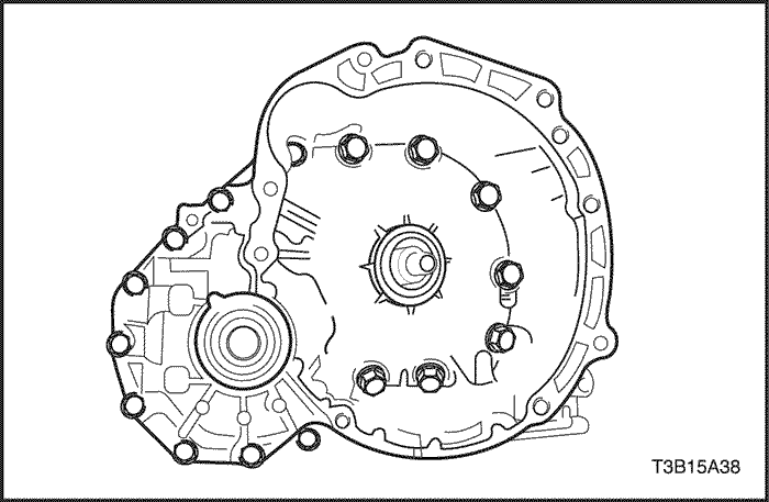
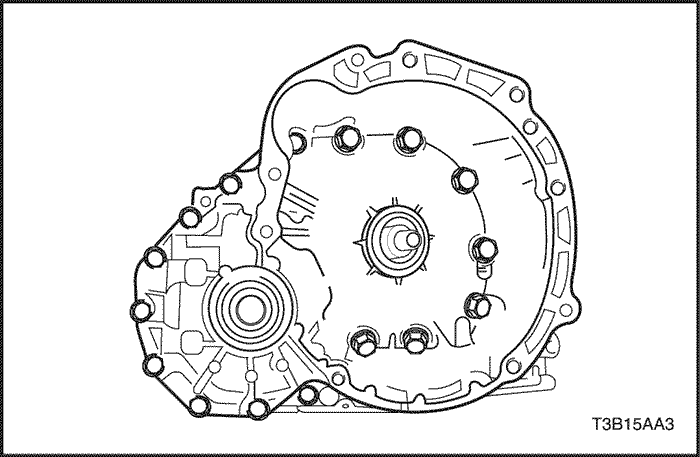
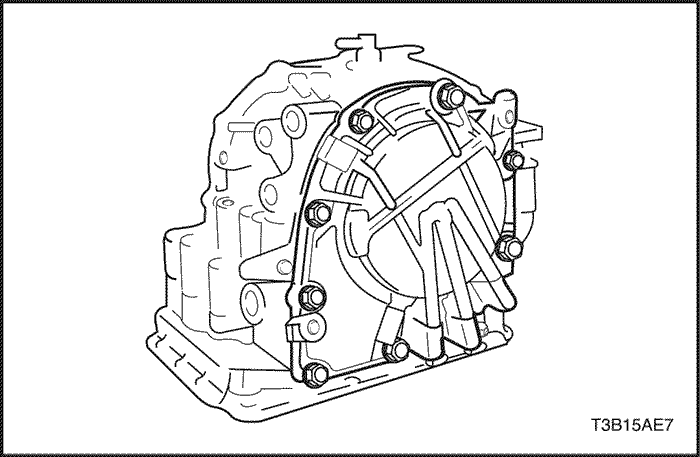
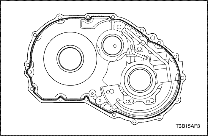
- Remove the 16 bolts and tap on the circumference of the transaxle housing with a plastic hammer to remove the transaxle housing from the transaxle case.
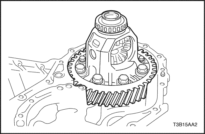
Important : Be careful not to drop the differential gear assembly when the transaxle housing is removed.
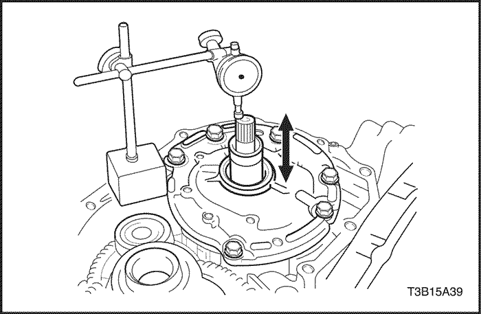
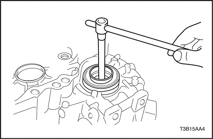
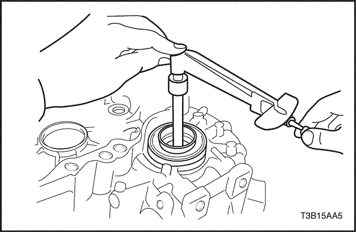
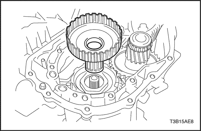
- Using a dial indicator, measure the input shaft end play.
- End play : 0.3 – 0.9 mm (0.012-0.035 in.)
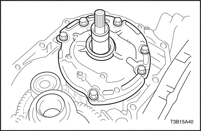
- Remove the 6 bolts and oil pump.
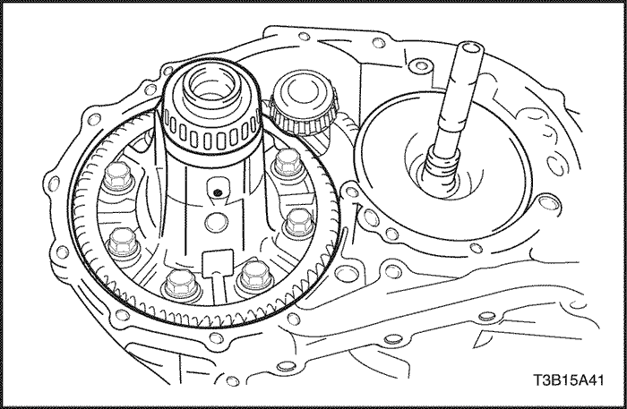
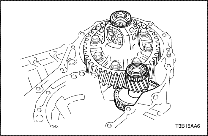
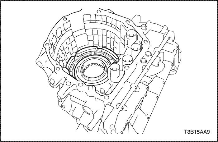
- Remove the differential gear assembly from the transaxle case.
- Remove the apply gasket.
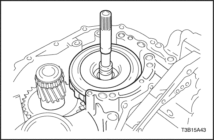
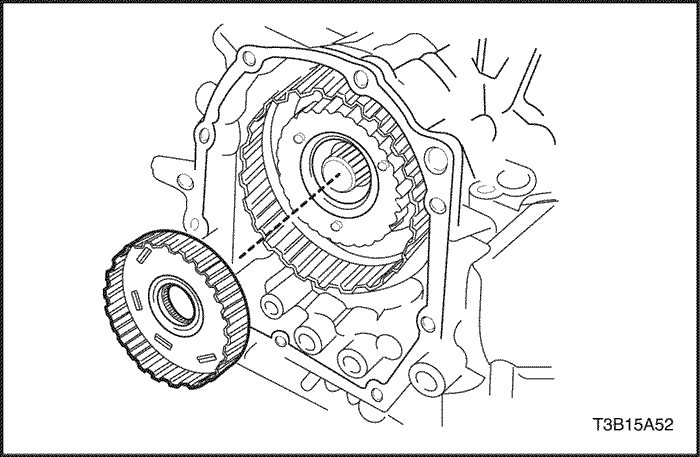
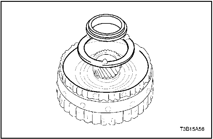
- Remove the direct clutch (C2) assembly from the transaxle case.
- Remove the thrust needle roller bearing from the direct clutch assembly.
- Remove the direct clutch (C2) hub, thrust needle roller bearing and thrust bearing race from the transaxle case.
- Remove the counter driven gear assembly from the transaxle case.
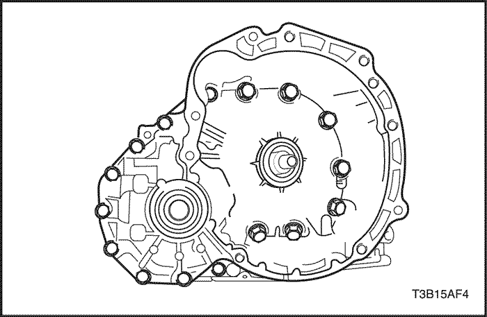
- Remove the 9 bolts and tap on the circumference of the transaxle rear cover with a plastic hammer to remove the transaxle rear cover from the transaxle case.
- Remove the 4 apply gaskets.
- Remove 2nd coast & O/D brake (B1) flanges, discs and a plate from the transaxle case.
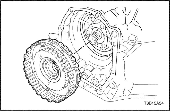
- Remove the thrust needle roller bearing and forward & reverse clutch assembly.
- Remove the thrust needle roller bearing and thrust bearing race from the forward & reverse clutch assembly.
- Remove the forward clutch hub from the transaxle case.
- Remove the thrust bearing race and thrust neddle roller bearing from the forward clutch hub.
- Remove rear planetary sun gear and one-way clutch assembly.
- Remove the thrust bearing race from the rear planetary sun gear and one-way clutch assembly.
- Remove the thrust needle roller bearing and planetary carrier thrust washer from the rear planetary sun gear and one-way clutch assembly.
- Remove the one-way clutch assembly and thrust washer from the rear planetary sun gear.
- Remove the front planetary sun gear from the transaxle case.
- Remove the thrust bearing race from the front planetary sun gear.
USE CAUTION WHEN REMOVING SNAP RINGS OR PERSONAL INJURY MAY RESULT.
Notice : Stop the press when the 2nd brake is lowered 1- 2 mm (0.039-0.078 in.) from the snap ring groove, preventing the 2nd brake from being deformed.
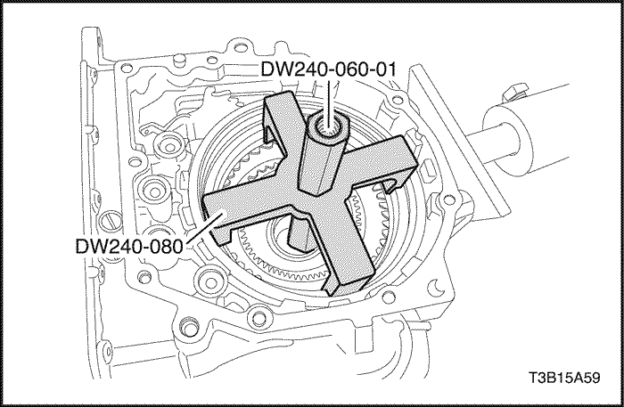
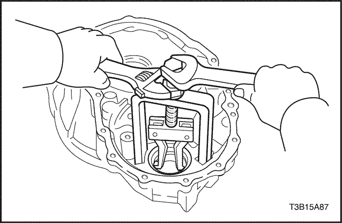
- Using brake spring compressor bolt/nut DW240-060-01 and 2nd brake adapter DW240-080, remove the 2 snap rings, 2nd brake piston and 2nd brake piston return spring.
USE CAUTION WHEN REMOVING COMPONENTS WITH COMPRESSED AIR OR PERSONAL INJURY MAY RESULT.
Notice : Blowing off the air may cause the piston's jump-out.When removing the piston, hold it with your hand using a waste cloth.
Notice : Take care not to splash ATF when air-blowing.
- Apply 392 kPa (57 psi) of compressed air to the 2nd brake to remove the 2nd brake piston from the 2nd brake clutch cylinder.
- Remove the 2 O-rings from the 2nd brake piston.
- Remove the 2 plates, 2 discs and flange.
- Remove the No. 2 one-way clutch and planetary gear from the transaxle case.
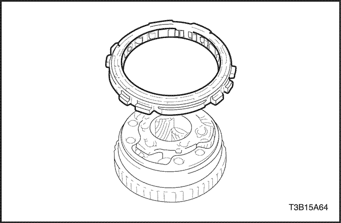
- Remove the No. 2 one-way clutch from the planetary gear and remove the anti-rattle clip.
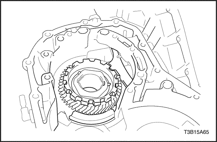
- Fix the counter drive gear with the parking lock pawl.
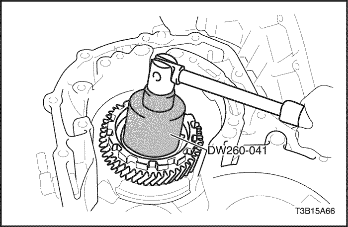
- Remove the planetary ring gear nut using planetary ring gear nut removal/installation socket DW 260-041.
Notice : Remove the nut without unstaking the planetary ring gear. If chisel or other tool is used to unstake the planetary ring gear, such impact may damage the bearing.
- Remove the 2 bolts and parking lock pawl bracket.
- Remove the parking lock pawl shaft, torsion spring and parking lock pawl.
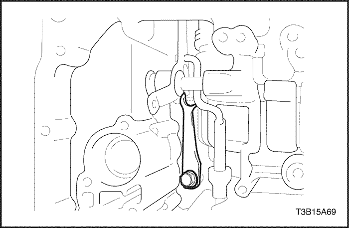
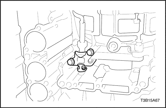
- Remove the bolt and manual detent spring.
- Using a chisel and hammer, unstake and remove the spacer.
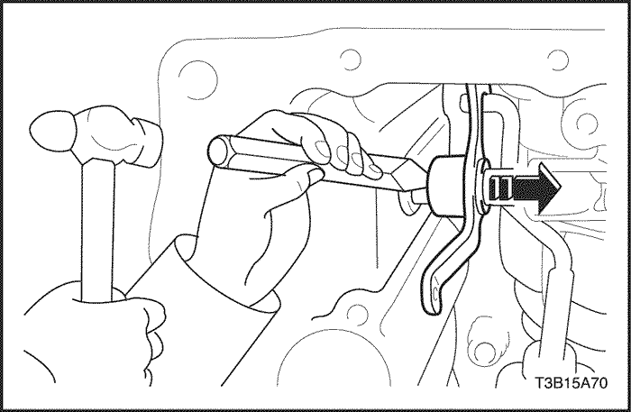
- Using a pin punch and hammer, drive out the pin.
- Remove the manual valve lever shaft and manual valve lever.
- Remove the parking lock rod from the manual valve lever.
- Using a screwdriver, remove the oil seal.
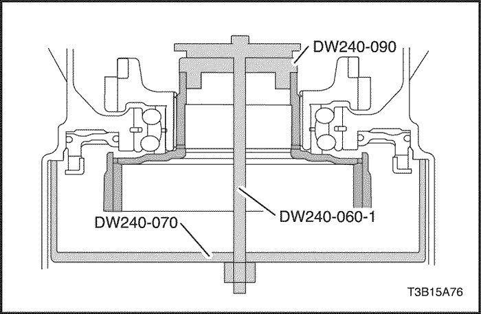
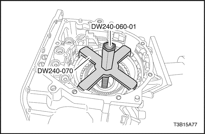
- Using brake spring compressor bolt/nut DW240-060-01, 1st & reverse brake adapter DW240-070 and planetary ring gear remover DW240-090, remove the planetary ring gear.
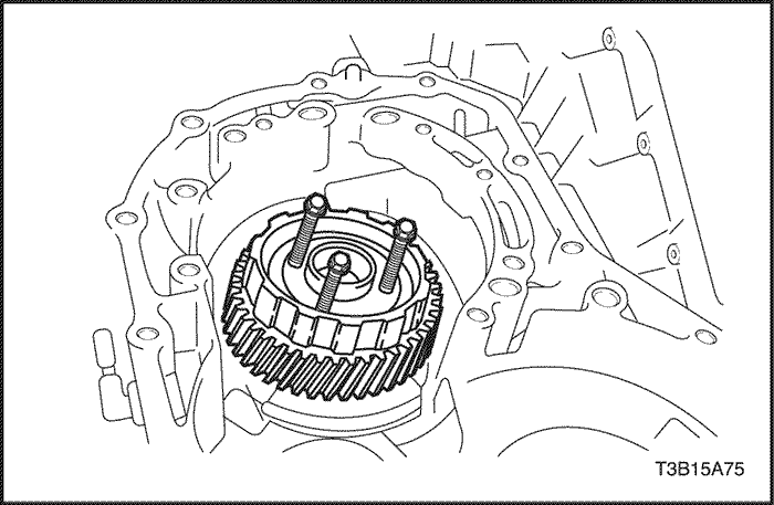
- Install the 3 bolts to the counter drive gear.
- Bolt (M6) : L= 40-80mm, Pich = 1.0mm
- Rotate 3 bolts in order and remove the counter drive gear and planetary ring gear.
USE CAUTION WHEN REMOVING SNAP RINGS OR PERSONAL INJURY MAY RESULT.
- Using brake spring compressor bolt/nut DW240-060-01 and 1st & reverse brake adapter DW240-070, remove the snap ring of 1st & reverse brake.
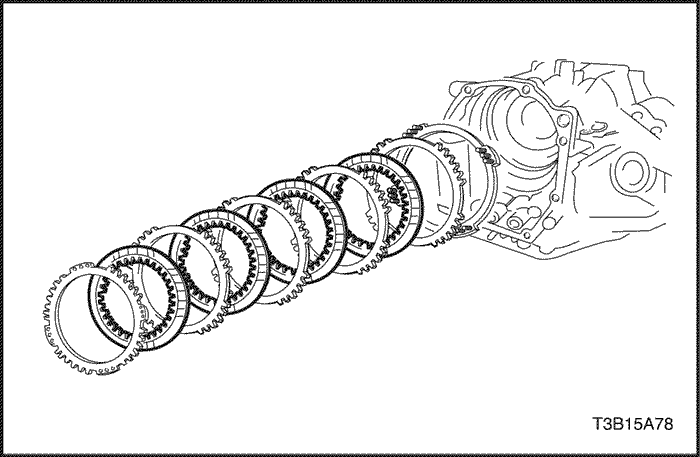
- Remove the flange, 4 discs, 4 plates and return spring.
USE CAUTION WHEN REMOVING COMPONENTS WITH COMPRESSED AIR OR PERSONAL INJURY MAY RESULT.
Notice : Blowing off the air may cause the piston's jump-out. When removing the piston, hold it with your hand using a waste cloth.
Notice : Take care not to splash ATF when air-blowing
- Apply 392 kPa (57 psi) of compressed air to the transaxle case to remove the 1st & reverse brake piston.
- Remove the 2 O-rings from the 1st & reverse brake piston.
- Remove the bolt and No.1 transaxle case plate from the transaxle case.
- Using a suitable puller, remove the counter driven gear outer tapered roller bearing race and shim from the transaxle case.
- Using a driver, remove the oil seal from the transaxle case.
Notice : Be careful not to damage the transaxle case when removing the oil seal using a driver.
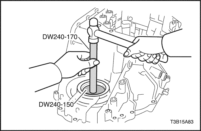
- Using transaxle case side bearing outer race adapter DW240-150 and adapter handle DW240-170, remove the transaxle case side bearing outer race and shim.
- Remove the 3 bolts and oil reservoir lock plate from the transaxle housing.
- Remove the bolt and No.1 transaxle apply pipe clamp from the transaxle housing.
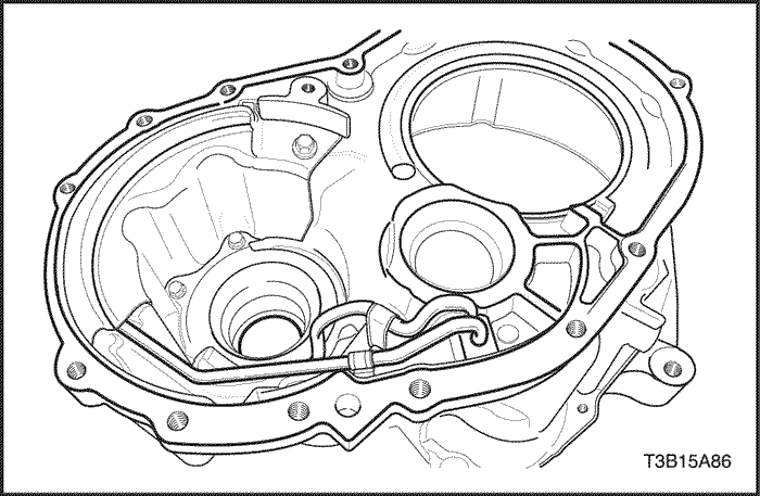
- Remove the transaxle lube apply pipe and differential gear lube apply pipe from the transaxle housing.
- Using a suitable puller, remove the counter driven gear outer tapered roller bearing race from the transaxle housing.
- Using a driver, remove the oil seal from the transaxle housing.
Notice : Be careful not to damage the transaxle housing when removing the oil seal using a driver.
- Using a suitable puller, remove the side bearing outer race from the transaxle housing.
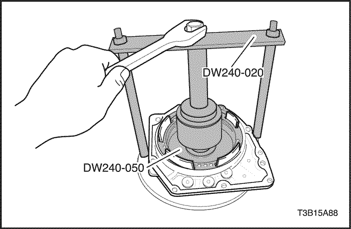
USE CAUTION WHEN REMOVING SNAP RINGS OR PERSONAL INJURY MAY RESULT.
Notice : Stop the press when the O/D brake piston is lowered 1-2 mm (0.039-0.078 in.) from the snap ring groove, preventing the O/D brake piston from being deformed.
- Using brake/clutch spring compressor DW240-020, overdrive brake adapter DW240-050 and a driver, remove the snap ring.
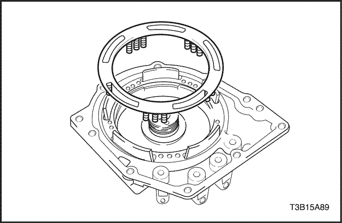
- Remove the O/D brake return spring.
USE CAUTION WHEN REMOVING COMPONENTS WITH COMPRESSED AIR OR PERSONAL INJURY MAY RESULT.
Notice : Blowing off the air may cause the piston's jump-out.When removing the piston, hold it with your hand using a waste cloth.
Notice : Take care not to splash ATF when air-blowing.
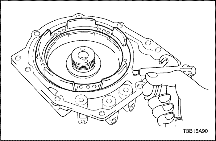
- Apply 392 kPa (57 psi) of compressed air to the transaxle rear cover to remove the O/D brake piston.
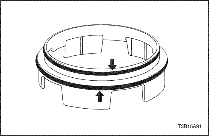
- Remove the 2 O-rings from the O/D brake piston.
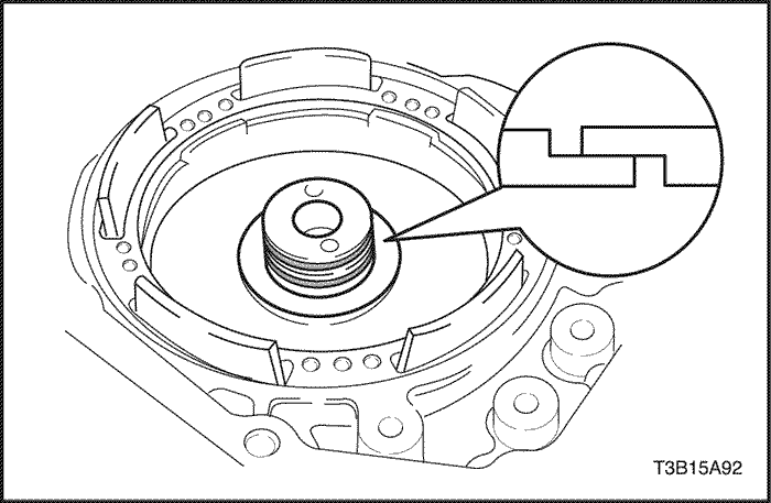
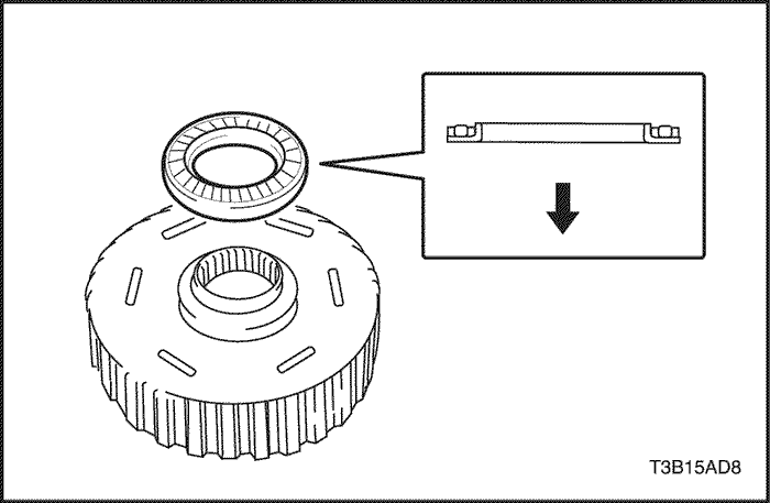
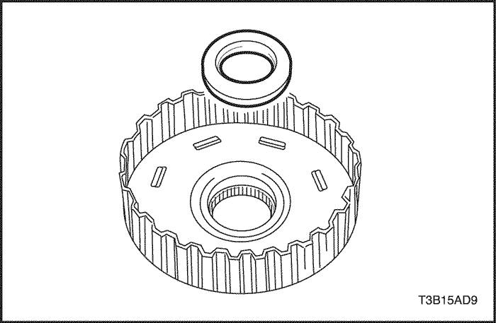
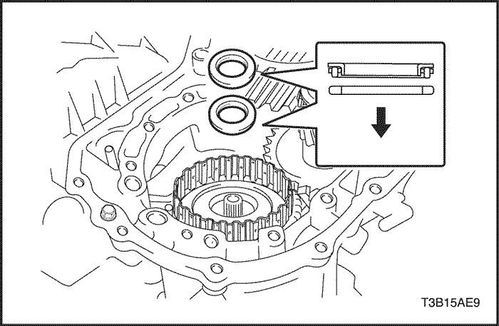
- Remove the 2 seal rings from the transaxle rear cover.
Notice : Do not expand the seal ring excessively.
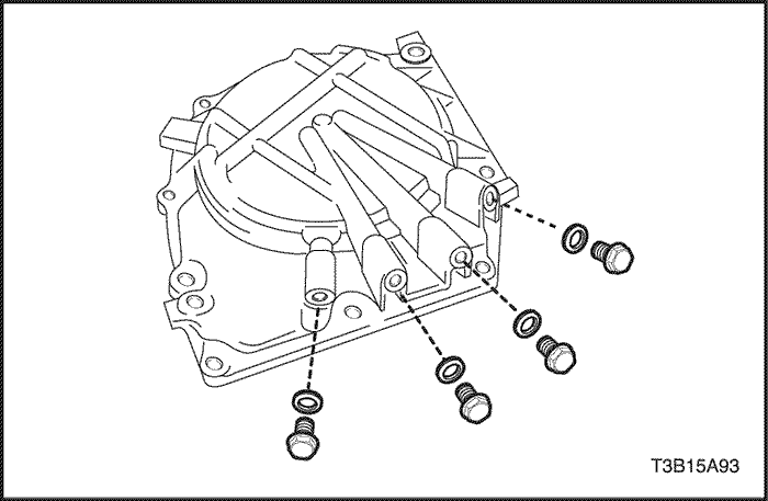
- Remove the 4 screw plugs and 4 O-rings from the transaxle rear cover.
DW240-020 Brake/Clutch Spring Compressor
DW240-050 Overdrive Brake Adapter
DW240-060-01 Brake Spring Compressor Bolt/Nut
DW240-060-02 Brake Spring Compressor Plate
DW240-070 1st / Reverse Brake Adapter
DW240-100 Counter Drive Gear Installation Adapter
DW240-130 Differential Preload Adapter
DW260-031-01 Transaxle Housing Oil Seal Installer
DW260-031-02 Transaxle Case Oil Seal Installer
DW260-041 Planetary Ring Gear Nut Removal/Installation Socket
DW240-160 Transaxle Case Outer Tapered Roller Bearing Race Adapter
DW240-140 Transaxle Housing Side Bearing Outer Race Adapter
DW240-170 Adapter Handle
- Install 4 new O-rings to the 4 screw plugs.
- Install the 4 screw plugs with the O-rings to the transaxle rear cover.
Tighten
Tighten the screw plugs to 7.4 N•m (65 lb-in).
- Install the 2 seal rings to the transaxle rear cover.
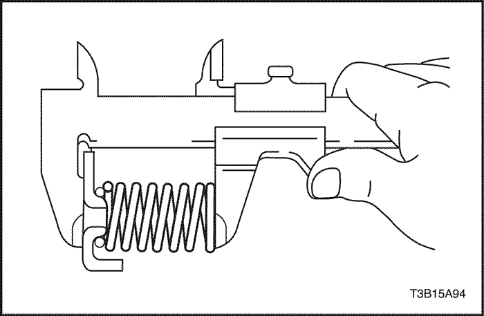
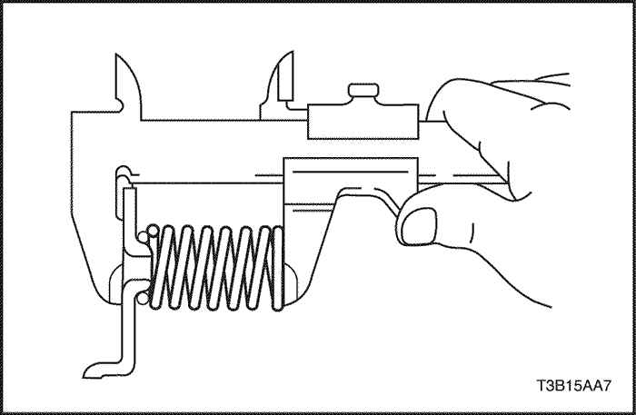
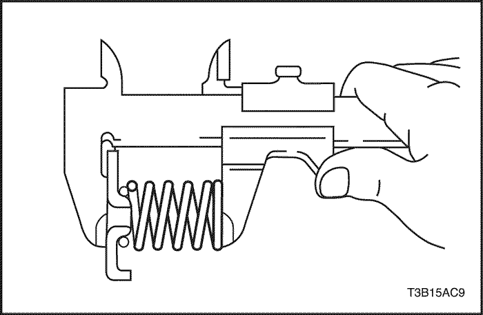
- Using the vernier calipers, measure the free length of the O/D brake piston return spring together with the spring seat.
- Standard free length : 18.99 mm (0.7476 in.)
- Coat 2 new O-rings with ATF, install them to the O/D brake piston.
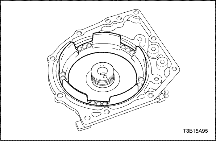
- Coat the O/D brake piston with ATF, install it to the transaxle rear cover.
Notice : Be careful not to damage the O-rings of the O/D brake piston.
- Using brake/clutch spring compressor DW240-020, overdrive brake adapter DW240-050 and a driver, install the O/D brake return spring and snap ring to the transaxle rear cover.
Notice : Stop the press when the O/D brake piston is lowered 1-2 mm (0.039 –0.078 in.) from the snap ring groove, preventing the O/D brake piston from being deformed.
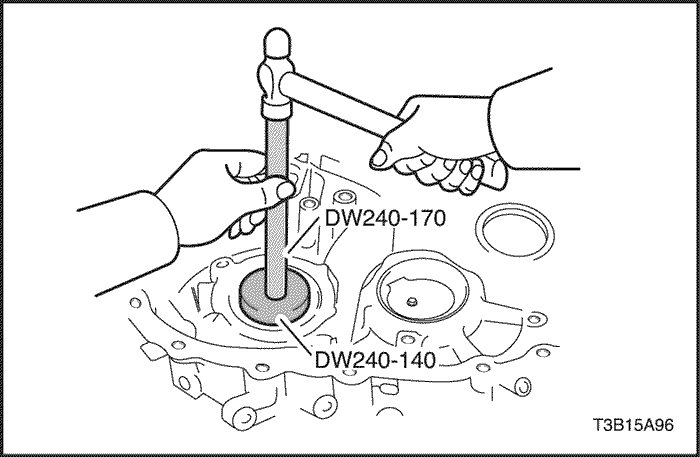
- Using transaxle housing side bearing outer race adapter DW240-140 and adapter handle DW240-170, install a new side bearing outer race into the transaxle housing.
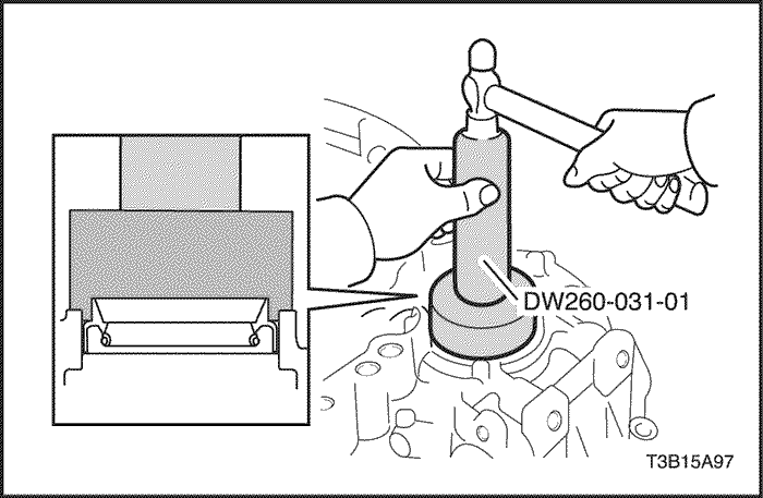
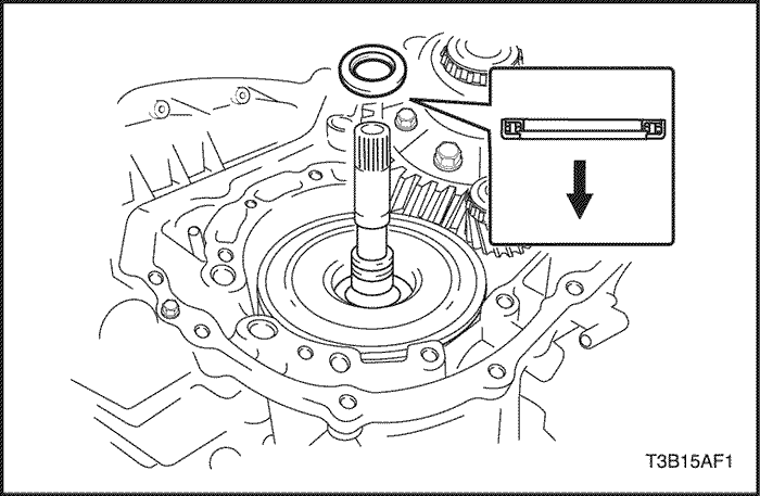
- Using transaxle housing oil seal installer DW260-031-01 and a hammer, drive in a new transaxle housing oil seal.
- Oil seal in depth: 3.1mm (0.122 in.)
- Install a new outer tapered roller bearing race into the transaxle housing.
Notice : Press –fit the outer tapered roller bearing race until it contacts the transaxle housing.
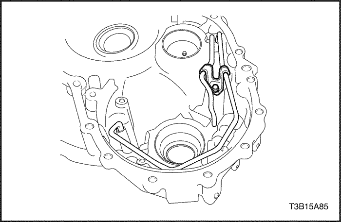
- Install the transaxle lube apply pipe and differential gear lube apply pipe to the transaxle housing.
- Install the No.1 transaxle apply pipe clamp to the transaxle housing with the bolt.
Tighten
Tighten the bolt to 5.4 N•m (48 lb-in).
- Install the oil reservoir lock plate to the transaxle housing with the 3 bolts.
Tighten
Tighten the bolts to 5.4 N•m (48 lb-in).
- Install the shim to the transaxle case.
Notice : First install a shim of the same thickness as before.
- Install a new bearing outer race into the transaxle case.
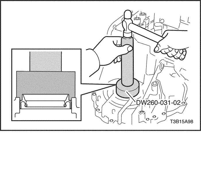
- Using transaxle case oil seal installer DW260-031-02 and a hammer, drive in a new transaxle case oil seal.
- Oil seal in depth: 4.3 mm (0.169 in.)
- Install the shim to the transaxle case.
Notice : First install a shim of the same thickness as before.
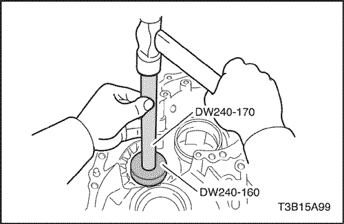
- Using transaxle case outer tapered roller bearing race adapter DW240-160 and adapter handle DW240-170, press in a new outer tapered roller bearing race into the transaxle case.
Notice : Press-fit the shim until it contacts the transaxle case.
- Install the No.1 transaxle case plate to the transaxle case with the bolt.
Tighten
Tighten the bolt to 9.8 N•m (87 lb-in).
- Install the differential gear to the transaxle case.
- Install the transaxle housing and tighten the 16 bolts of the transaxle housing temporarily.
- Tighten 8 or 9 bolts out of 16 bolts of the transaxle housing completely.
Tighten
Tighten the bolt to 29 N•m (22 lb-ft).
- Using differential preload adapter DW240-130, turn the differential gear assembly right and left 2 or 3 times to allow the bearing settle.
- Using differential preload adapter DW240-130 and small torque wrench, measure the preload of the differential gear.
Notice : Note down the measured valve.
- Remove the transaxle housing and install the counter driven gear.
- Install the transaxle housing and tighten the 16 bolts of the transaxle housing temporarily.
- Tighten the bolts of the transaxle housing in the same manner as in step 22.
Tighten
Tighten the bolts to 29 N•m (22 lb-in).
- Using differential preload adapter DW240-130, turn the differential gear assembly right and left 2 or 3 times to allow the bearing settle.
- Using differential preload adapter DW240-130 and a small torque wrench, measure the preload of the differential gear. From this valve deduct the valve measured in step 23. This is the preload of the counter driven gear.
-
- New bearing: 0.33-0.76 N•m (3.21-6.77 lb-in)
- Used bearing: 0.17-0.38 N•m (1.48-3.39 lb-in)
If the preload of counter driven gear does not satisfy the specification, select the adjuster shim from the table below and remeasure the valve. Until the valve is within the specification, repeat the procedure.
Notice : When the preload is larger than the specification, select a thinner adjuster shim. When the preload is smaller than specification, select a thicker adjuster shim.
- Adjuster shim thickness: mm (in.)
Mark
|
Thickness
|
Mark
|
Thickness
|
|
1
|
1.70 (0.0669)
|
G
|
2.17 (0.0854)
|
|
2
|
1.75 (0.0689)
|
H
|
2.20 (0.0866)
|
|
3
|
1.80 (0.0709)
|
K
|
2.25 (0.0886)
|
|
4
|
1.85 (0.0728)
|
L
|
2.30 (0.0906)
|
|
5
|
1.90 (0.0748)
|
M
|
2.35 (0.0925)
|
|
6
|
1.93 (0.0760)
|
N
|
2.40 (0.0945)
|
|
7
|
1.96 (0.0772)
|
P
|
2.45 (0.0965)
|
|
A
|
1.99 (0.0783)
|
Q
|
2.50 (0.0984)
|
|
B
|
2.02 (0.0795)
|
R
|
2.55 (0.1004)
|
|
C
|
2.05 (0.0807)
|
S
|
2.60 (0.1024)
|
|
D
|
2.08 (0.0819)
|
U
|
2.65 (0.1043)
|
|
E
|
2.11 (0.0831)
|
W
|
2.70(0.1063)
|
|
F
|
2.14 (0.0843)
|
-
|
-
|
- Using the vernier calipers, measure the free length of the 1st & reverse brake piston return spring together with spring seat.
- Standard free length: 18.053 mm (0.71075 in.)
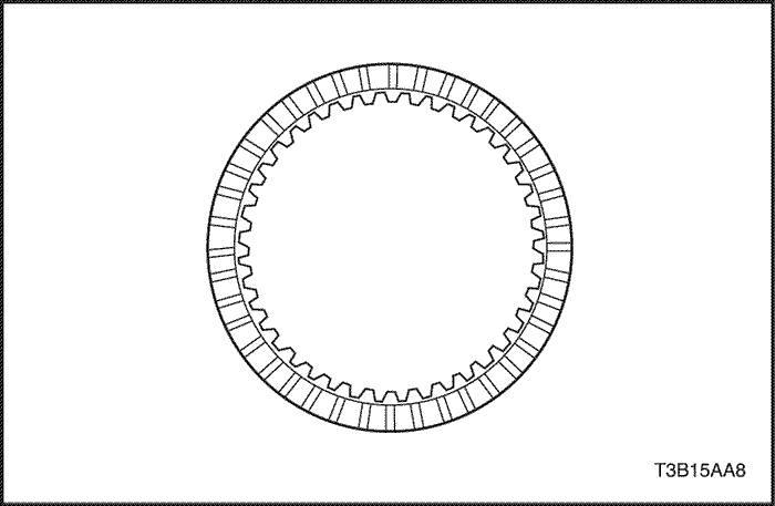
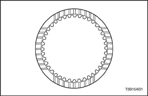
- Check to see if the sliding surface of the disc, plate and flange of 1st & reverse brake are worn or burnt. If necessary, replace them.
Notice : If the lining of the disc is peeling off or discolored, or even if a part of the groove is defaced, replace all discs.
Notice : Before assembling new discs, soak them in ATF for at least 15 minutes.
- Coat 2 new O-rings with ATF, install them to the 1st & reverse piston.
- Install the 1st & reverse brake piston to the transaxle case.
Notice : Be careful not to damage the O-rings of the 1st & reverse brake piston.
- Install the return spring to the transaxle case.
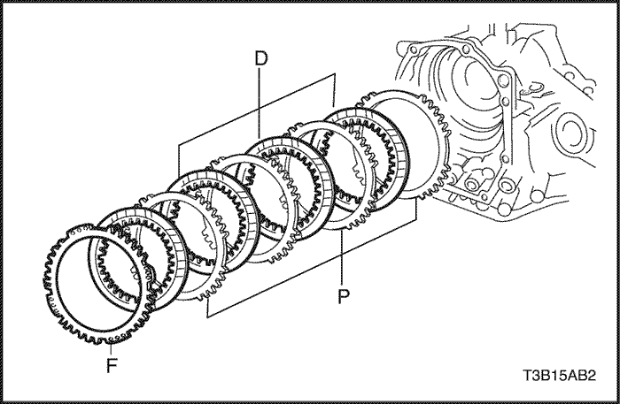
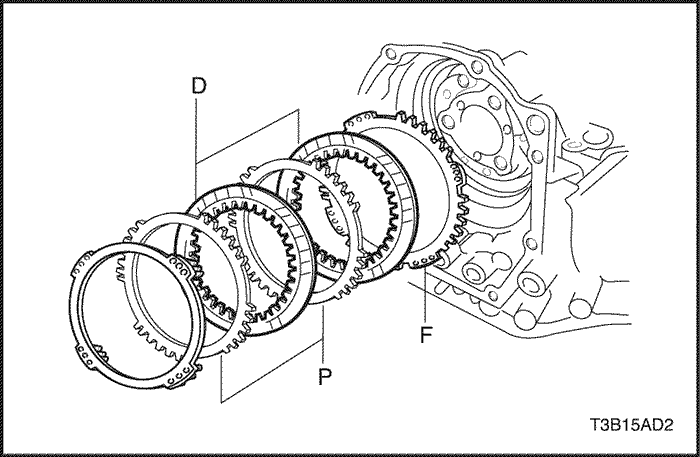
- Install the 4 plates, 4 discs and flange.
- Install in order : P – D – P – D – P – D – P – D – F
-
- (P= Plate, D= Disc, F= Flange)
- Using 1st & reverse brake adapter DW240-070 and brake spring compressor bolt/nut DW240-060-01, install the snap ring.
Notice : Make sure that the snap ring is installed in the groove of the transaxle case correctly.

- Using a dial indicator, measure the 1st & reverse brake piston stroke while applying and releasing 392-785 kPa (57-114 psi) of compressed air.
Notice : If the piston stroke is non-standard, inspect the discs, plates and flange. Piston stroke 0.6 – 1.3 mm (0.024 – 0.051 in.)
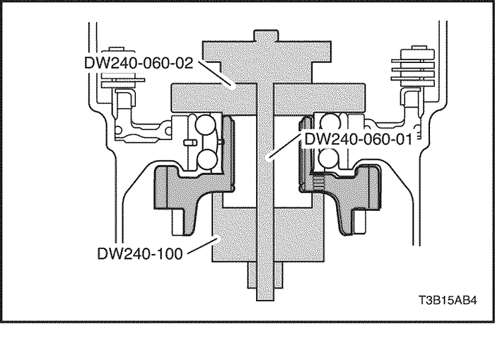
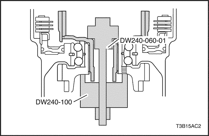
- Using counter drive gear installation adapter DW240-100, brake spring compressor bolt/nut DW240-060-01 and brake spring compressor plate DW240-060-02, install the counter drive gear.
- Using counter drive gear installation adapter DW240-100, brake spring compressor bolt/nut DW240-060-01 and brake spring compressor plate DW240-060-02, install the counter drive gear.
Notice : Be careful not to apply excessive force to the transaxle case.
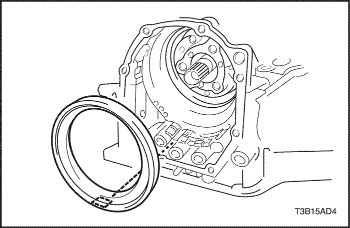
- Coat a new oil seal with ATF.
- Coat a new oil seal with ATF.
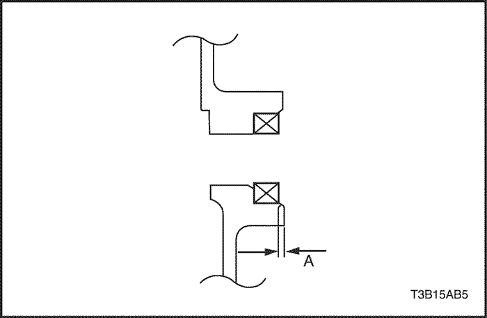
- Install the oil seal to the transaxle case.
- Install the oil seal to the transaxle case.
-
- A: 1 ± 0.25 mm (0.39 ± 0.0098 in.)
- Install the parking lock rod to the manual valve lever.
- Install the parking lock rod to the manual valve lever.
- Install a new spacer to the manual valve lever.
- Install a new spacer to the manual valve lever.
- Install the manual valve lever shaft and manual valve lever.
- Install the manual valve lever shaft and manual valve lever.
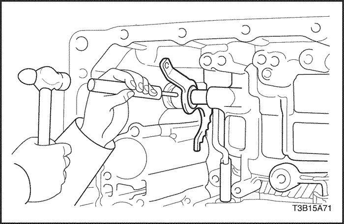
- Using a pin punch and hammer, drive in a new pin.
- Turn the spacer and lever shaft to align the small hole for locating the staking position in the spacer with the staking position mark on the lever shaft.
- Turn the spacer and lever shaft to align the small hole for locating the staking position in the spacer with the staking position mark on the lever shaft.
- Using a pin punch, stake the spacer through the small hole.
- Using a pin punch, stake the spacer through the small hole.
- Check that the spacer does not turn.
- Install the manual detent spring with the bolt.
Tighten
Tighten the bolts to 9.8 N•m (87 lb-in).
- Install the parking lock shaft, torsion spring and parking lock pawl.
Notice : Check that the edge of torsion spring fits into the groove securely.
- Install the parking lock pawl bracket with the 2 bolts.
Tighten
Tighten the bolts to 7.4 N•m (65 lb-in).
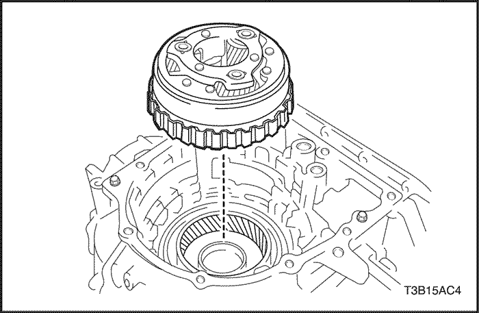
- Using counter drive gear installation adapter DW240-100 and brake spring compressor bolt/nut DW240-060-01,install the planetary ring gear.
- Before installing the planetary ring gear, be sure to replace the planetary ring flange of the planetary ring gear with a new one.
- Fix the counter drive gear with parking lock pawl.
- Using planetary ring gear nut removal/installation socket DW260-041, install a new nut.
Tighten
Tighten the nut to 9.8 N•m (87 lb-in).
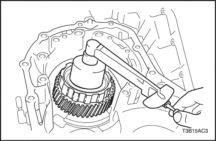
- Using a small torque wrench, while turning to counter drive gear 100 turn per minute and measure the preload.
Notice : When the preload is smaller than the specification, tighten the nut more and adjust the preload. Preload: 0.05-0.35 N•m (0.43-3.12 lb-in)
Tighten
Tighten the nut to 29 N•m (22 lb-ft) or less.
- Stake the nut.
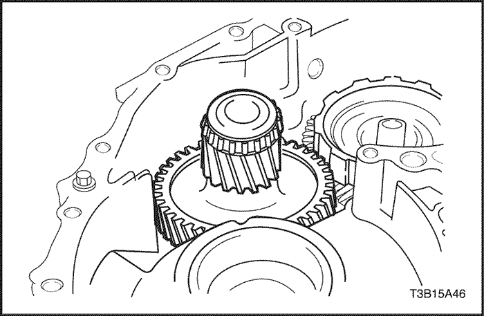
- Install the planetary gear to the transaxle case.
- Coat the planetary carrier thrust washer with petroleum jelly and install it onto the planetary gear.
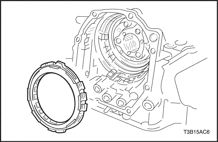
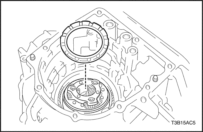
- Install the No.2 one-way clutch to the transaxle case.
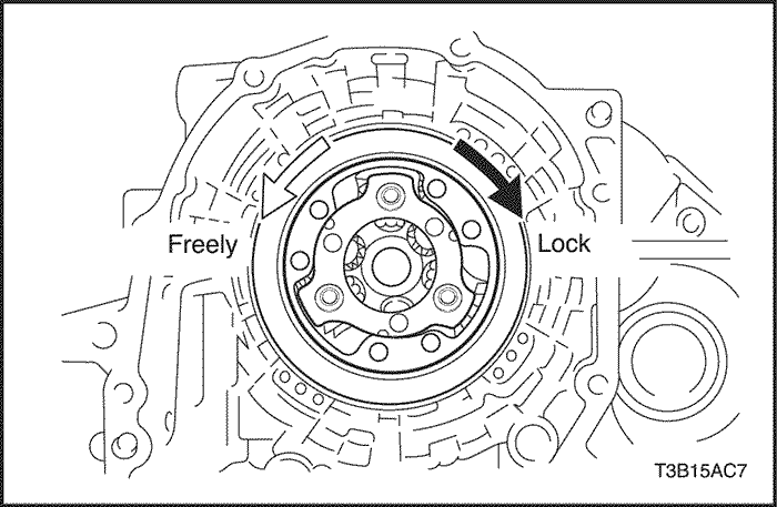
- Check that the planetary gear turns freely counterclockwise and locks clockwise.
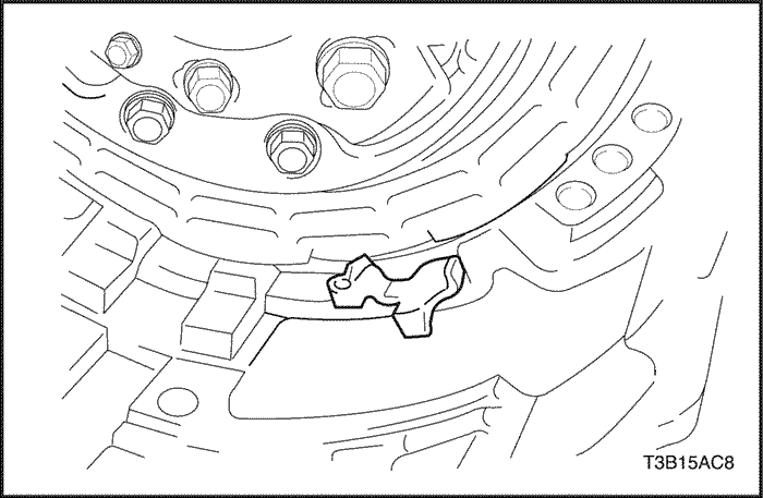
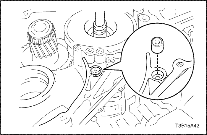
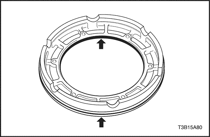
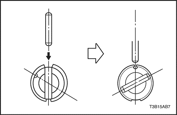
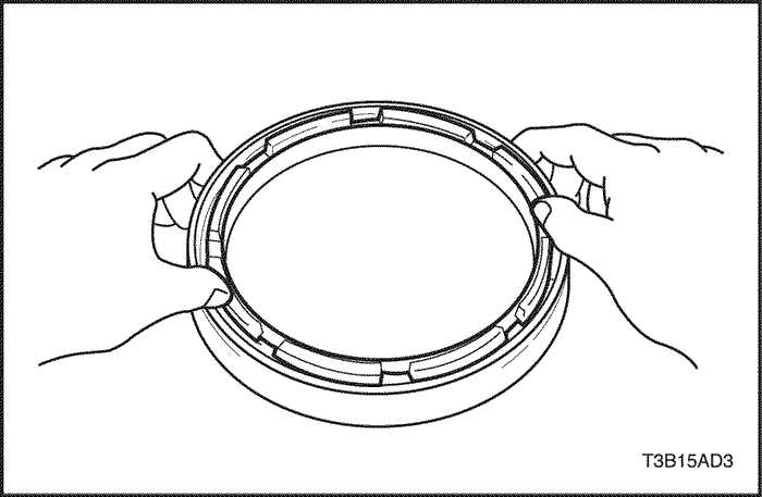
- Install the anti-rattle clip in the place shown in the illustration (the space between the No.2 one-way clutch outer race and transaxle case), push the anti-rattle clip in until you hear the "click".
- Install the anti-rattle clip in the place shown in the illustration (the space between the No.2 one-way clutch outer race and transaxle case), push the anti-rattle clip in until you hear the "click".
- Using vernier calipers, measure the free length of the 2nd brake piston return spring together with spring seat.
- Standard free length: 15.85 mm (0.6240 in.).
- Check to see if the sliding surface of the disc, plate and flange of 2nd brake are worn or burnt. If necessary, replace them.
Notice : If the lining of the disc is peeling off or discolored, or even if a part of the groove is defaced, replace all discs.
Notice : Before assembling new discs, soak them in ATF for at least 15 minutes.
- Install the flange, 2 discs and 2 plates.
- Install in order : F – D – P – D – P
-
- (D = Disc, P = Plate, F = Flange)
- Install the 2nd brake return spring.
- Install the 2nd brake return spring.
Notice : Make sure that the snap ring is installed in the groove of the transaxle case correctly.
- Coat 2 new O-rings with ATF, install them to the 2nd brake piston.
- Install the 2nd brake piston into the 2nd brake clutch cylinder.
Notice : Be careful not to damage the O-rings.
- Install the 2nd brake clutch cylinder to the transaxle case.
- Using brake spring compressor bolt / nut DW240-060-01 and 2nd brake adapter DW240-080, compress the 2nd brake piston return spring.
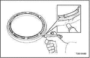
- Using a screwdriver, install the snap ring.
- Using a screwdriver, install the snap ring.
Notice : Make sure that the snap ring is installed in the groove of the transaxle case correctly.
- Coat the thrust bearing race with petroleum jelly and install it onto the front planetary sun gear.
-
- Inner diameter: 19.3 mm (0.760 in.)
- Outer diameter : 29.0 mm (1.142 in.)
- Install the front planetary sun gear to the transaxle case.
- Install the thrust washer and one-way clutch assembly to the rear planetary sun gear.
- Coat the thrust bearing race with petroleum jelly and install it onto the rear planetary sun gear and one-way clutch assembly.
-
- Inner diameter: 42.5 mm (1.673 in.)
- Outer diameter: 57.5 mm (2.264 in.)
Notice : Check the direction of the bearing.
- Install the rear planetary sun gear and one-way clutch assembly to the transaxle case.
- Coat the thrust bearing race with petroleum jelly and install it onto the transaxle case.
- Coat the thrust bearing race with petroleum jelly and install it onto the transaxle case.
-
- Inner diameter: 34.95 mm (1.3760 in.)
- Outer diameter: 45.50 mm (1.7913 in.)
Notice : Check the direction of race.
- Coat the thrust needle roller bearing with petroleum jelly and install it onto the forward clutch hub.
-
- Inner diameter: 33.3 mm (1.311 in.)
- Outer diameter: 46.5 mm (1.831 in.)
Notice : Check the direction of bearing.
- Install the forward clutch hub to the transaxle case.
- Coat the thrust bearing race with petroleum jelly and install it onto the forward clutch hub.
-
- Inner diameter: 19.3 mm (1.760 in.)
- Outer diameter: 30.6 mm (1.205 in.)
- Install the thrust bearing race and thrust needle roller bearing to the forward & reverse clutch assembly.
- Race and bearing diameter: mm(in.)
.
|
Inner diameter
|
Outer diameter
|
|
Race
|
18.1 (0.713)
|
28.2 (1.110)
|
|
Bearing
|
18.1 (0.713)
|
29.6 (1.165)
|
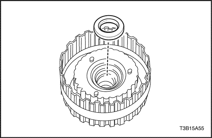
- Install the forward & reverse clutch assembly to the transaxle case.
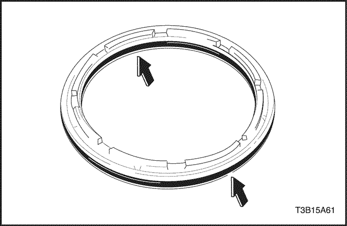
- Check to see if the sliding surface of the disc, plate and flange of 2nd coast & O/D brake are worn or burnt. If necessary, replace them.
Notice : If the lining of the disc is peeling off or discolored, or even if a part of the printed mark is defaced, replace all discs.
Notice : Before assembly new discs, soak them in ATF for at least 15 minutes.
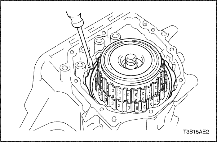
- Using a screwdriver, install the snap ring to the transaxle case.
Notice : Make sure that the snap ring is installed in the groove of the transaxle case correctly.
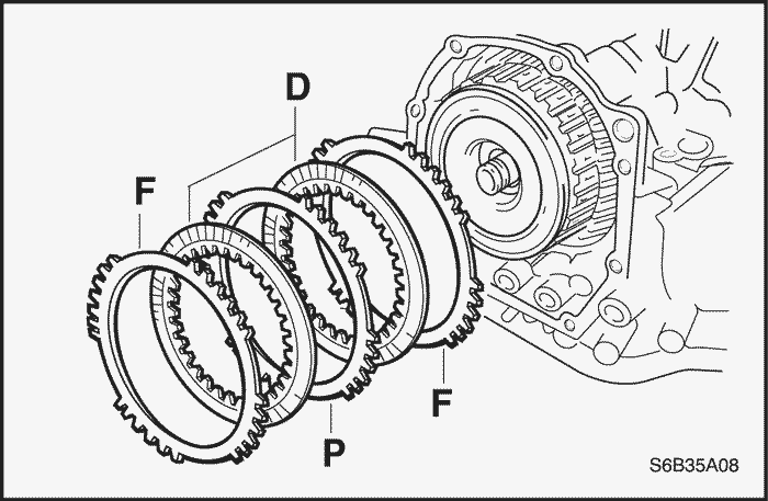
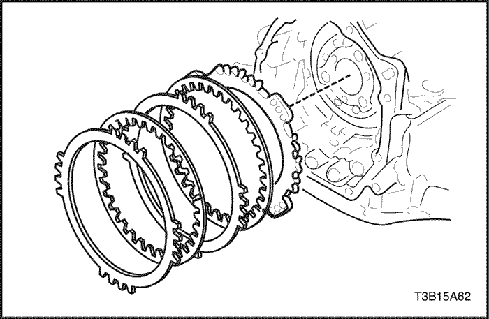
- Install the 2 flanges, 2 discs and 1 plate to the transaxle case.
- Install in order: F – D – P – D – F
-
- (P = Plate, D = Disc, F = Flange)
- Clean the connected part the transaxle case and transaxle rear cover.
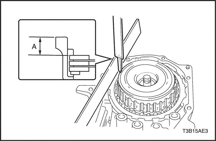
- As shown in the illustration, place a straight edge on the transaxle case and measure the distance between the 2nd coast & O/D brake flange and straight edge using vernier calipers. (Dimension A).
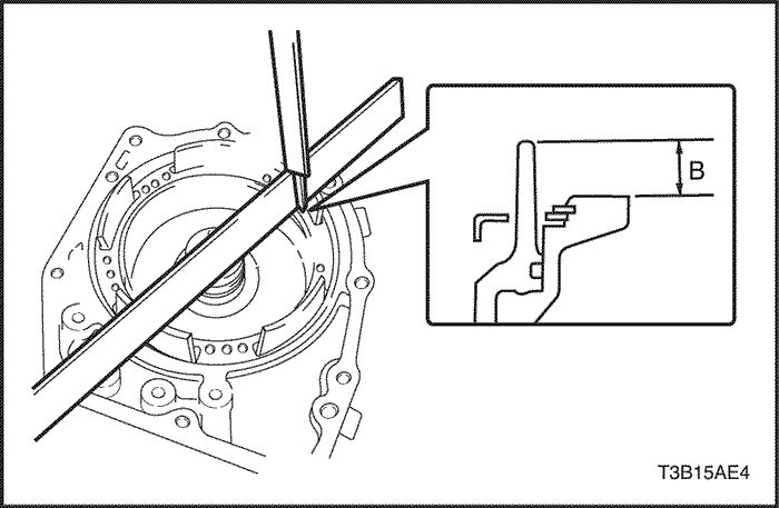
- As shown in the illustration, place a straight edge on the O/D brake piston and measure the distance between the transaxle rear cover and straight edge using vernier calipers. (Dimension B).
- Calculate the piston stroke value using the following formula. Select a flange which satisfies the piston stroke value and install it.
-
- Piston stroke = Dimension A – Dimension B
- Piston stroke : 0.65 – 1.05 mm (0.0256 – 0.0413 in.)
- Flange thickness : mm (in.)
Thickness
|
Mark
|
|
1.8 (0.071)
|
1
|
|
2.0 (0.079)
|
2
|
|
2.2 (0.087)
|
3
|
|
2.4 (0.094)
|
4
|
|
2.6 (0.102)
|
5
|
- Install new 4 apply gaskets to the transaxle rear cover.
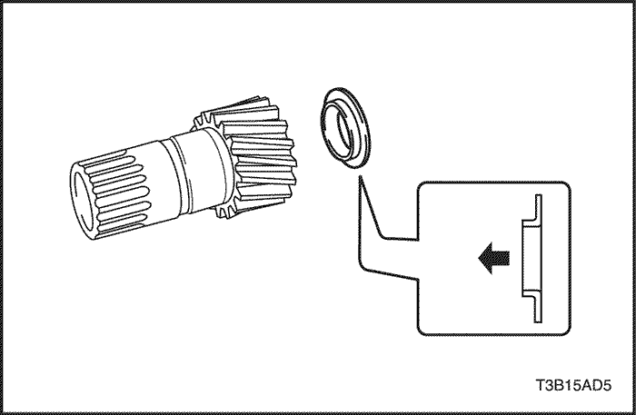
- Coat the thrust neddle roller bearing with petroleum jelly and install it onto the forward & reverse clutch assembly.
-
- Inner diameter: 43.2 mm (1.701 in.)
- Outer diameter: 62.0 mm (2.441 in.)
- Remove any packing material and be careful not to get oil on the contacting surfaces of the transaxle rear cover or transaxle case.
- Apply formed in place gasket (FIPG) to the transaxle rear cover.
-
- FIPG: three bond 1281 or equivalent
- Seal bend width: 1.2 mm (0.047 in.)
- Install the transaxle rear cover to the transaxle case with the 9 bolts.
Tighten
Tighten the bolts to 25 N•m (18 lb-ft).
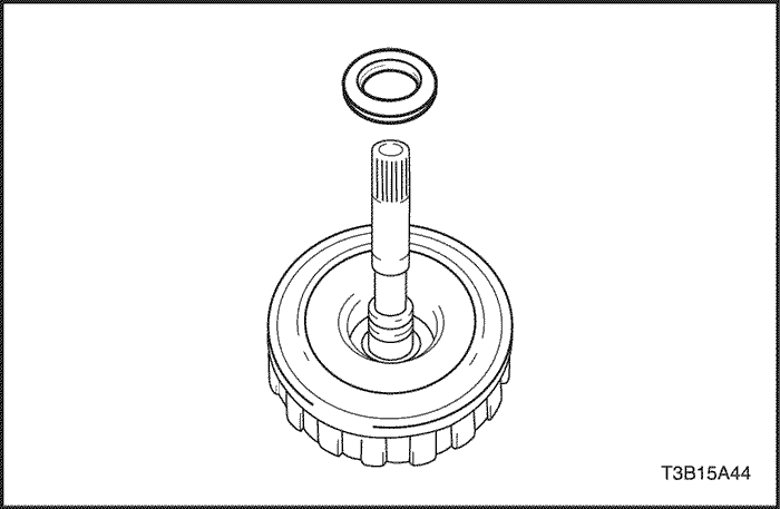
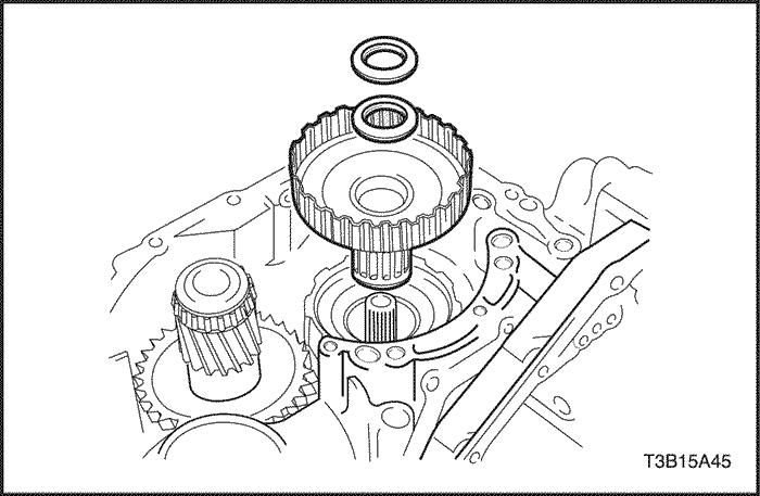
- Install the counter driven gear assembly to the transaxle case.
- Install the differential gear assembly to the transaxle case.
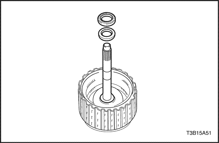
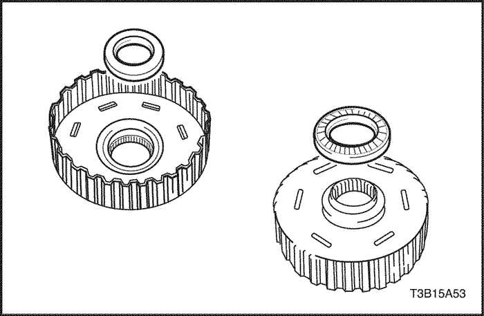
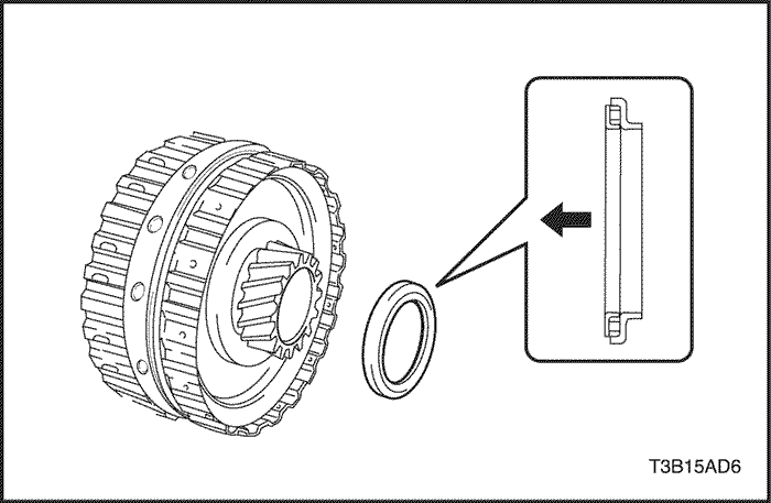
- Install the direct clutch hub to the transaxle case.
- Install the thrust bearing race and thrust needle roller bearing to the transaxle case.
- Race and bearing: mm (in.)
.
|
Inner diameter
|
Outer diameter
|
|
Race
|
20.5 (0.807)
|
32.6 (1.283)
|
|
Bearing
|
17.8 (0.701)
|
30.2 (1.189)
|
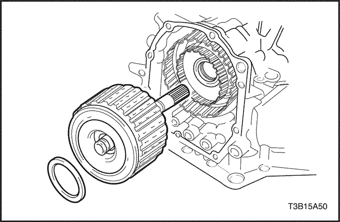
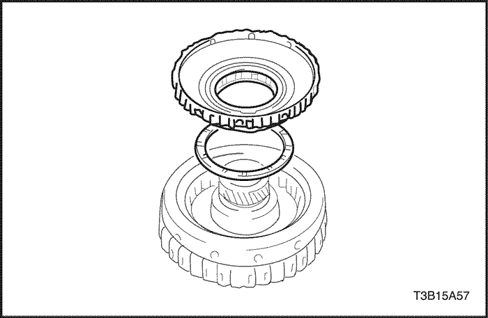
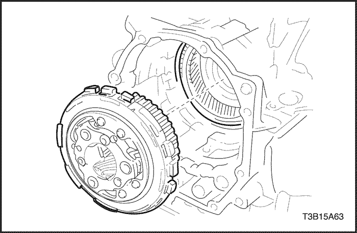
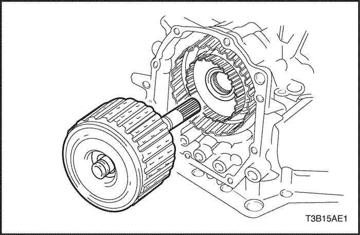
- Install the direct clutch assembly to the transaxle case.
- Install the direct clutch assembly to the transaxle case.
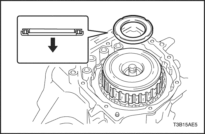
- Install new apply gasket.
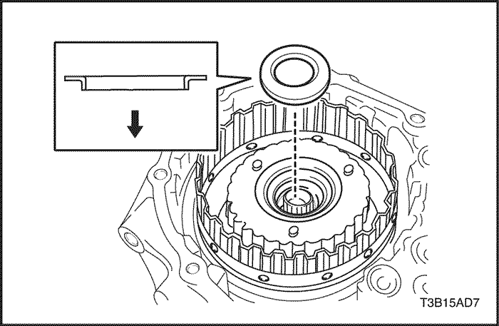
- Install the thrust needle roller bearing to the transaxle case.
Notice : Check the direction of the bearing.
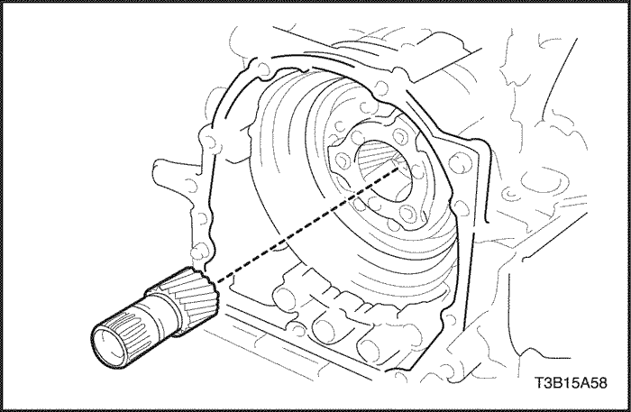
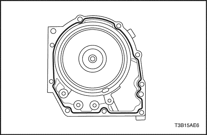
- Place the oil pump through the input shaft, and align the bolt holes of the oil pump with the transaxle case.
- Install the 6 oil pump bolts.
Tighten
Tighten the bolts to 25 N•m (18 lb-ft).
- Measure the end play in axial direction.
Notice : If the end play is not as specified, select and replace the thrust needle roller bearing.
- End play 0.3 – 0.9 mm (0.012 – 0.035 in.)
- Bearing: mm (in.)
Inner diameter
|
Outer diameter
|
Thichness
|
|
32.5 (1.280)
|
48.5 (1.909)
|
4.21 (0.1657)
|
|
32.9 (1.295)
|
48.5 (1.909)
|
3.62 (0.1425)
|
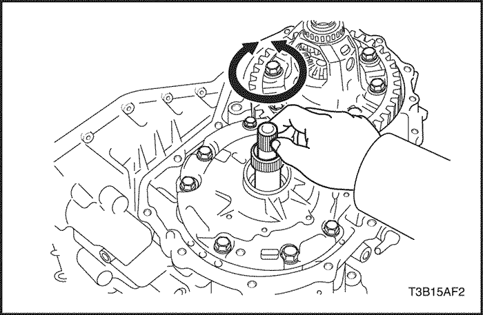
- Make sure that the input shaft rotates smoothly.
- Remove any packing material and be careful not to get oil on the contacting surfaces of the transaxle housing or transaxle case.
- Apply FIPG (formed in place gasket) to the transaxle housing.
-
- FIPG: Three bond 1281 or equivalent.
- Seal bend width: 1.2 mm (0.047 in.)
- Install the transaxle housing to the transaxle case with the 16 bolts.
Tighten
Tighten the bolts to 29 N•m (22 lb-ft).
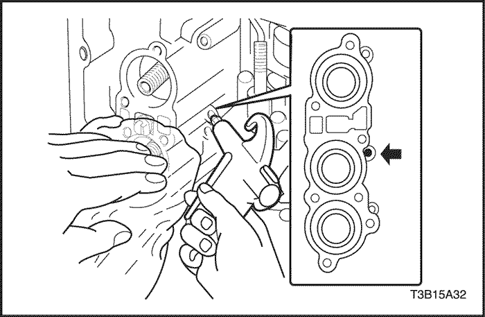
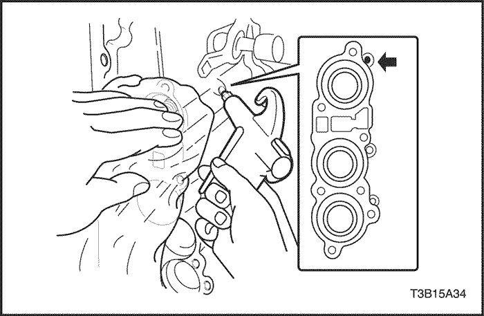
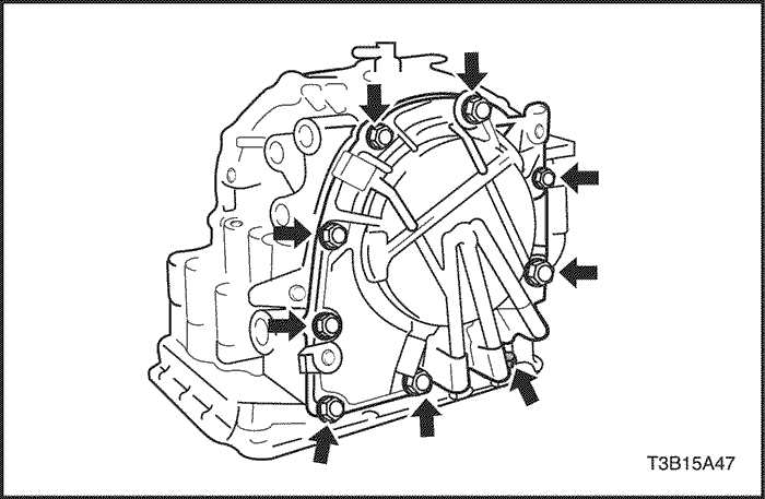
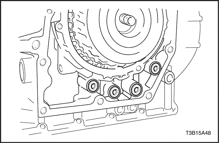
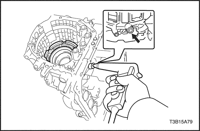
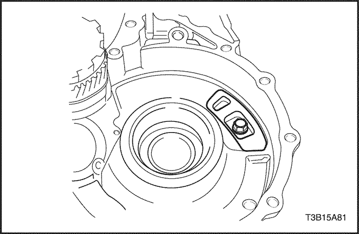
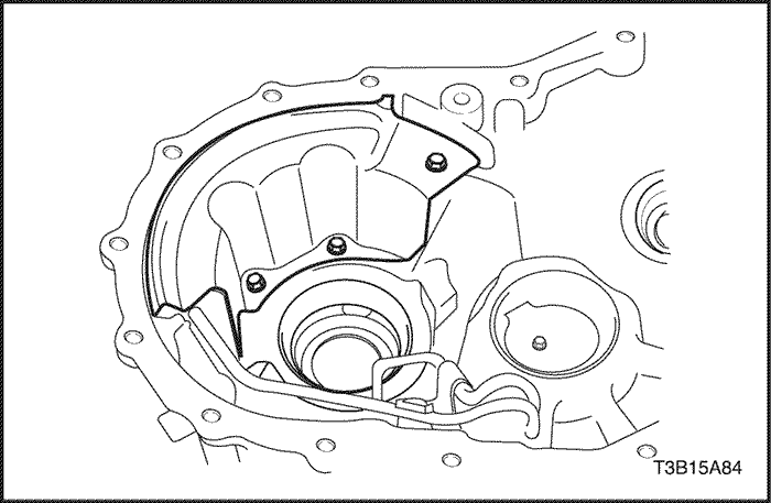
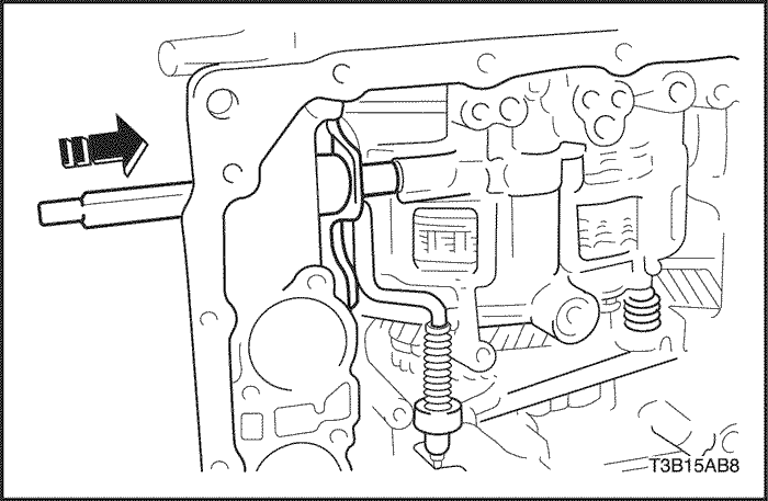
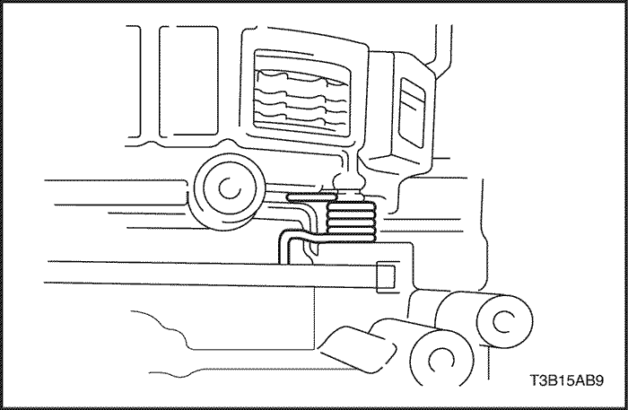
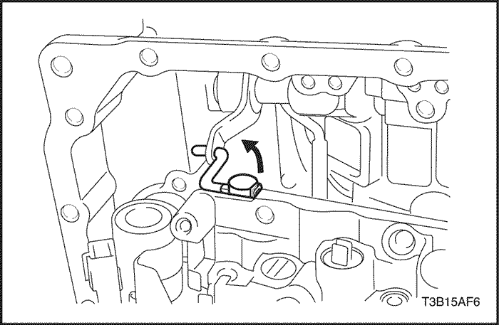
- Apply seal packing or equivalent to the 3 bolts indicated by arrows.
- Coat a new O-ring with ATF, install it to the transaxle wire.
- Install the transaxle wire the to the transaxle case with the bolt.
Tighten
Tighten the bolts to 5.4 N•m (48 lb-in).
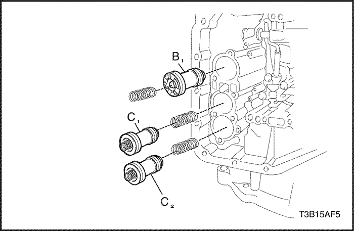
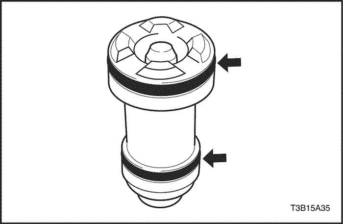
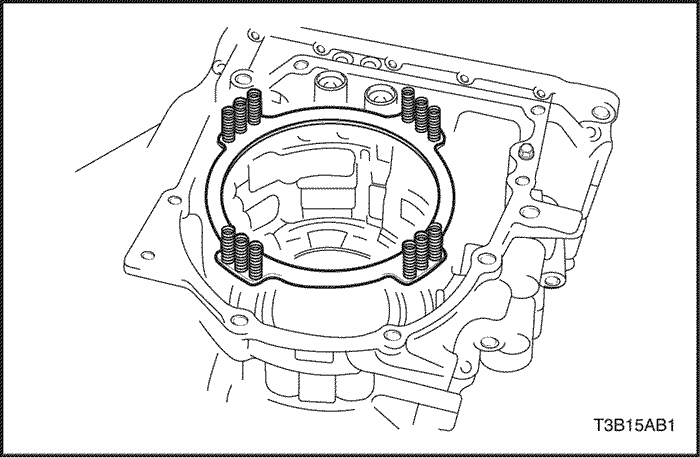
- Coat new 6 O-rings with ATF and install them to the pistons.
- Coat the 3 springs and 3 accumulator pistons with ATF, install them to the holes.
Spring
|
Free length
Outer diameter mm(in.)
|
Color
|
|
B1(O/D & 2nd brake)
|
47.13(1.8555)/16.0(0.630)
|
Pink
|
|
C1(Forward clutch)
|
57.90(2.2795)/17.2(0.677)
|
-
|
|
C2(Direct clutch)
|
57.20(2.2520)/17.5(0.689)
|
Green
|
- Coat a new apply gasket with ATF, install it to the transaxle case.
- Coat a new brake drum gasket with ATF, install it to the transaxle case.
- Install the spring and check valve.
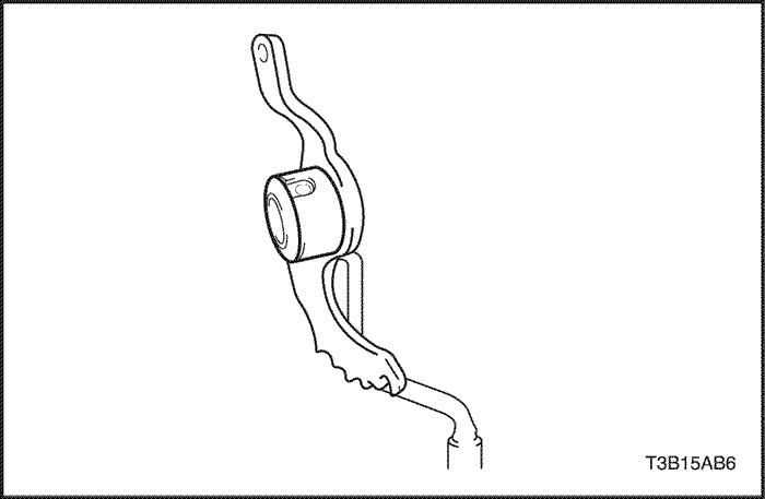
- Connect the manual valve control rod to the manual valve lever as shown in the illustration.
- Install the valve body assembly to the transaxle case.
Tighten
Tighten the bolts to 11 N•m (97 lb-in).
Notice : When installing the valve body to the transaxle case, do not let each of accumulator pistons B1,C1,and C2 incline. When installing the valve body to the transaxle case, do not hold the solenoids.
- Connect the transaxle wire connector and harness to the valve body assembly.
- Connect the 5 connectors.
-
- a. Lock-up control solenoid
- b. Pressure control solenoid.
- c. No.2 shift solenoid.
- d. No.1 shift solenoid.
- e. Timing solenoid
- Install the TFT sensor with clamp.
Notice : Make sure that the transaxle wire does not come out from the oil pan installation surface.
- Install a new gasket to the oil strainer.
- Install the oil strainer to the valve body with the 3 bolts.
Tighten
Tighten the bolts to 9.8 N•m (87 lb-in).
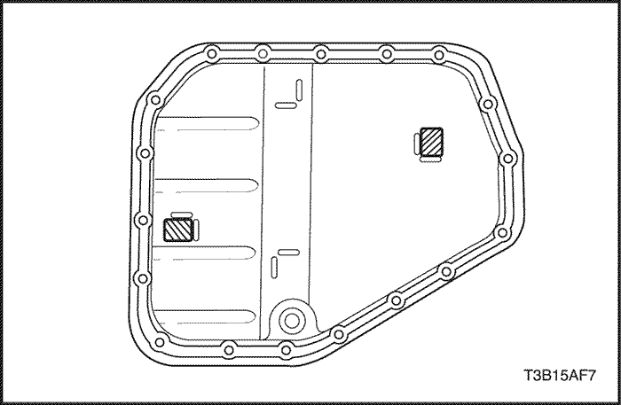
- Install the 2 magnets in the oil pan.
- Install a new gasket to the oil pan and install them to the transaxle case with the 18 bolts.
Tighten
Tighten the bolts to 7 N•m (62 lb-in).
- Install the output shaft speed (OSS) sensor.
Tighten
Tighten the bolt to 7.4 N•m (65 lb-in).
- Install the No.1 breather plug.
- Install the input shaft speed (ISS) sensor with the bolt.
Tighten
Tighten the bolts to 5.4 N•m (48 lb-in).
- Coat a new O-ring with ATF, install it to the screw plug.
- Install the screw plug to the transaxle case.
Tighten
Tighten the bolts to 7.4 N•m (65 lb-in).
- Coat new 2 O-rings with ATF, install them to the unions.
- Install the 2 unions to the transaxle case.
Tighten
Tighten the unions to 25 N•m (18 lb-ft).
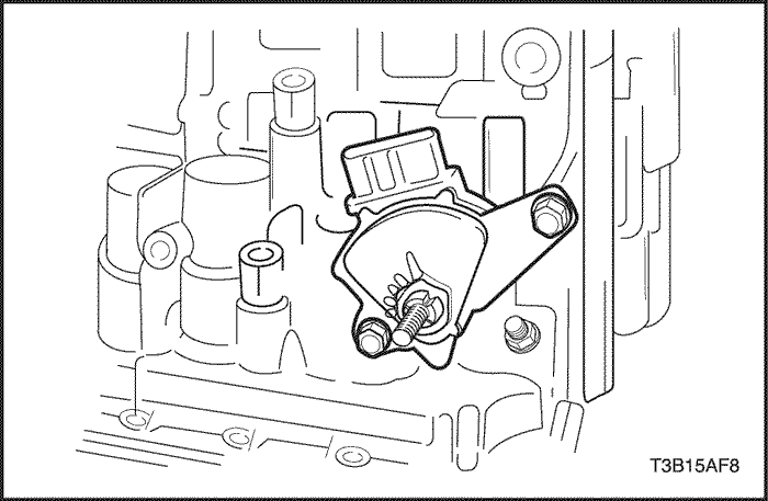
- Install the TR switch onto the manual valve lever shaft and temporarily install the 2 adjusting bolts.
- Install a new lock washer and nuts.
Tighten
Tighten the nuts to 12 N•m (106 lb-in).
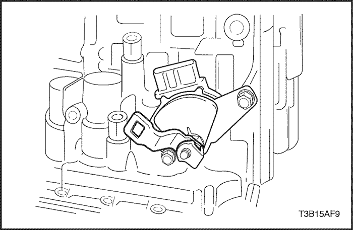
- Temporarily install the control lever.
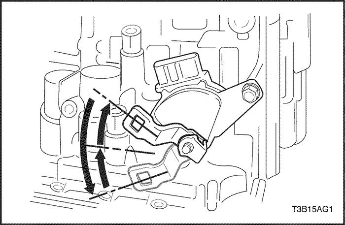
- Turn the lever counterclockwise until it stops, then turn it clockwise 2 notches.
- Remove the control lever.
- Align the groove with neutral basic line.
- Tighten the 2 bolts.
Tighten
Tighten the bolts to 5.4 N•m (48 lb-in).
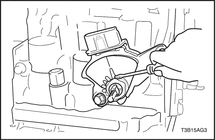
- Using a screwdriver, stake the nut with the lock washer.
- Install the control lever, washer and nut.
Tighten
Tighten the nut to 12 N•m (106 lb-in).

- Install the torque converter to the transaxle.
- Measure the installation depth of the torque converter. Standard value: 11.1 mm
-
- If the measured value is beyond the standard value, readjust the torque converter within the specified value.