MAINTENANCE AND REPAIR
ON-VEHICLE SERVICE
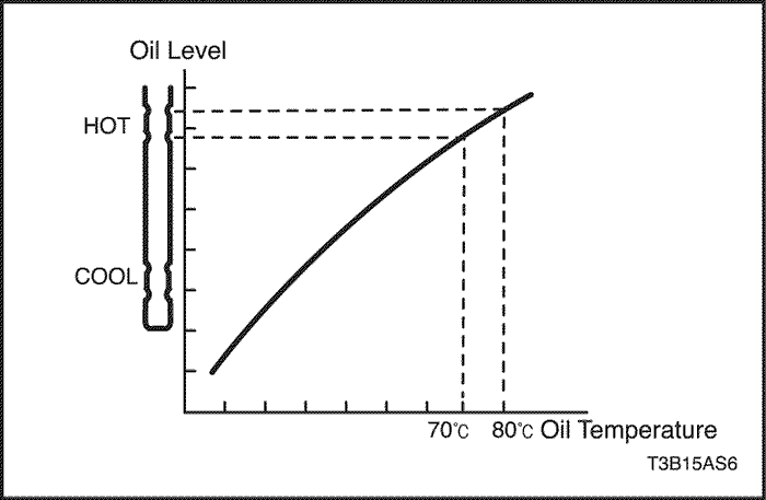


Transaxle Fluid Level Checking Procedure
Notice : Check the fluid level when the transaxle temperature is 70°C~80°C (158°F~176°F).
Notice : During the fluid level check, the selector lever must be in position P.
Notice : When adding fluid or making a complete fluid change, always use ESSO JWS 3309 or TOTAL-ISU FLUID III G. Failure to use the proper fluid will cause hose and seal damage and fluid leaks.
- Make sure the vehicle is level.
- Shift into all range from "P" to "1" and return to "P" with engine idling.
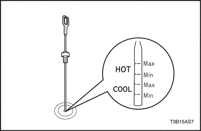
- Remove the transaxle fluid dipstick and check the transaxle fluid level.
- The correct fluid level must be between the HOT MIN and the HOT MAX notches on the dipstick.
- If the fluid level is below the MIN notch, add transaxle fluid through the fluid filler tube and check for leaks in the transaxle.
- If the fluid above the MAX notch, the transaxle is overfilled. Drain some of the fluid through the fluid pan drain plug. Check the transaxle fluid level.
Fluid Drain Procedure
Draining Procedure
- Raise and support the vehicle. Refer to "Vehicle Lifting Procedures," Section 0B, General Information.
- Place a suitable fluid drainage container under the transaxle.
- Remove the fluid drain plug. allow the fluid to drain completely.
- Clean the drain plug threads.
- Install the fluid drain plug.
Tighten
Torque the fluid drain plug to 17 N•m (13 Ib-ft).
Filling Procedure
- Remove the drainage container and lower the vehicle.
- Add three-fourths of the recommended amount of ESSO JWS 3309 or TOTAL-ISU FLUID III G.
- Start the engine and allow it to reach normal operating temperature.
- Shift the gear selector through all positions.
- Check the fluid level and add fluid until the dipstick indicates a safe level.
Locating Fluid Leaks
General Method
- Verify that the material leaking is transaxle fluid.
- Thoroughly clean the suspected leak area.
- Allow the transaxle to reach the normal operating temperature of 176-194°F (80-90°C).
- Park the vehicle over a clean paper or a clean cardboard.
- Turn the engine OFF and look for fluid spots on the paper.
- Make the necessary repairs to correct that leak.
Powder Method
- Thoroughly clean the suspected leak area.
- Apply an aerosol type powder, such as foot powder, to the suspected leak area.
- Allow the transaxle to reach the normal operating temperature of 176-194°F (80-90°C).
- Turn the engine OFF.
- Inspect the suspected leak area and trace the leak path through the powder to find the source of the leak.
- Make the necessary repairs to correct the leak.
Once the leak point is found, the source of the leak must be determined and repaired.
Case Porsity Repair
- Determine the leak area. Refer to "Locating Fluid Leaks"
in this section.
- Clean the leak area with the solvent. Air dry.
Caution : Epoxy cement may cause skin irritations and eye damage. Read and follow all information on the container label as provided by the manufacturer.
- Mix a sufficient amount of epoxy cement following the manufacturer's recommendations.
- While the transaxle case is hot, apply epoxy cement with a clean, dry soldering acid brush.
- Allow the epoxy cement to dry for 3 hours before starting the engine.
Fluid Cooler Flushing
Flushing Procedure
- Drain the fluid from the transaxle and refill the transaxle with new transaxle fluid. Refer to "Fluid Drain Procedure"
in this section.
- Let the engine idle for 5 minutes.
- Drain the fluid from the transaxle and refill the transaxle with new transaxle fluid. Refer to "Fluid Drain Procedure"
in this section.
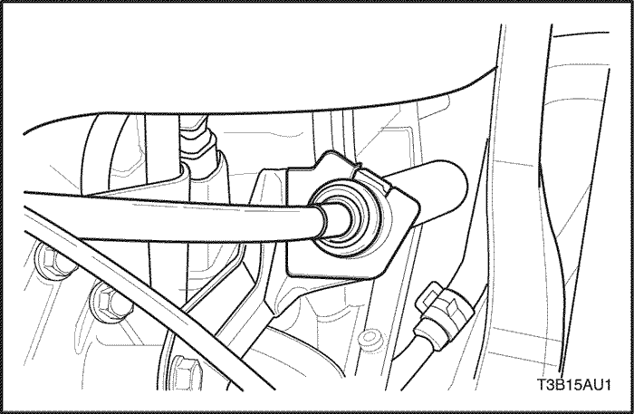
Control Cable Adjustment
Adjustment Procedure
The various shift control cable positions must match at the shift control lever in the vehicle and at the selector lever on the transaxle to provide proper transaxle shifting.
Place the shift control lever in the PARK position and check the selector lever connection to verify that it is in the forward most position. If it is not, the following adjustment must be performed:
- Disconnect the negative battery cable.
- Remove the trim panel from the floor console. Refer to Section 9G, Interior Trim.
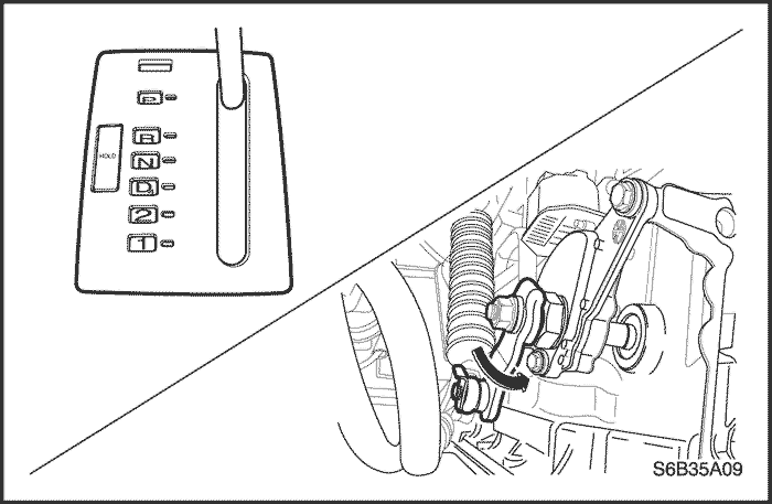
- Place the shift control lever in the PARK position.
- Loosen the control cable adjusting nut.
- Move the TR switch lever counterclockwise until stopping the lever.
- Pull the shift control cable until it is tight and tighten the control cable adjusting nut.
Tighten
Tighten the control cable adjusting nut to 8 N•m (71 Ib-in).
- Install the floor console trim panel. Refer to Section 9G, Interior Trim.
- Connect the negative battery cable.
Shift Control Lever Assembly
Removal Procedure
- Disconnect the negative battery cable.
- Remove the floor console. Refer to Section 9G, Interior Trim.
- Disconnect the wiring harness connectors from the shift control lever.
- Loosen the control cable adjusting nut.
- Disconnect the control cable from the shift control lever assembly.
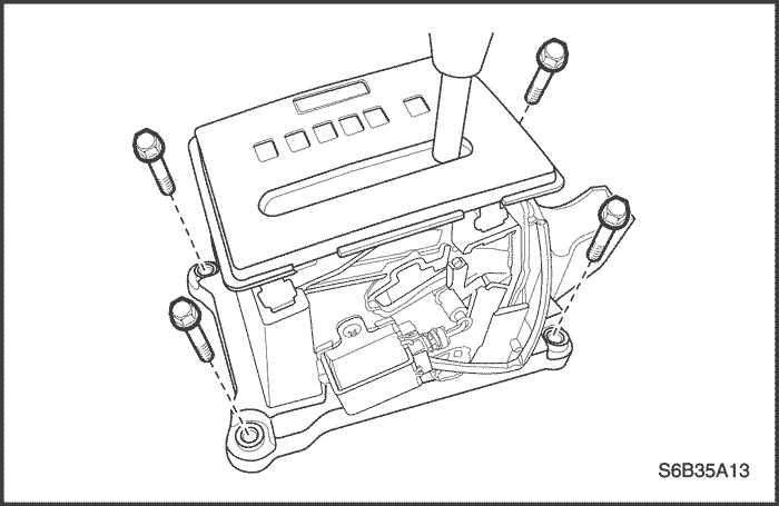
- Remove the shift control lever assembly mounting bolts.
- Remove the shift control lever assembly.
Installation Procedure
- Install the shift control lever assembly and mounting bolts.
Tighten
Tighten the shift control lever assembly mounting bolts to 8 N•m (71 Ib-in).
- Connect the control cable to the shift control lever assembly.
- Tighten the control cable adjusting nut.
Tighten
Tighten the control cable adjusting nut to 8 N•m (71 Ib-in).
- Connect the harness connector.
- Adjust the control cable. Refer to "Control Cable Adjustment"
in this section.
- Install the floor console. Refer to Section 9G, Interior Trim.
- Connect the negative battery cable.
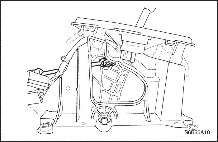
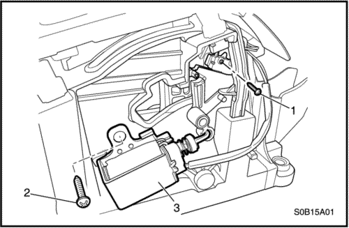
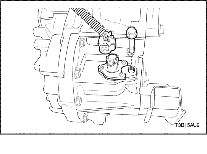
BTSI Solenoid
Removal Procedure
- Disconnect the negative battery cable.
- Remove the shift control lever assembly. Refer to "Shift Control Lever Assembly"
in this section.
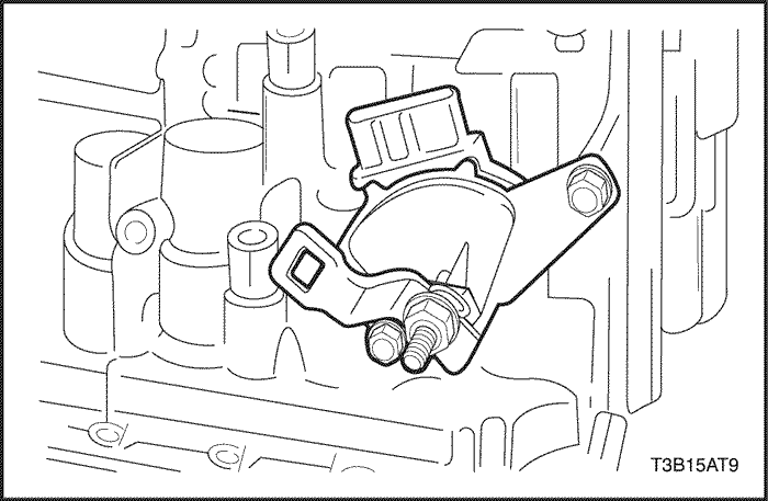
- Disconnect the wiring harness connectors.
- Remove the micro-switch screw(1).
- Remove the BTSI solenoid retaining screw(2).
- Remove the BTSI solenoid(3).
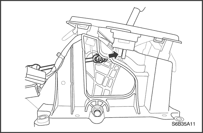
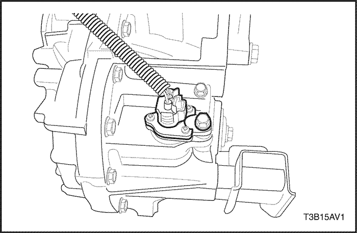
Installation Procedure
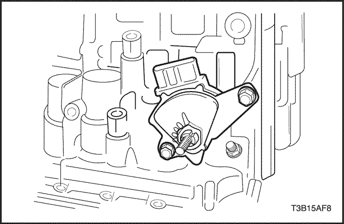
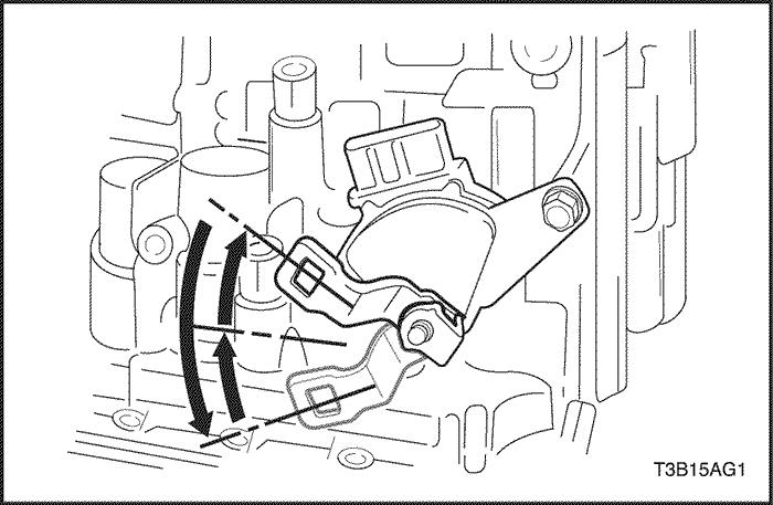
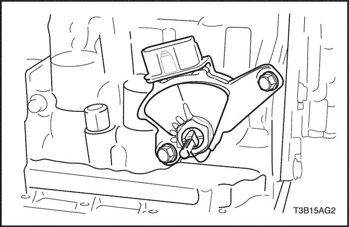
Notice : Make sure that lever of BTSI solenoid is correctly located when installing the solenoid.
Caution : Make sure not to over-tighten the micro-switch retaining screw as thread can be damaged.
- Install the BTSI solenoid(3) with screw(2).
Tighten
Tighten the screw to 2 N•m (18 Ib-in).
- Install the micro-switch screw(1) and tighten it.
- Connect the wiring harness connectors.
- Install the shift control lever assembly. Refer to "Shift Control Lever Assembly"
in this section.
- Connect the negative battery cable.
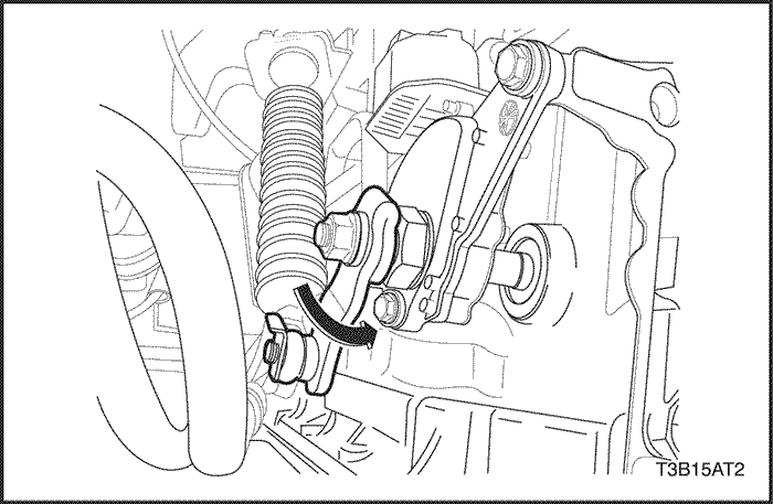
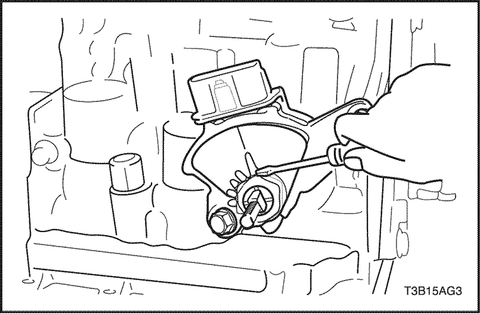
Transmission Range (TR) Switch
Removal Procedure
- Disconnect the negative battery cable.
- Disconnect the TR switch electrical connector from the wiring harness.
- Remove the E-ring.
- Disconnect the shift control cable from the TR switch lever.
- Remove the retaining nut and then remove the washer and the control lever.
- Using a driver, unstake the lock washer and remove the nut.
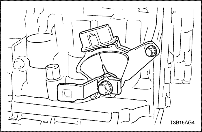
Installation Procedure
- Install the TR switch onto the manual valve lever shaft and temporarily install the 2 adjusting bolts.
- Install the new lock washer and nuts.
Tighten
Tighten the nuts to 12 N•m (106 Ib-in).
- Temporarily install the control lever.
- Turn the lever counterclockwise until it stops, then turn it clockwise 2 notches.
- Remove the control lever.
- Aligh the groove with the neutral basic line, then install the 2 bolts.
Tighten
Tighten the 2 bolts to 5.4 N•m (48 Ib-in).
- Using a screw driver, stake the nut with the lock washer.
- Install the control lever, washer and nut.
Tighten
Tighten the nut to 12 N•m (106 Ib-in).
- Connect the control cable to the TR switch.
- Connect the TR switch electrical connector.
- Adjust the control cable. Refer to "Control Cable Adjustment"
in this section.
- Install the control cable adjusting nut.
Tighten
Tighten the control cable adjusting nut to 8 N•m (71 Ib-in).
- Connect the negative battery cable.
Shift Control Cable
Removal Procedure
- Disconnect the negative battery cable.
- Remove the floor console. Refer to Section 9G, Interior Trim.
- Remove the cable adjusting nut.
- Disconnect the shift control cable from the shift control lever assembly.
- Remove the shift control cable retaining E-ring.
- Disconnect the shift control cable from the TR switch.
- Remove the E-ring from the shift control cable bracket and disconnect the shift control cable.
- Disconnect the shift control cable from the shift control cable fastener.
- Remove the shift control cable from the vehicle.
Installation Procedure
- Install the shift control cable to the vehicle.
- Connect the shift control cable to the shift control cable fastener.
- Install the E-ring to the shift control cable bracket and connect the shift control cable.
- Connect the shift control cable to the TR switch.
- Install the shift control cable retaining E-ring.
- Connect the shift control cable to the shift control lever assembly.
- Install the cable adjusting nut.
Tighten
Tighten the cable adjusting nut to 8 N•m (71 Ib-in).
- Install the trim panel to the floor console. Refer to Section 9G, Interior Trim.
- Connect the negative battery cable.
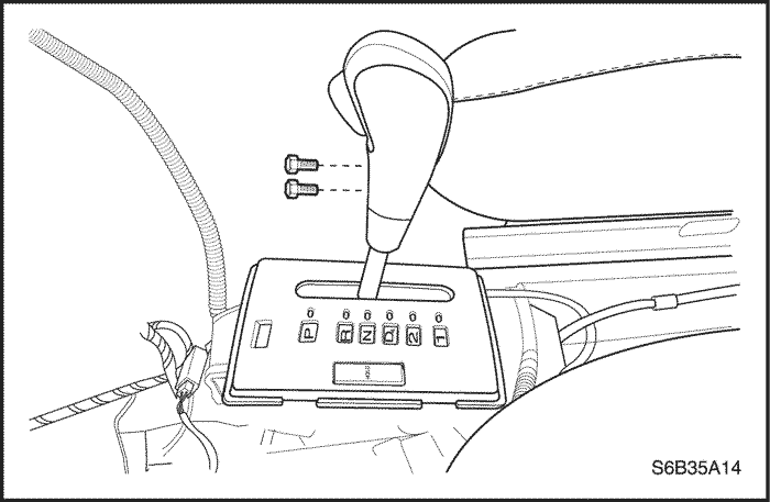
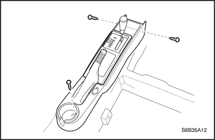
Shift Select Cover
Removal Procedure
- Disconnect the negative battery cable.
- Remove the floor console. Refer to Section 9G, Interior Trim.
- Remove the shift select lever knob bolts and the knob.
- Disconnect the connectors.
- Remove the shift select cover from the shift select housing.
Installation Procedure
- Connect the connectors to the shift select cover.
- Install the shift select cover to the houng.
- Install the shift select lever knob and bolts.
Tighten
Tighten the shift select lever knob bolts to 2 N•m (18 Ib-in).
- Install the floor console. Refer to Section 9G, Interior Trim.
- Connect the negative battery cable.
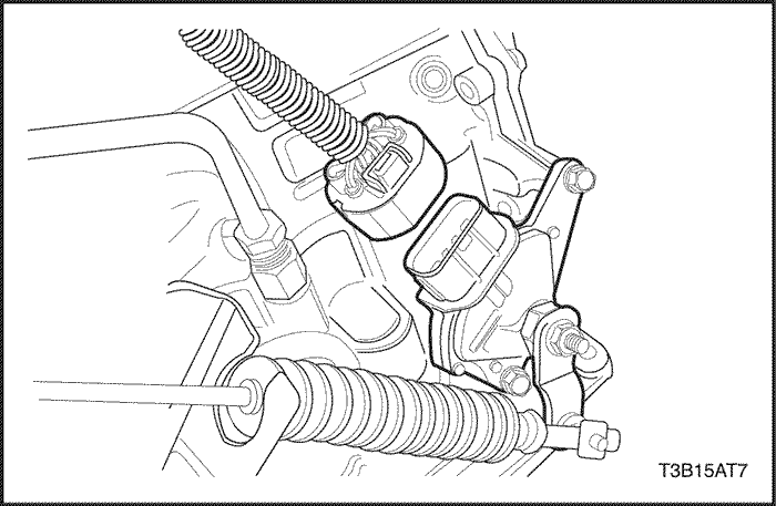
Input Shaft Speed (ISS) Sensor
Removal Procedure
- Disconnect the negative battery cable.
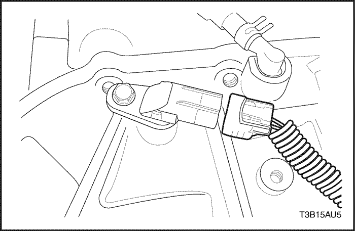
- Disconnect the input shaft speed (ISS) sensor electrical connector.
- Remove the ISS sensor retaining bolt.
- Remove the ISS sensor from the transaxle.
Installation Procedure
Notice : Lubricate the O-ring with ATF.
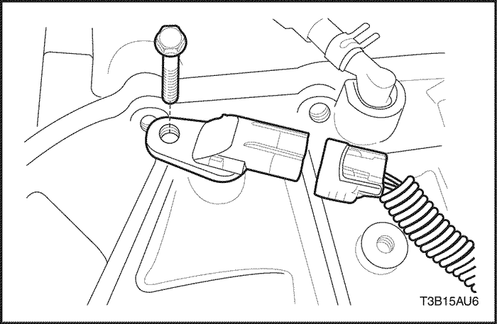
- Install a new O-ring on the ISS sensor.
- Install the ISS sensor and retaining bolt into the transaxle case.
Tighten
Tighten the ISS sensor retaining bolt to 5.4 N•m (48 Ib-in).
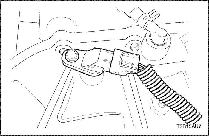
- Connect the ISS sensor electrical connector.
- Connect the negative battery cable.
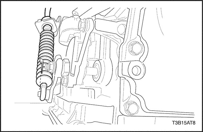
Output Shaft Speed (OSS) Sensor
Removal Procedure
- Disconnect the negative battery cable.
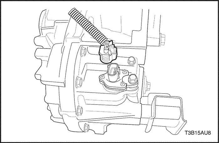
- Disconnect the output shaft speed (OSS) sensor electrical connector.
- Remove the OSS sensor retaining bolt.
- Remove the OSS sensor from the transaxle.
Installation Procedure
Notice : Lubricate the O-ring with ATF.
- Install a new O-ring on the output shaft speed (OSS) sensor.
- Install the OSS sensor and retaining bolt into the transaxle.
Tighten
Tighten the OSS sensor retaining bolt to 7.4 N•m (65 Ib-in).
- Connect the OSS sensor electrical connector.
- Connect the negative battery cable.
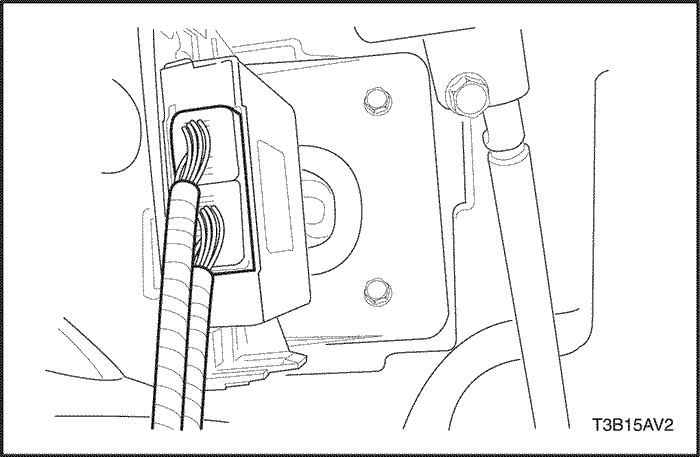
Transmission Control Module (TCM)
Removal Procedure
- Disconnect the negative battery cable.
- Disconnect the transmission control module (TCM) electrical connector.
- Remove the TCM retaining bolts.
- Remove the TCM.
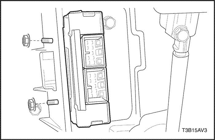
Installation Procedure
- Install the TCM and retaining bolts.
Tighten
Tighten the TCM retaining bolts to 5 N•m (44 Ib-in).
- Connect the TCM electrical connector.
- Connect the negative battery cable.
- Perform the transmission adaptive learn procedure. Refer to "Transmission Adaptive Learn Procedure" in this section.
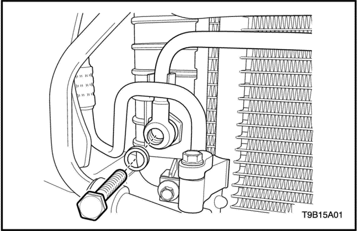
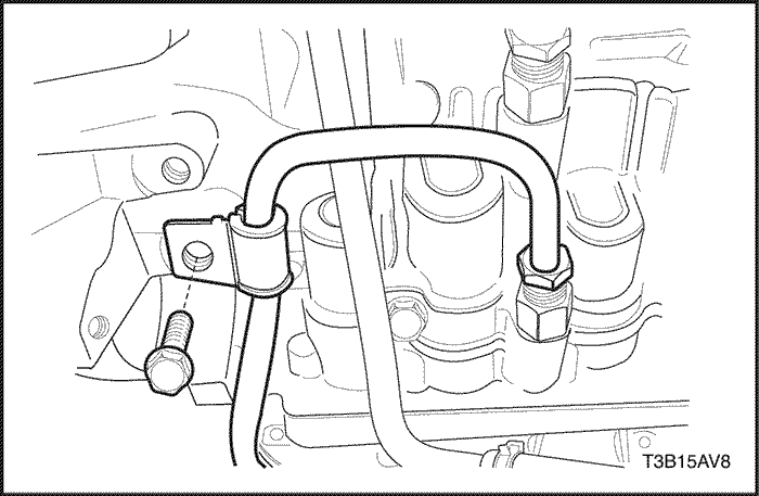
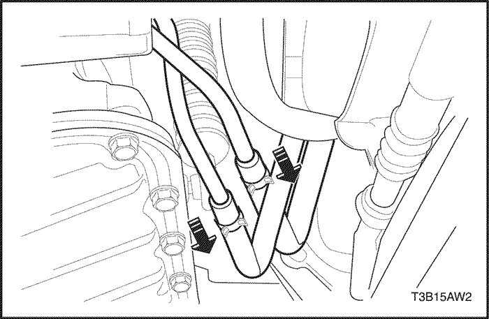
Fluid Cooler Inlet Pipes and Hoses
Removal Procedure
- Raise and support the vehicle.
- Drain the transaxle fluid.
- Remove the inlet pipe union bolt and washers from the radiator.
- Remove the inlet and outlet pipes retaining bolt.
- Remove the fluid cooler inlet pipe clip bolt from the transaxle.
- Remove the inlet pipe fitting nut from the transaxle.
- Remove the fluid cooler inlet pipe and hoses.
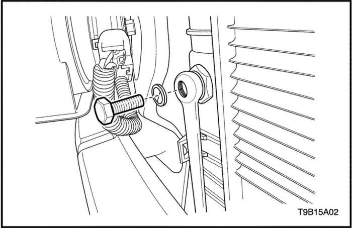
Installation Procedure
- Install the fluid cooler inlet pipe fitting nut into the transaxle.
Tighten
Tighten the fluid cooler inlet pipe fitting nut to 35 N•m (26 Ib-ft).
- Install the fluid cooler inlet pipe clip bolt into the transaxle.
Tighten
Tighten the fluid cooler inlet pipe clip bolt to 9 N•m (80 Ib-in).
- Install the inlet and outlet pipes retaining bolt.
Tighten
Tighten the inlet and outlet pipes retaining bolt to 9 N•m (80 Ib-in).
- Install the inlet pipe union bolt and new washers into the radiator.
Tighten
Tighten the inlet pipe union bolt to 35 N•m (26 Ib-ft).
- Lower the vehicle.
- Fill the transaxle with the fluid.
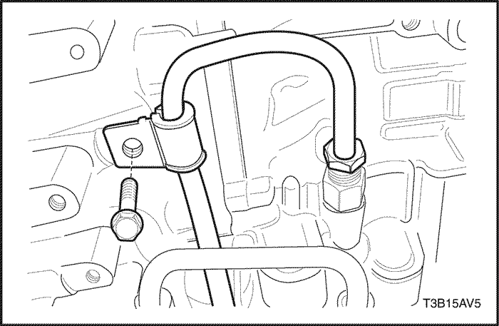
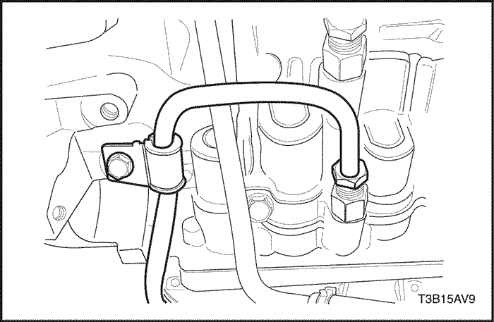
Fluid Cooler Outlet Pipe and Hoses
Removal Procedure
- Drain the transaxle fluid.
- Remove the instrument panel.
- Remove the outlet pipe union bolt and washers from the radiator.
- Remove the inlet and outlet pipes retaining bolt.
- Remove the outlet pipe clip bolt from the transaxle.
- Remove the outlet pipe fitting nut from the transaxle.
- Remove the fluid cooler outlet pipe and hoses.
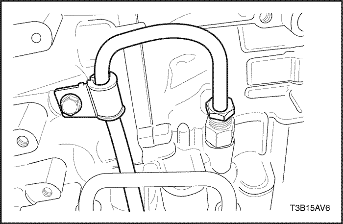
Installation Procedure
- Install the fluid cooler outlet pipe fitting nut.
Tighten
Tighten the fluid cooler outlet pipe fitting nut to 35 N•m (26 Ib-ft).
- Install the fluid cooler outlet pipe clip bolt.
Tighten
Tighten the fluid cooler outlet pipe clip bolt to 9 N•m (80 Ib-in).
- Install the inlet and outlet pipes retaining bolt.
Tighten
Tighten the inlet and outlet pipes retaining bolt to 9 N•m (80 Ib-in).
- Install the outlet pipe union bolt and new washers into the radiator.
Tighten
Tighten the outlet pipe union bolt to 35 N•m (26 Ib-ft).
- Install the instrument panel.
- Fill the transaxle with the fluid.
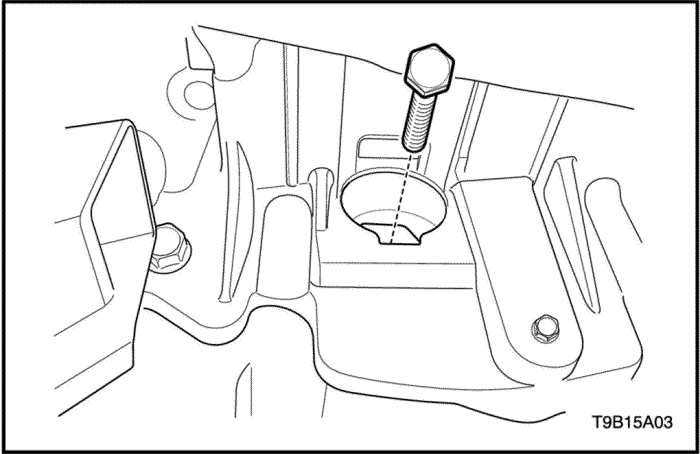
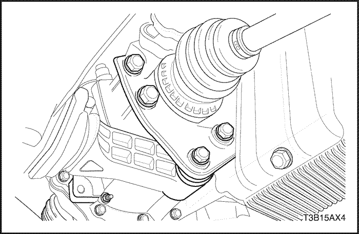
Left Transaxle Bracket and Mount
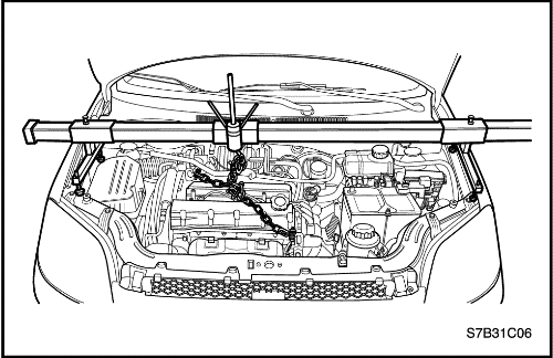
Tools Required
EN-48356 Engine Fixture or equivalent
Removal Procedure
- Remove the battery and battery tray. Refer to Section 1E, Engine Electrical.
- Install the engine fixture EN-48356 or equivalent.
- Support the transaxle with a supporting jack.
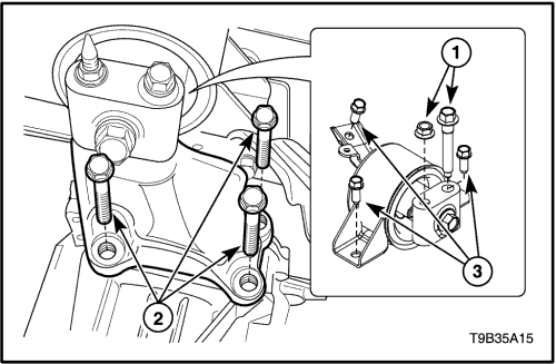
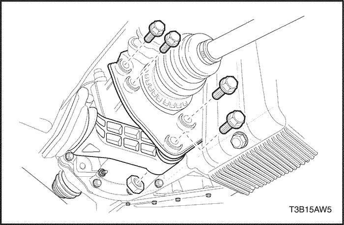
- Remove the left transaxle mounting bracket cage bolt and nut(1).
- Remove the left transaxle mounting bracket bolts(2).
- Remove the left transaxle mounting bracket from the transaxle mount.
- Remove the left transaxle mount to body bolts(3) and the mount.
Installation Procedure
- Install the left transaxle mount to the vehicle.
- Install the transaxle mount to body bolts(3).
Tighten
Tighten the transaxle mount to body bolts(3) to 55 N•m (41 Ib-ft).
- Install the left transaxle mounting bracket and the bracket bolts(2).
Tighten
Tighten the transaxle mounting bracket bolts(2) to 60 N•m (44 Ib-ft).
- Install the transaxle mounting bracket cage bolt and nut(1).
Tighten
Tighten the transaxle mounting bracket cage bolt and nut(1) to 95 N•m (70 Ib-ft).
- Remove the supporting jack and engine fixture EN-48356 or equivalent.
- Install battery and battery tray. Refer to Section 1E, Engine Electrical.
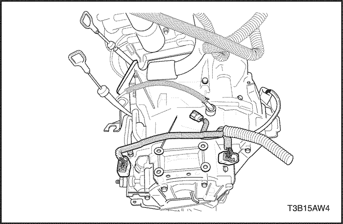
Transaxle Assembly
Tools Required
EN-48356 Engine Fixture
DW260-012 Transaxle Support Fixture (81-40 LE)
Removal Procedure
- Remove the battery and battery tray. Refer to Section 1E, Engine Electrical
- Drain the transaxle fluid. Refer to "Fluid Drain Procedure"
in this section.
- Remove the left and right drive axle assemblies. Refer to Section 3A, Automatic Transaxle Drive Axle.
- Disconnect the fluid cooler inlet and outlet hoses from the transaxle.
- Disconnect the shift control cable from the transaxle. Refer to "Shift Control Cable"
in this section.
- Install engine fixture EN-48356 to support the engine.
- Disconnect the input shaft speed (ISS) sensor electrical connector.
- Disconnect the output shaft speed (OSS) sensor electrical connector.
- Disconnect the TR switch electrical connector.
- Disconnect the transaxle electrical connector.
- Remove the service hall cover.
- Remove the torque converter bolts.
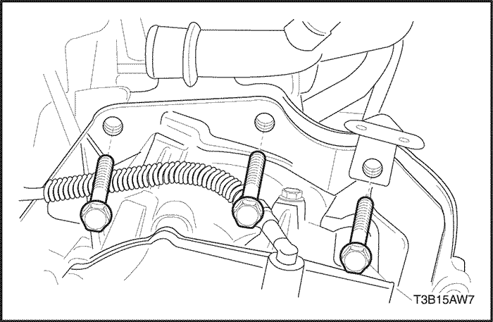
- Remove the damping block connection nut and bolt.
- Remove the rear mounting bracket bolts and rear mounting bracket.
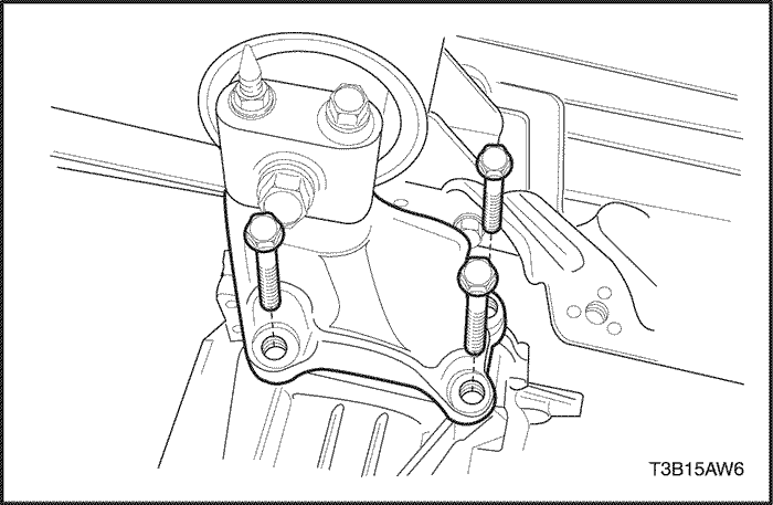
- Remove the three upper transaxle mounting bracket bolts.
- Remove the three upper transaxle-to-engine mounting bolts.
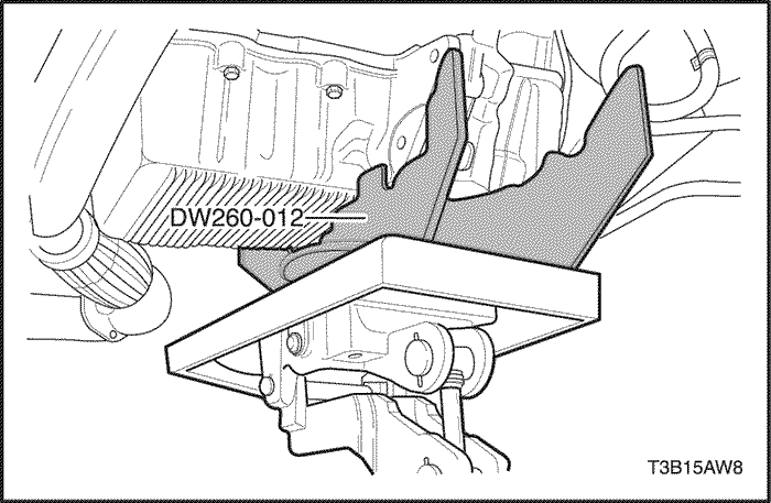
- Secure the transaxle to a transaxle jack and transaxle support fixture DW260-012 (81-40 LE).
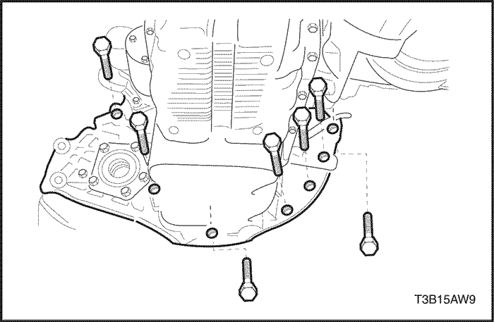
- Remove the seven lower transaxle-to-engine retaining bolts.
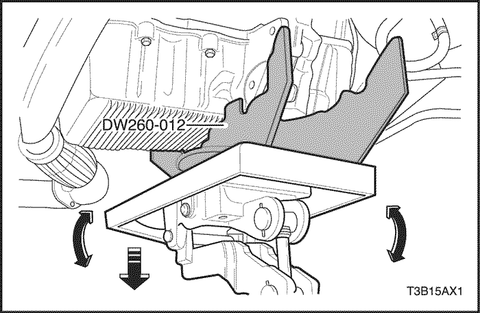
- Carefully remove the transaxle from the vehicle.
Installation Procedure
- Secure the transaxle to the transaxle jack, then carefully position in the vehicle.
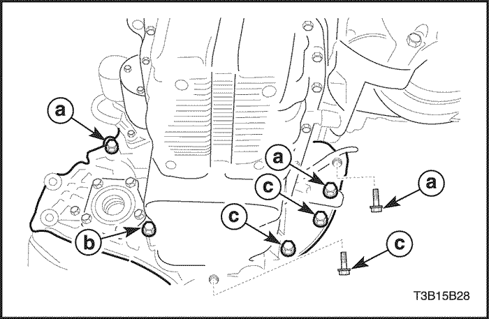
- Install the seven lower transaxle-to-engine retaining bolts.
Tighten
Tighten the bolts(a) to 75 N•m (55 Ib-ft).
Tighten
Tighten the bolts(b) to 20 N•m (15 Ib-ft).
Tighten
Tighten the bolts(c) to 30 N•m (22 Ib-ft).
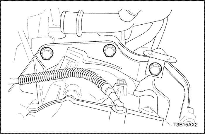
- Install the three upper transaxle-to-engine mounting bolts.
Tighten
Tighten the three upper transaxle-to-engine mounting bolts to 75 N•m (55 Ib-ft).
- Install the three upper transaxle mounting bracket bolts and the bracket.
Tighten
Tighten the three upper transaxle mounting bracket bolts to 60 N•m (44 Ib-ft).
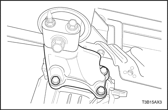
- Install the rear mounting bracket bolts and the bracket.
Tighten
Tighten the rear mounting bracket bolts to 60 N•m (44 Ib-ft).
- Install the damping block connection nut and bolt.
Tighten
Tighten the damping block connection nut and bolt to 85 N•m (63 Ib-ft).
- Install the torque converter bolts.
Tighten
Tighten the torque converter bolts to 45 N•m (33 Ib-ft).
- Install the service hall cover.
- Connect the transaxle electrical connector.
- Connect the TR switch electrical connector.
- Connect the OSS sensor electrical connector.
- Connect the ISS sensor electrical connector.
- Remove engine fixture EN-48356.
- Connect the shift control cable into the transaxle. Refer to "Shift Control Cable"
in this section.
- Connect the fluid cooler inlet and outlet hose into the transaxle.
- Install the left and right drive axle assemblies. Refer to Section 3A, Automatic Transaxle Drive Axle.
- Install the battery and battery tray. Refer to Section 1E, Engine Electrical.
- Fill the transaxle with fluid. Refer to "Fluid Drain Procedure"
in this section.
- Check the fluid level. Refer to "Transaxle Fluid Level Checking Procedure"
in this section.
- Perform the transmission adaptive learn procedure. Refer to "Transmission Adaptive Learn Procedure" in this section.
 |
|
 |
|
| © Copyright Chevrolet Europe. All rights reserved |


