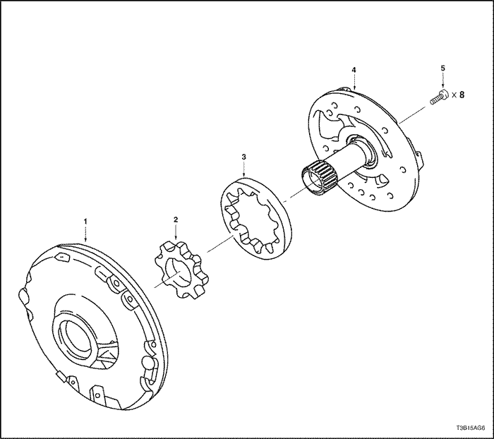
Oil Pump
- Oil Pump Body
- Oil Pump Drive Gear
- Oil Pump Driven Gear
- Stator Shaft
- Bolt
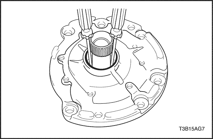


Disassembly Procedure
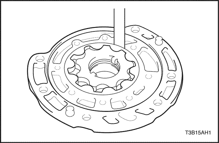
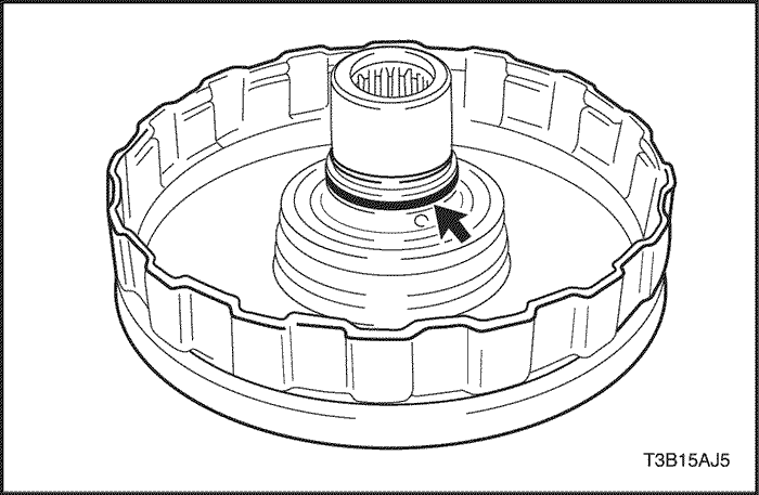
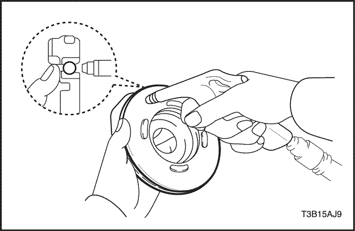
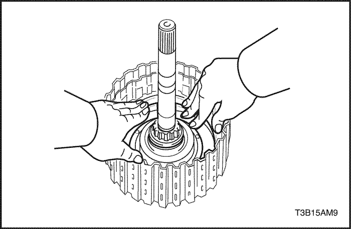
- Turn the drive gear with 2 screwdrivers and make sure it rotates smoothly.
Notice : Be careful not to damage the oil lip.
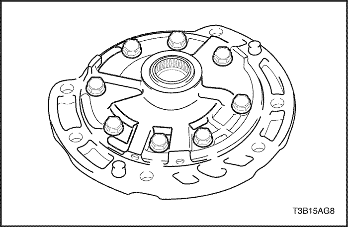
- Remove the 8 bolts and stator shaft.
Notice : Be careful not to let the driver drop as it might come off attached to the stator shaft.
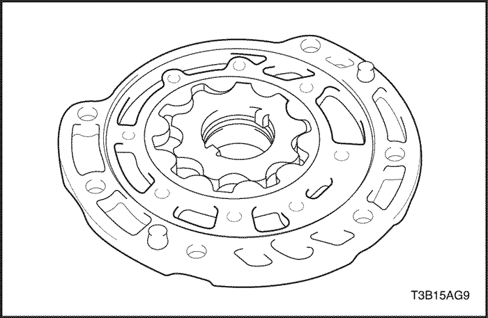
- Remove the oil pump drive gear and driven gear from the oil pump body.
Inspection Procedure
- Push the driven gear to one of side of the body. Using a feeler gauge, measure the clearance.
-
- 0.10 – 0.17 mm (0.0039 – 0.0067 in.)
- Maximum body clearance: 0.17 mm (0.0067 in.)
-
- If the body clearance is greater than the maximum, replace the oil pump body sub-assembly.
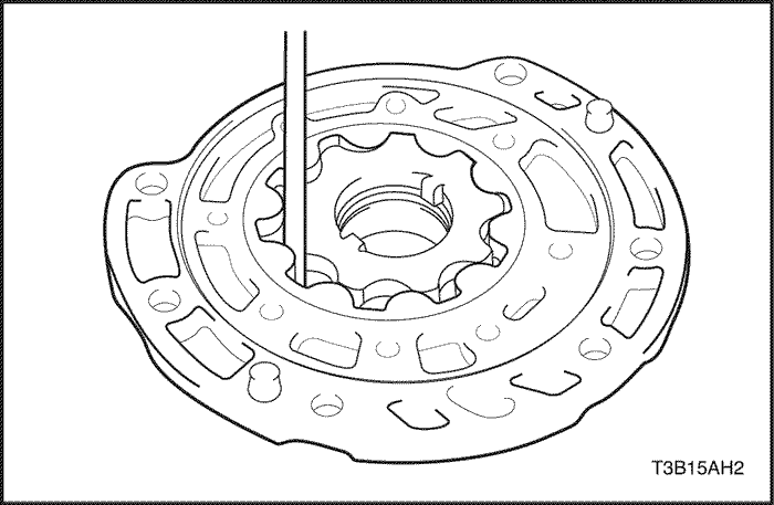
- Measure the tip clearance between the driven gear teeth and drive gear teeth.
-
- 0.07 – 0.15 mm (0.0028 – 0.0059 in.)
- Maximum tip clearance: 0.15 mm (0.0059 in.)
-
- If the tip clearance is greater than the maximum, replace the oil pump body sub-assembly.
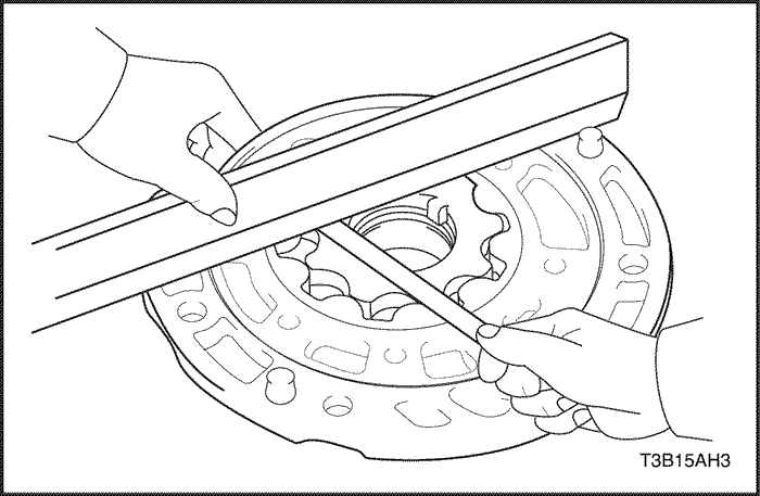
- Using a steel straight edge and feeler gauge, measure the side clearance of both gears.
-
- 0.02 – 0.05 mm (0.0008 – 0.0020 in.)
- Maximum side clearance: 0.05 mm (0.0020 in.)
-
- If the side clearance is greater than the maximum, replace the drive gear, driven gear or pump body.
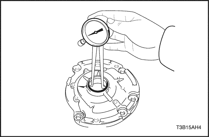
- Using a dial indicator, measure the inside diameter of the oil pump body bushing.
- Standard inside diameter: 38.126 mm (1.50102 in.)
- Maximum inside diameter: 38.188 mm (1.50346 in.)
-
- If the inside diameter is greater than the maximum, replace the oil pump body sub-assembly.
- Using a dial indicator, measure the inside diameter of the stator shaft bushings.
- Standard inside diameter: 18.437 mm (0.72586 in.)
- Maximum inside diameter: 18.5 mm (0.728 in.)
-
- If the inside diameter is greater than the maximum, replace the stator shaft.
Assembly Procedure
- Install the oil pump drive gear and driven gear.
- Align the stator shaft with each bolt hole.
- Install the 8 bolts.
Tighten
Tighten the bolts to 9.8 N•m (87 lb-in).
- Turn the drive gear with 2 screwdrivers and make sure it rotates smoothly.
Notice : Be careful not to damage the oil lip.
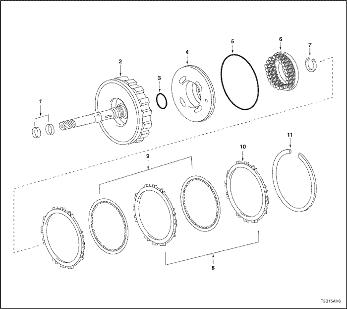
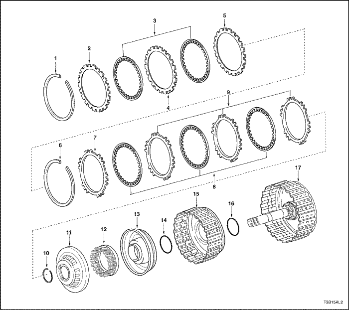
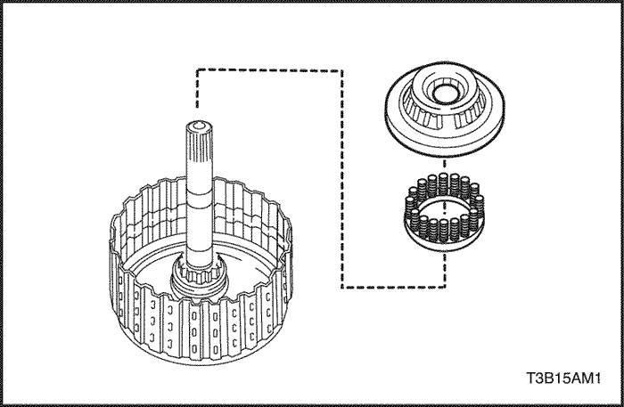
Direct Clutch
- Seal Ring
- Input Shaft Sub-assembly
- O-Ring
- Piston
- O-Ring
- Return Spring
- Snap Ring
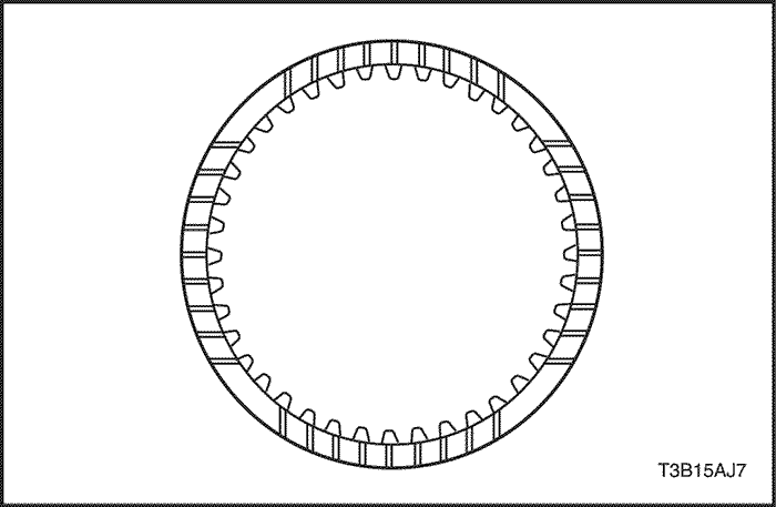
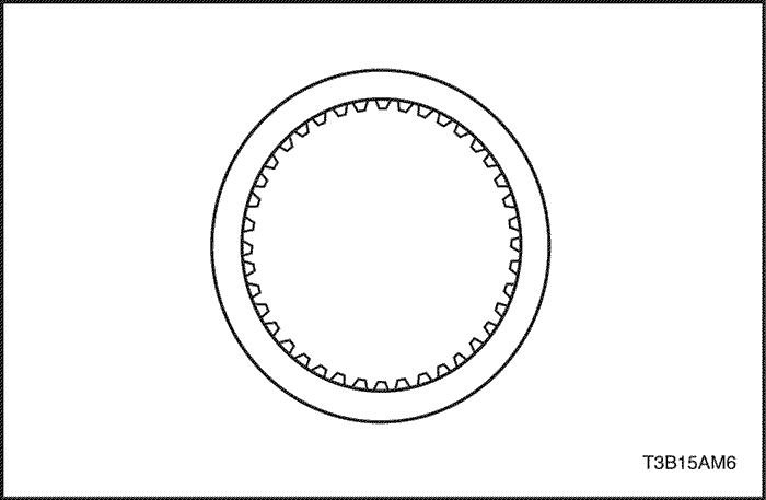
- Plate
- Disc
- Flange
- Snap Ring
Tools Required
DW240-020 Brake/Clutch Spring Compressor
DW240-040 Direct Clutch Adapter
Disassembly Procedure
USE CAUTION WHEN CHECKING COMPONENTS WITH COMPRESSED AIR OR PERSONAL INJURY MAY RESULT.
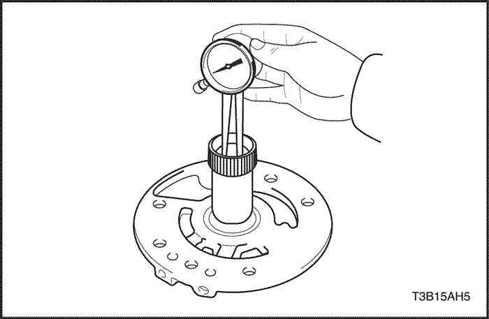
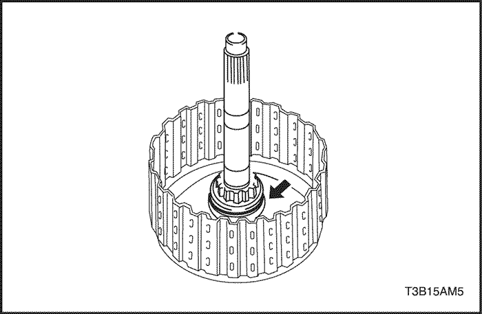
- Install the direct clutch and thrust needle roller bearing on the oil pump.
- Using a dial indicator, measure the direct clutch piston stroke while applying and releasing 392 kPa (57 psi).of compressed air.
-
- Piston stroke: 0.4 – 0.8 mm (0.016 – 0.031 in.)
- If the stroke is non-standard, inspect the discs, plates and flange.
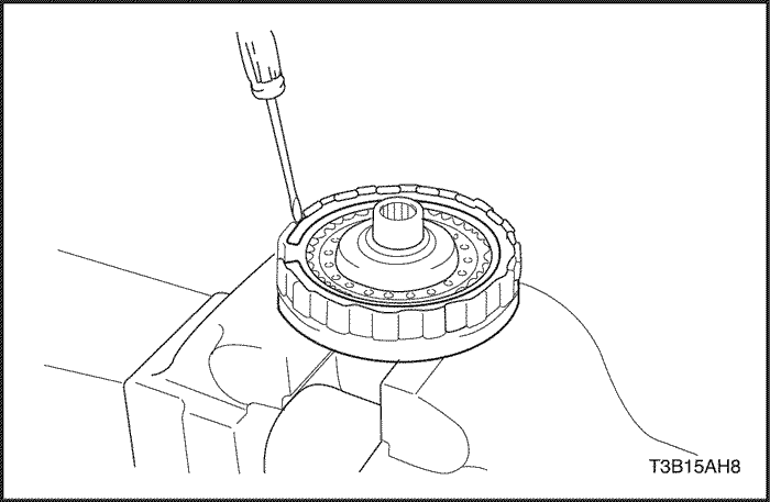
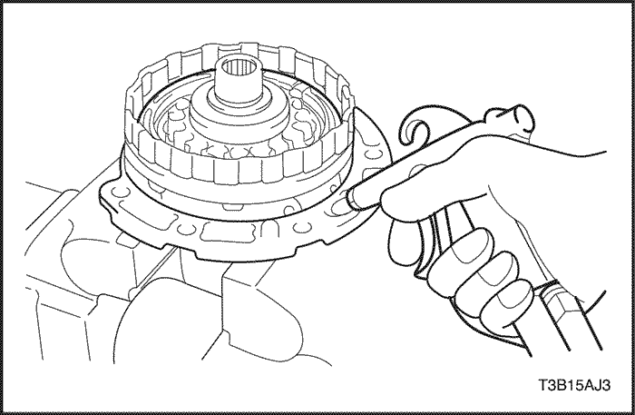
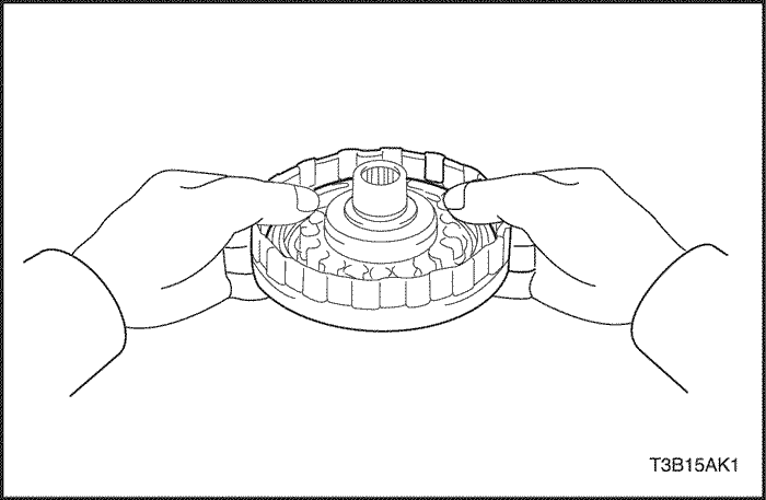
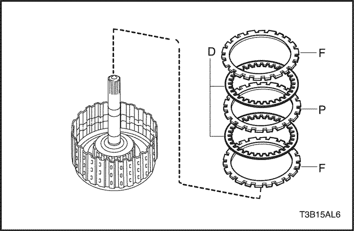
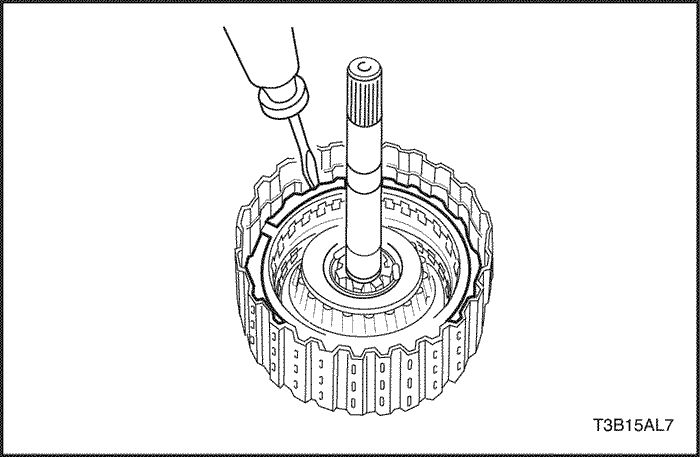
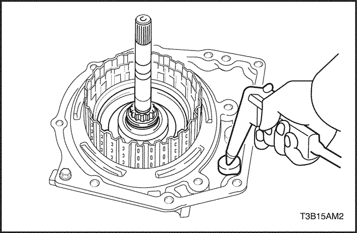
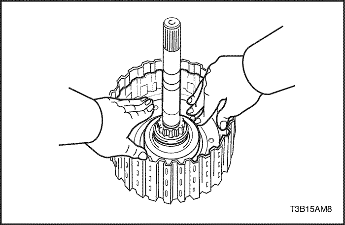
- Using a screwdriver, remove the snap ring.
- Remove the flange, 2discs and 2 plates.
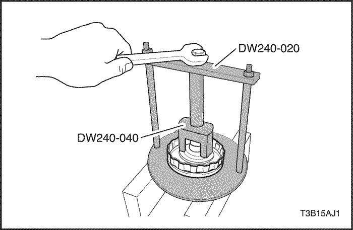
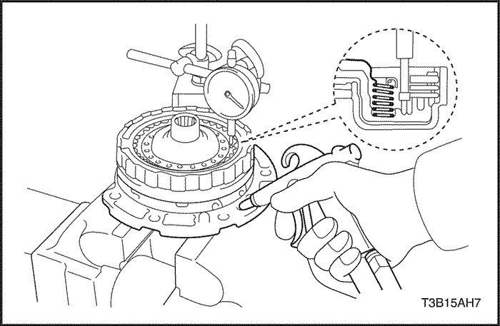
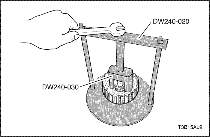
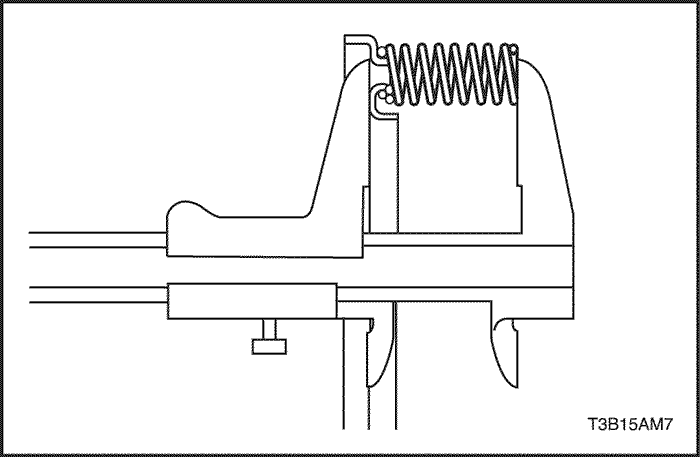
- Place the brake/clutch spring compressor DW240-020 and direct clutch adapter DW240-040 on the direct clutch return spring and compress.
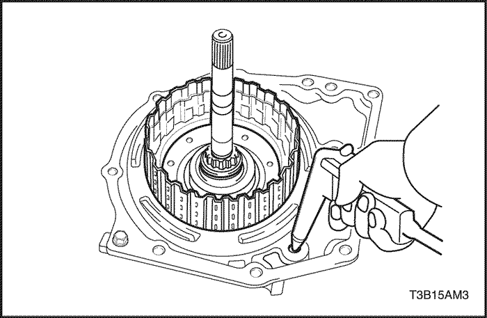
- Using a snap ring expander, remove the snap ring.
Notice : Stop the press when the piston return spring is lowered to the place 1-2 mm (0.039-0.078 in.) from the snap ring groove, preventing the piston return spring from being deformed.
Notice : Do not expand the snap ring excessively.
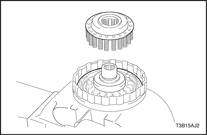
- Remove the direct clutch return spring.
- Install the direct clutch on the oil pump.
USE CAUTION WHEN REMOVING COMPONENTS WITH COMPRESSED AIR OR PERSONAL INJURY MAY RESULT.
Notice : Blowing off the air may cause the piston'jump-out.When removing the piston, hold it with your hand using a waste cloth.
Notice : Take care not to splash ATF when air-blowing.
- Apply 392 kPa (57 psi) of compressed air to the oil pump to remove the direct clutch piston.
- When the piston can not be removed as it is slanted, either blow the air again with the protruding side pushed or remove the piston using needle nose pliers with vinyl tape on the tip.
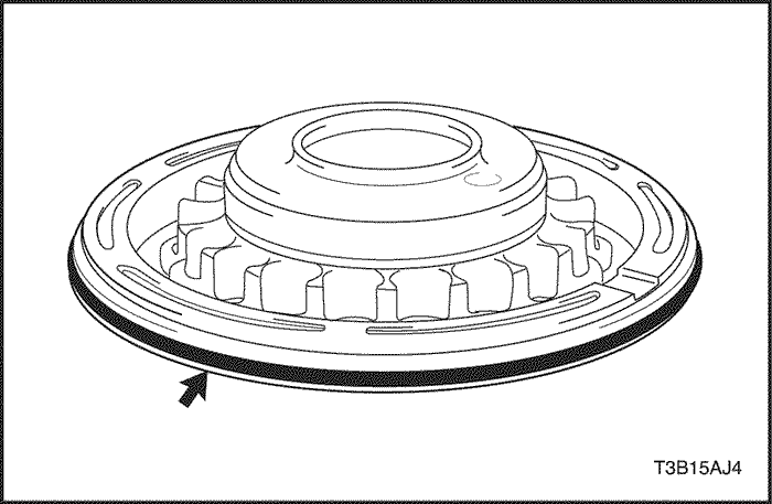
- Using a small screwdriver, remove the O-ring from the direct clutch piston.
- Remove the O-ring from the input shaft.
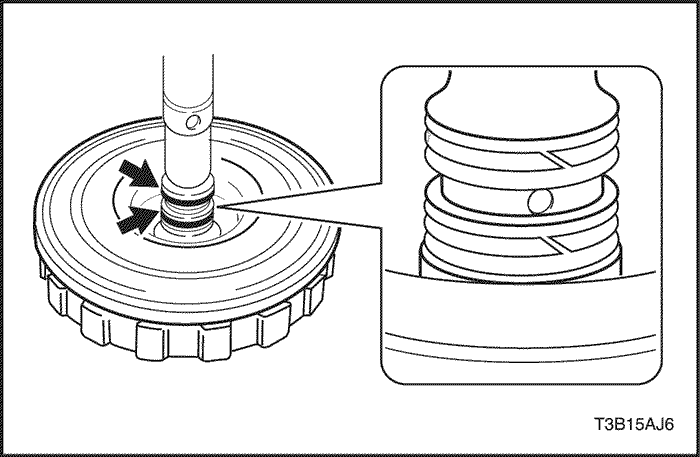
- Remove the 2 seal rings from the input shaft.
Notice : Do not expand the ring ends excessively.
Inspection Procedure
- Check to see if the sliding surface of the disc, plate and flange are worm or burnt. If necessary, replace them.
- If the lining of the disc is peeling off or discolored, or even if a part of the printed number is defaced, replace all discs.
- Before assembling new discs, soak them in ATF for at least 15 minutes.
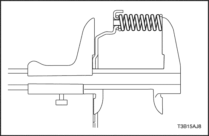
- Using vernier calipers, measure the free length of the direct clutch return spring together with the spring sheet.
- Standard free length: 36.04 mm (1.4189 in.)
- Check that the check ball is free by shaking the direct clutch piston.
- Check that the valve does not leak by applying low-pressure compressed air.
Assembly Procedure
- Install the 2 seal rings to the input shaft.
Notice : Do not expand the ring ends excessively.
- Coat a new O-ring with ATF and install the O-ring to the input shaft.
- Coat a new O-ring with ATF and install the O-ring to the direct clutch piston.
- Coat the direct clutch piston with ATF, install it to the direct clutch drum.
Notice : Be careful not to damage the lip seal of direct clutch piston.
- Install the direct clutch return spring.
- Place brake/clutch spring compressor DW240-020 and direct clutch adapter DW240-040 on the return spring and compress.
- Using a snap ring expander, install the snap ring.
Notice : Stop the press when the piston return spring is lowered to the place 1-2 mm (0.039-0.078 in.) from the snap ring groove, preventing the piston return spring from being deformed.
Notice : Do not expand the snap ring excessively.
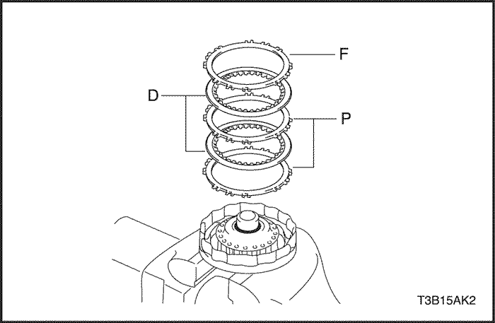
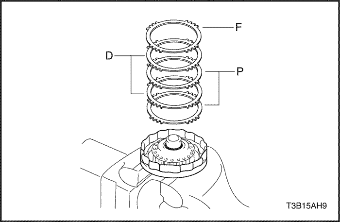
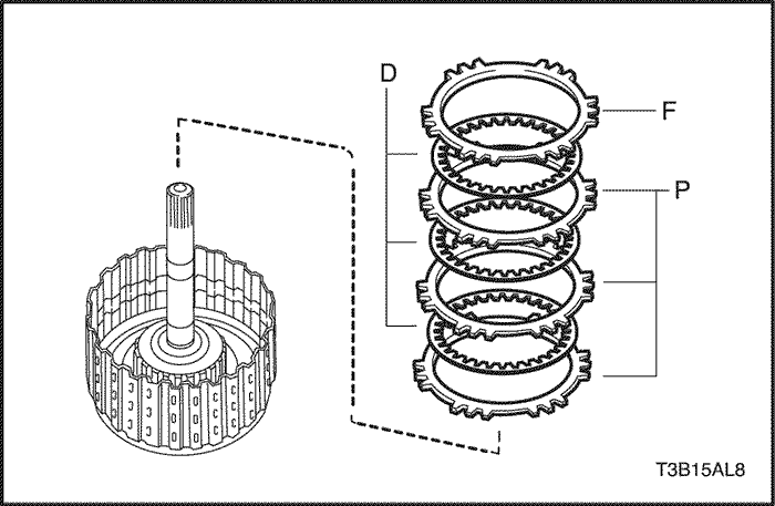
- Install the 2 plates, 2 discs and flange.
- Before installing the discs, coat them with ATF.Install in order: P – D – P – D - F
-
- (P = Plate, D = Disc, F = Flange)
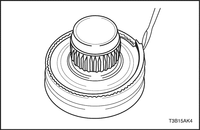
- Using a screwdriver, remove the snap ring.
- Using a screwdriver, remove the snap ring.
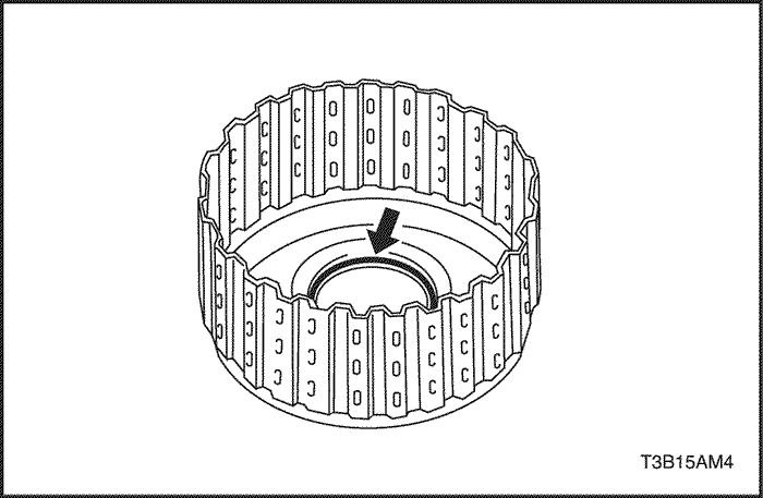
- Check that end gap of the snap ring is not aligned with one of the cutouts.
- Install the direct clutch on the oil pump.
USE CAUTION WHEN CHECKING COMPONENTS WITH COMPRESSED AIR OR PERSONAL INJURY MAY RESULT.
- Using a dial indicator, measure the direct clutch piston stroke while applying and releasing 392 kPa (57 psi) .of compressed air .
-
- Piston stroke: 0.4 – 0.8 mm (0.016 – 0.031 in.)
- If the piston stroke is less than the limit of piston stroke, parts may have been assembled incorrectly, so check and reassemble again.
- If the stroke is non-standard, select another flange.
- There are 3 flanges in different thickness.
- Flange Thickness: mm (in.)
No
|
Thickness
|
No
|
Thickness
|
|
1
|
3.0 (0.118)
|
3
|
3.4 (0.134)
|
|
2
|
3.2 (0.126)
|
.
|
.
|
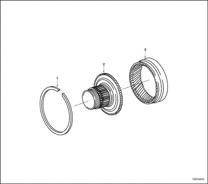
Planetary Ring Gear
- Snap Ring
- Planetary Ring Gear Flange
- Planetary Ring Gear
Disassembly Procedure
- Using a screwdriver, remove the snap ring.
- Remove the planetary ring gear flange from the planetary ring gear.
Assembly Procedure
- Install a new planetary ring gear flange to the planetary ring gear.
- Using a screwdriver, install the snap ring.
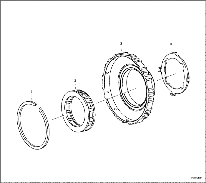
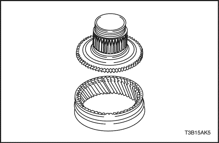
One-Way Clutch
- Snap Ring
- One-Way Clutch
- 2nd Brake Hub
- Retainer
Disassembly Procedure
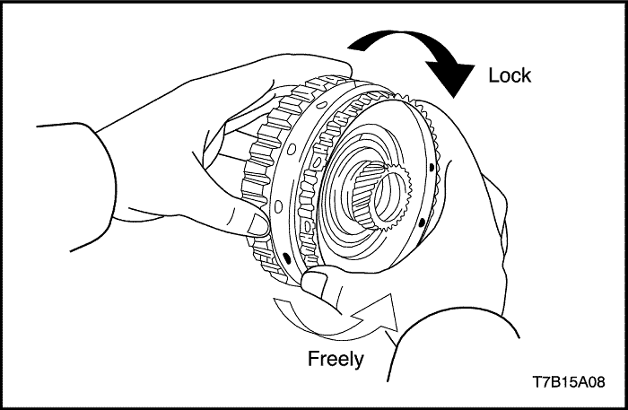
- Install the one-way clutch and thrust washer to the rear planetary sun gear.
- Hold the rear planetary sun gear and turn the one-way clutch. The one-way clutch should turn freely counterclockwise and should lock clockwise.
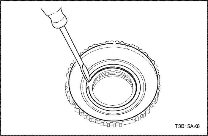
- Using a screwdriver, remove the snap ring from the 2nd brake hub.
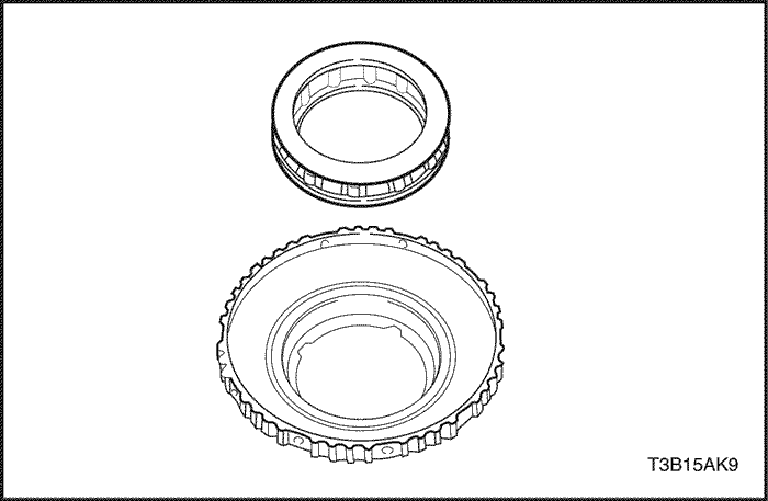
- Remove the one-way clutch from the 2nd brake hub.
- Using a small screwdriver, remove the retainer from the 2nd brake hub.
Assembly Procedure
- Install the retainer to the 2nd brake hub.
- Install the one-way clutch.
- Using a screwdriver, install the snap ring.
- Install the one-way clutch and thrust washer to the rear planetary sun gear.
- Hold the rear planetary sun gear and turn the one-way clutch. The one-way clutch should turn freely counterclockwise and should lock clockwise.
Forward and Reverse Clutch
- Seal Ring
- Flange
- Disc
- Plate
- Flange
- Snap Ring
- Flange
- Disc
- Plate
- Snap Ring
- Clutch Balancer
- Forward Clutch Retrun Spring
- Forward Clutch Piston
- O-Ring
- Forward Clutch Drum
- O-Ring
- Intermediate Shaft Sub-assembly
Tools Required
DW240-020 Brake/Clutch Spring Compressor
DW240-030 Forward Clutch Adapter
DW240-120 Measuring Terminal
Disassembly Procedure
USE CAUTION WHEN CHECKING COMPONENTS WITH COMPRESSED AIR OR PERSONAL INJURY MAY RESULT.
- Install the forward and reverse clutch and thrust needle roller bearing on the transaxle rear cover.
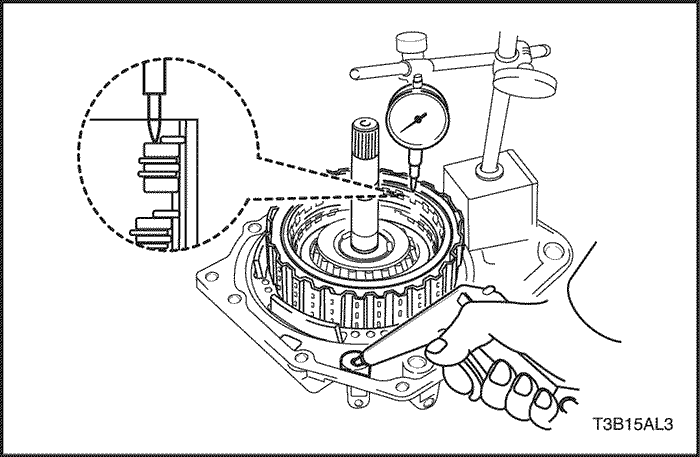
- Using a dial indicator, measure the reverse clutch pack clearance while applying and releasing 392 kPa (57 psi) of compressed air.
- Pack clearance: 0.40 – 1.00 mm (0.0157 – 0.0394 in.)
- If the stroke is non-standard, inspect the discs, plates and flange.
USE CAUTION WHEN CHECKING COMPONENTS WITH COMPRESSED AIR OR PERSONAL INJURY MAY RESULT.
- Install the forward and reverse clutch and thrust needle roller bearing on the transaxle rear cover.
- Install the forward and reverse clutch and thrust needle roller bearing on the transaxle rear cover.
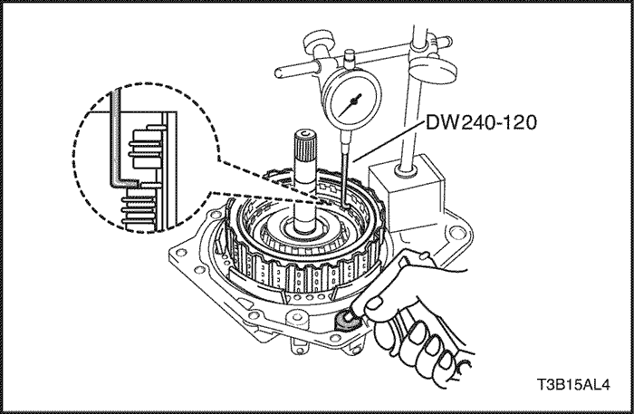
- Using a dial indicator and measuring terminal DW240-120, measure the forward clutch pack clearance while applying and releasing 392 kPa (57 psi). of compressed air.
- The forward and reverse clutch will come out as you apply the compressed air. Therefore, while the checking is being done, press on the input shaft of the forward and reverse clutch using stamping machine or alike so that the pressure is not applied on the forward and reverse clutch.
- Pack clearance: 1.1-1.5 mm (0.043 – 0.059 in.)
-
- If the stroke is non-standard, inspect the discs, plates and flange.
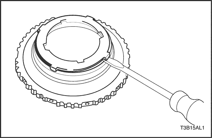
- Using a screwdriver, remove the reverse clutch snap ring.
- Remove the 2 flanges, 2 discs and plate from the reverse clutch drum.
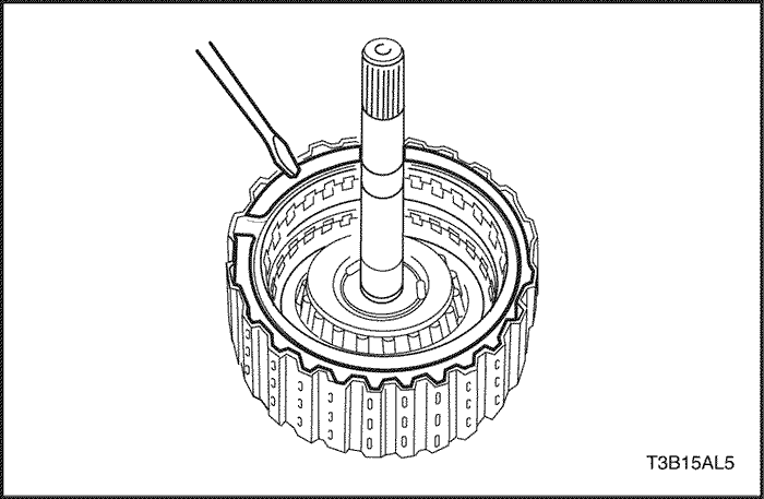
- Using a screwdriver, remove the snap ring.
- Remove the flange, 3 discs and 3 plates from the forward clutch drum.
- Using brake/clutch spring compressor DW240-020 and forward clutch adapter DW240-030, compress the spring.
- Using a snap ring expander, remove the snap ring.
Notice : Stop the press when the clutch balancer is lowered to the place 1-2 mm (0.039-0.078 in.) from the snap ring groove, preventing the clutch balancer from being deformed.
Notice : Do not expand the snap ring excessively.
- Remove the clutch balancer and forward clutch return spring.
USE CAUTION WHEN REMOVING COMPONENTS WITH COMPRESSED AIR OR PERSONAL INJURY MAY RESULT.
- Install the forward and reverse multiple disc clutch on the transaxle rear cover.
- Apply 392 kPa (57 psi) of compressed air to the transaxle rear cover to remove the forward clutch piston.
Notice : Blowing off the air may cause the piston's jump-out.When removing the piston, hold it with your hand using a waste cloth.
Notice : Take care not to splash ATF when air-blowing.
- When the piston can not be removed as it is slanted, either blow the air again with the protruding side pushed or remove the piston using a needle nose pliers with vinyl tape on the tip.
USE CAUTION WHEN REMOVING COMPONENTS WITH COMPRESSED AIR OR PERSONAL INJURY MAY RESULT.
- Apply 392 kPa (57 psi) of compressed air to the transaxle rear cover to remove the forward clutch drum.
Notice : Blowing off the air may cause the drum's jump-out. When removing the drum, hold it with your hand using a waste cloth.
Notice : Take care not to splash ATF when air-blowing.
- When the drum can not be removed as it is slanted, either blow the air again with the protruding side pushed or remove the drum using a needle nose pliers with vinyl tape on the tip.
- Using a small screwdriver, remove the O-ring from the forward clutch drum.
- Using a small screwdriver, remove the O-ring from the intermediate shaft sub-assembly.
Inspection Procedure
- Check to see if the sliding surface of the disc, plate flange are worn or burnt. If necessary, replace them.
- If the lining of the disc is peeling off or discolored, or even if a part of the printed number is defaced, replace all discs.
- Before assembling new discs, soak them in ATF for at least 15 minutes.
- Using vernier calipers, measure the free length of the spring together with the spring seat.
- Standard free length: 24.04 mm (0.9465 in.)
Assembly Procedure
- Coat a new O-ring with ATF, and install it to the intermediate shaft sub-assembly.
- Coat a new O-ring with ATF, and install it to the forward clutch drum.
- Coat the forward clutch drum with ATF, install the forward clutch drum.
Notice : Be careful not to damage the O-ring and lip seal of forward clutch drum.
- Coat the forward clutch piston with ATF, install the forward clutch piston.
Notice : Be careful not to damage the lip seal of forward clutch piston.
- Install the forward clutch return spring and clutch balancer.
Notice : Be careful not to damage the lip seal of forward clutch return spring.
- Place brake/clutch spring compressor DW240-020 and forward clutch adapter DW240-030 on the clutch balancer and compress the piston return spring.
- Using a snap ring expander, install the snap ring.
Notice : Stop the press when the clutch balancer is lowered to the place 1-2 mm (0.039-0.078 in.) from the snap ring groove, preventing the clutch balancer from being deformed.
Notice : Do not expand the snap ring excessively.
- Install the 3 plates, 3 discs and flange.
- Install in order: P – D – P – D – P – D - F
-
- (P = Plate, D = Disc, F = Flange)
- Using a screwdriver, install the snap ring.
- Check that the end gap of the snap ring is not aligned with one of the cutouts.
- Install the plate, 2 discs and 2 flanges.
- Install in order: F – D – P – D - F
-
- (P = Plate, D = Disc, F = Flange)
- Using a screwdriver, install the snap ring.
- Check that the end gap of the snap ring is not aligned with one of the cutouts.
USE CAUTION WHEN CHECKING COMPONENTS WITH COMPRESSED AIR OR PERSONAL INJURY MAY RESULT.
- Install the forward and reverse clutch and thrust needle roller bearing on the transaxle rear cover.
- Using a dial indicator, measure the reverse clutch pack clearance while applying and releasing 392 kPa (57 psi) of compressed air.
- Pack clearance: 0.40 – 1.00 mm (0.0157 – 0.0394 in.) If the pack clearance is less than the limit of pack clearance, parts may have been assembled incorrectly, so check and reassemble again.
-
- If the pack clearance is non-standard, select another flange.
- There are 4 flanges in different thickness.
- Flange Thickness: mm (in.)
No
|
Thickness
|
No
|
Thickness
|
|
1
|
3.0 (0.118)
|
3
|
3.4 (0.134)
|
|
2
|
3.2 (0.126)
|
4
|
3.6 (0.142)
|
- Install the forward and reverse clutch and thrust needle roller bearing on the transaxle rear cover.
- Using a dial indicator and measuring terminal DW240-120, measure the forward clutch pack clearance while applying and releasing 939 kpa (57psi) of compressed air.
- The forward and reverse clutch will come out as you apply the compressed air. Therefore, while the checking is being done, press on the input shaft of the forward and reverse clutch using stamping machine or alike so that the pressure is not applied on the forward and reverse clutch.
- Pack clearance: 1.1-1.5 mm (0.043 – 0.059 in.)
-
- If the pack clearance is less than the limit of pack clearance, parts may have been assembled incorrectly, so check and reassemble again.
- If the pack clearance is non-standard, select another flange.
- There are 4 flanges in different thickness.
- Flange Thickness: mm (in.)
No
|
Thickness
|
No
|
Thickness
|
|
1
|
3.0 (0.118)
|
3
|
3.4 (0.134)
|
|
2
|
3.2 (0.126)
|
4
|
3.6 (0.142)
|
 |
|
 |
|
| © Copyright Chevrolet Europe. All rights reserved |