Aveo |
||||||||
|
||||||||

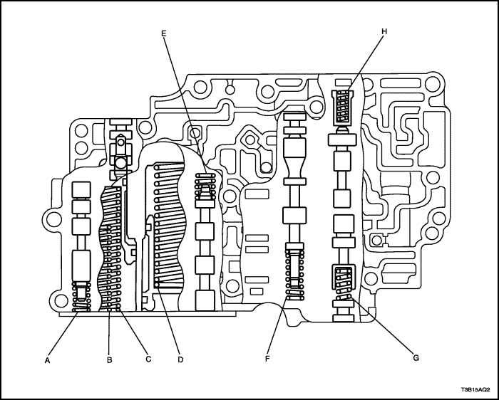
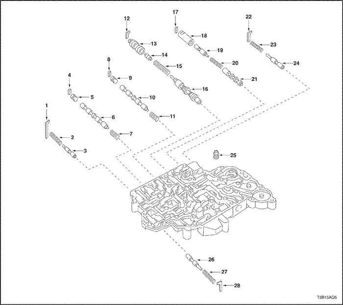
Mark
|
Name (Color)
|
Free length/Outer diameter mm (in.)
|
Total number of coils
|
|
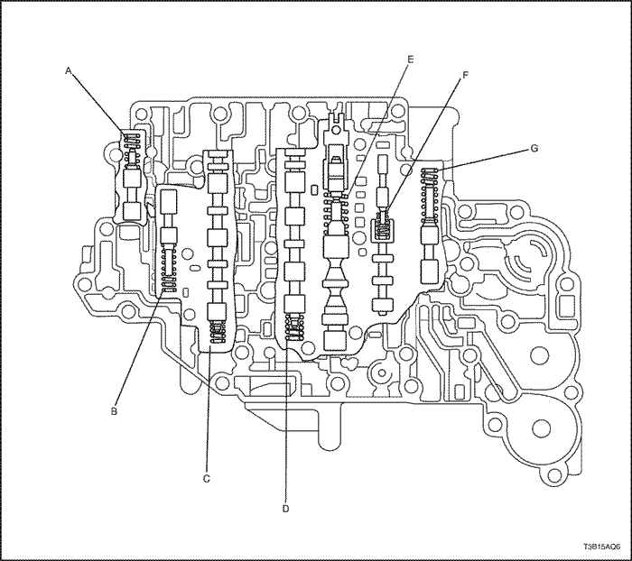
A
|
3-4 shift timing valve (Pink)
|
28.41 (1.1185) / 6.4 (0.252)
|
10.49
|
|
B
|
2nd brake accumulator piston,(None) Inner
|
45.90 (1.8071) / 10.5 (0.413)
|
16.9
|
|
C
|
2nd brake accumulator piston,(White) Outer
|
69.00 (2.7165) / 16.0 (0.630)
|
15.1
|
|
D
|
Reverse clutch accumulator piston (None)
|
65.40(2.5748) / 17.0 (0.669)
|
13.7
|
|
E
|
3-4 shift valve (Red)
|
25.50 (1.0039) / 9.73 (0.3831)
|
7.75
|
|
F
|
Secondary regulator valve (White)
|
34.56 (1.3606) / 8.8 (0.346)
|
12.27
|
|
G
|
Reverse control valve (None)
|
25.58 (1.0071) / 8.64 (0.3402)
|
8.75
|
|
H
|
Lock up control valve (Yellow)
|
20.87 (0.8217) / 5.55 (0.2185)
|
11.15
|
Mark
|
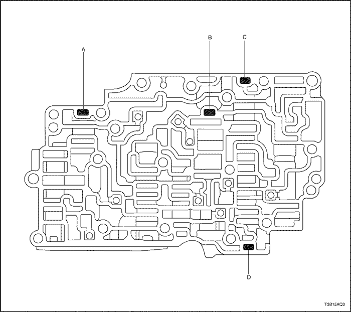
Retainer
|
Height/Width/Thickness mm (in.)
|
|
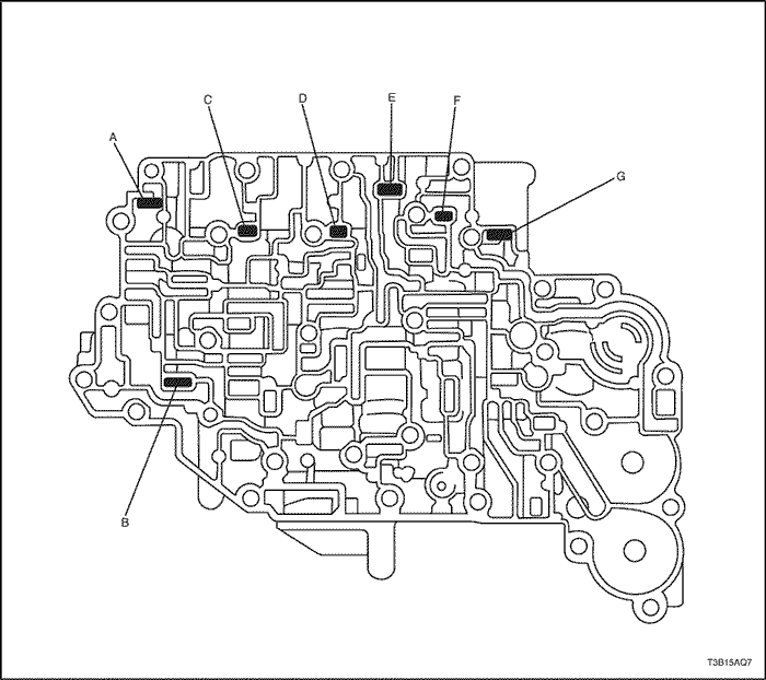
A
|
Check valve
|
11.5 (0.453) / 5.0 (0.197) / 3.2 (0.126)
|
|
B
|
Secondary regulator valve
|
16.0 (0.630) / 5.0 (0.197) / 3.2 (0.126)
|
|
C
|
Lock up control valve
|
16.0 (0.630) / 5.0 (0.197) / 3.2 (0.126)
|
|
D
|
Reverse control valve
|
11.5 (0.453) / 5.0 (0.197) / 3.2 (0.126)
|
|
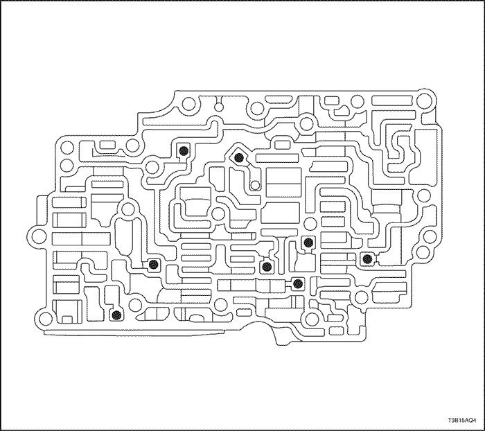
Check ball mm(in).
|
5.535 (0.21791)
|
Mark
|
Name (Color)
|
Free length/Outer diameter mm (in.)
|
Total number of coils
|
|
A
|
4-3 shift timing valve No.1 (None)
|
33.95 (1.3366) / 8.2 (0.323)
|
12.5
|
|
B
|
Low modulator valve (None)
|
30.43 (1.1980) / 7.75 (0.3051)
|
12.72
|
|
C
|
2-3 shift valve (Red)
|
25.50 (1.0039) / 9.73 (8.1694)
|
7.75
|
|
D
|
1-2 shift valve (Red)
|
25.50 (1.0039) / 9.73 (8.1694)
|
7.75
|
|
E
|
Primary regulator valve (None)
|
50.53 (1.9894) / 13.6 (0.535)
|
11.07
|
|
F
|
Lock up relay valve (Red)
|
23.42 (0.9221) / 5.86 (0.2307)
|
12.25
|
|
G
|
Solenoid modulator valve (Yellow)
|
32.13 (1.2650) / 8.0 (0.315)
|
15.75
|
Mark
|
Retainer
|
Height/Width/Thickness mm (in.)
|
|
A
|
4-3 shift timing valve No.1
|
36.0 (1.417) / 5.0 (0.197) / 3.2 (0.126)
|
|
B
|
Low modulator valve
|
24.0 (0.945) / 5.0 (0.197) / 3.2 (0.126)
|
|
C
|
2-3 shift valve
|
10.0 (0.394) / 5.0 (0.197) / 3.2 (0.126)
|
|
D
|
1-2 shift valve
|
10.0 (0.394) / 5.0 (0.197) / 3.2 (0.126)
|
|
E
|
Primary regulator valve
|
9.8 (0.386) / 5.2 (0.205) / 3.2 (0.126)
|
|
F
|
Lock up relay valve
|
16.0 (0.630) / 5.0 (0.197) / 3.2 (0.126)
|
|
G
|
Solenoid modulator valve
|
24.0 (0.945) / 5.0 (0.197) / 3.2 (0.126)
|
Thickness
|
Thickness
|
|
0.95 (0.0374)
|
1.10 (0.0433)
|
|
1.00 (0.0394)
|
1.15 (0.0453)
|
|
1.05 (0.0413)
|
1.20 (0.0472)
|
Mark
|
Thickness
|
Mark
|
Thickness
|
|
A
|
1.80 (0.0709)
|
N
|
2.26 (0.0890)
|
|
B
|
1.85 (0.0728)
|
P
|
2.29 (0.0902)
|
|
C
|
1.90 (0.0748)
|
Q
|
2.32 (0.0913)
|
|
D
|
1.95 (0.0768)
|
R
|
2.35 (0.0925)
|
|
E
|
2.00 (0.0787)
|
S
|
2.40 (0.0945)
|
|
F
|
2.05 (0.0807)
|
T
|
2.45 (0.0965)
|
|
G
|
2.08 (0.0819)
|
U
|
2.50 (0.0984)
|
|
H
|
2.11 (0.0831)
|
V
|
2.55 (0.1004)
|
|
J
|
2.14 (0.0843)
|
W
|
2.60 (0.1024)
|
|
K
|
2.17 (0.0854)
|
X
|
2.65 (0.1043)
|
|
L
|
2.20 (0.0866)
|
Y
|
2.70 (0.01063)
|
|
M
|
2.23 (0.0878)
|
.
|
.
|
| © Copyright Chevrolet Europe. All rights reserved |


