To the top of the document
Aveo
To Previous Page To Next Page
GMDE Start Page Load static TOC Load dynamic TOC Help?

UNIT REPAIR


T3B15B34
Display graphicTranslations of text in graphics


Major Component Disassembly

Tools Required

J-6125-B Slide Hammer
J-22888-20-A BearingPuller with J-22888-35 Puller Legs
KM-553-A Fifth Gear Puller
J-36633 Snap Ring Retainer
KM-113-2 Base
J-42469 Shift Rod Remover
KM-552 Fixture

Disassembly Procedure

  1. Remove the transaxle from the vehicle. Refer to "Transaxle Assembly" in this section.
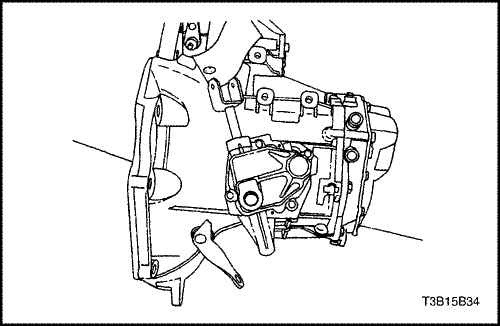
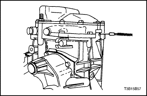
  2. Remove the filler plug at the cover.


  3. S7C35B02
    Display graphicTranslations of text in graphics


  4. Remove the bolts from the gearshift lever cover.


  5. T3B15B36
    Display graphicTranslations of text in graphics


  6. Remove the gearshift lever cover.
  7. Remove the gearshift cover gasket.


  8. S7B35B02
    Display graphicTranslations of text in graphics


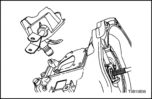
  9. Remove the reverse lever clip.
  10. Remove the reverse assist lever.


  11. S7C35B03
    Display graphicTranslations of text in graphics


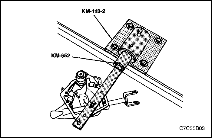
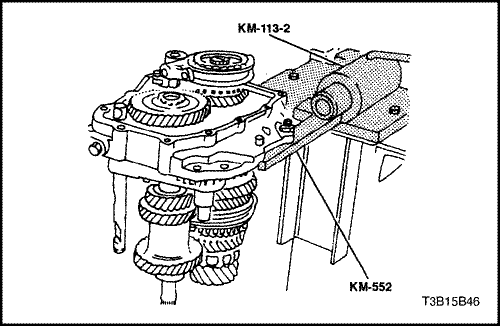
  12. Bolt the gearshift lever cover to the fixture KM-552.
  13. Position the fixture KM-552 into the base KM-113-2.


  14. S7B35B04
    Display graphicTranslations of text in graphics


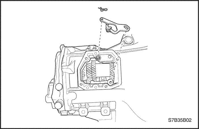
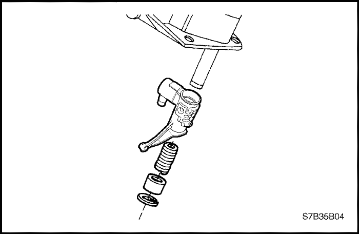
  15. Remove the snap ring, the bushing, the spring, and the intermediate lever.


  16. S7C35B04
    Display graphicTranslations of text in graphics


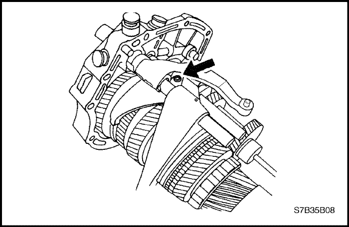
  17. Remove the shift finger lever pin.


  18. S7C35B05
    Display graphicTranslations of text in graphics


  19. Remove the gearshift rod and the shift finger lever.


  20. T3B15B41
    Display graphicTranslations of text in graphics


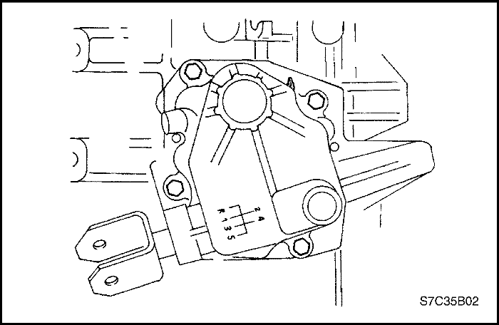
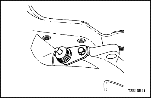
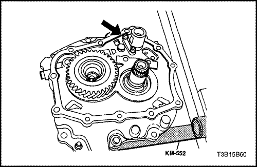
  21. Remove the bolt and the speedometer-driven gear from the transaxle housing.


  22. T3B15B42
    Display graphicTranslations of text in graphics


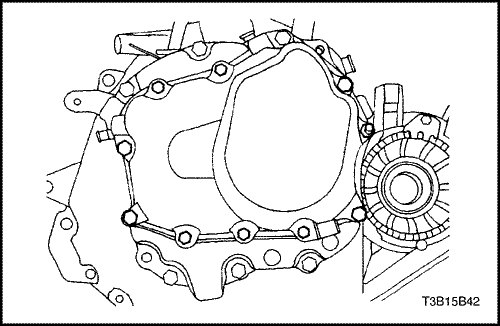
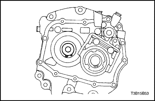
  23. Remove the transaxle cover bolts.


  24. T3B15B43
    Display graphicTranslations of text in graphics


  25. Remove the transaxle cover.


  26. T3B15B44
    Display graphicTranslations of text in graphics


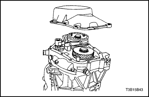
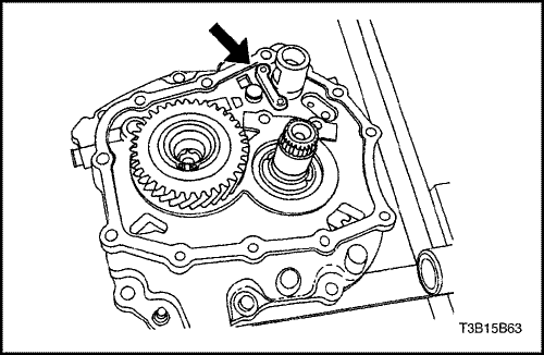
  27. Shift the transaxle into second gear.
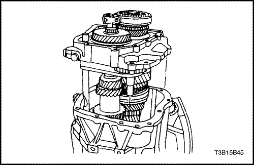
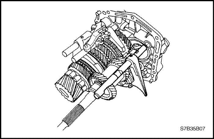
  28. Remove the bearing plate bolts.


  29. T3B15B45
    Display graphicTranslations of text in graphics


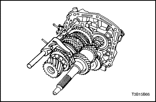
  30. Remove the bearing plate from the case with the shafts attached.


  31. T3B15B46
    Display graphicTranslations of text in graphics


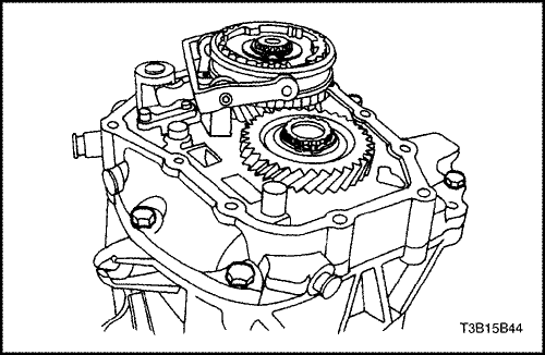
  32. Shift the transaxle into reverse (R).
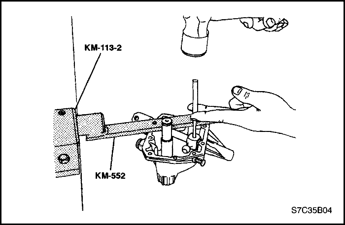
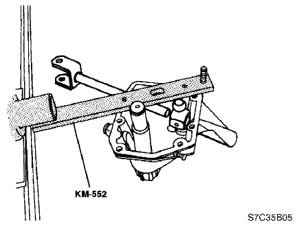
  33. Bolt the bearing plate to the fixture KM-552 and install the fixture KM-552 into the base KM-113-2.


  34. T3B15B47
    Display graphicTranslations of text in graphics


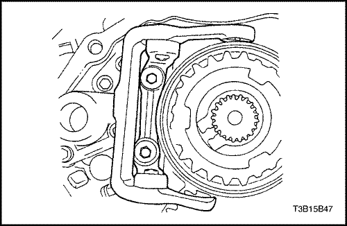
  35. Remove the bolts and the fifth-gear fork from the bearing plate.


  36. T3B15B48
    Display graphicTranslations of text in graphics


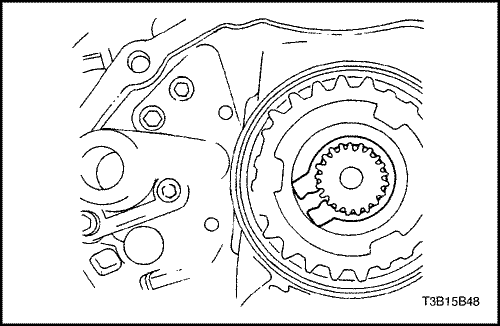
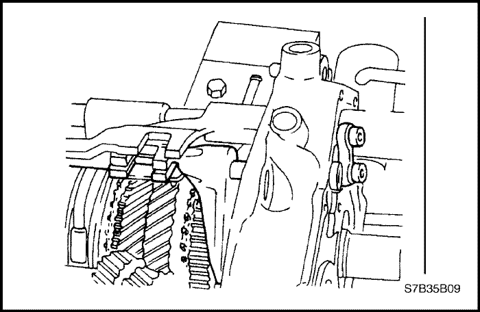
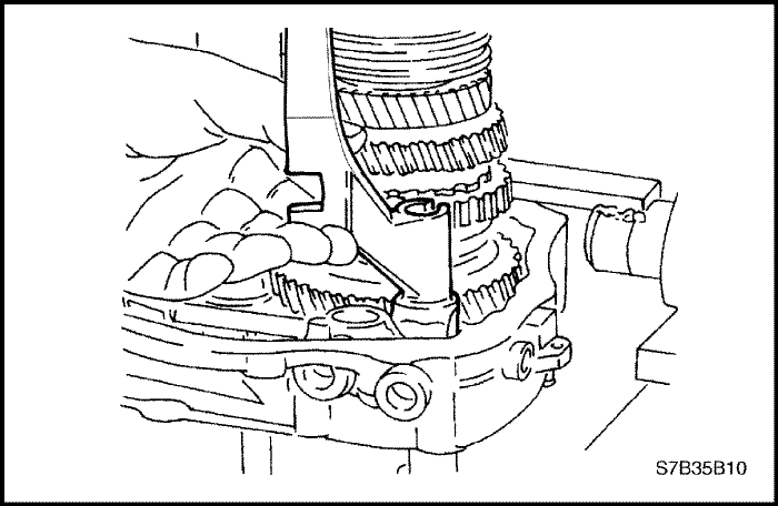
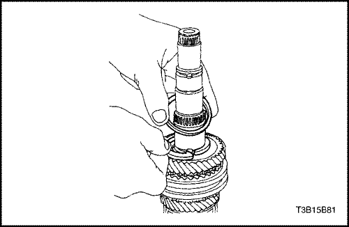
  37. Remove the mainshaft-driven fifth-speed assembly snap ring.


  38. T3B15B49
    Display graphicTranslations of text in graphics


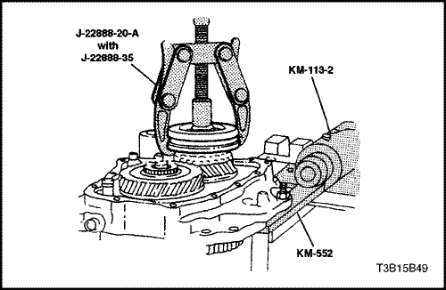
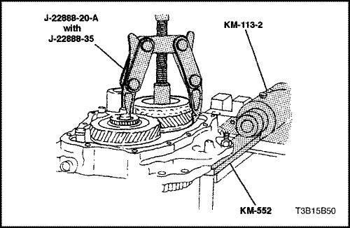
  39. Remove the fifth driven gear synchronizer sleeve and the synchronizer gear using the bearing puller J-22888-20-A with the puller legs J-22888-35.


  40. T3B15B50
    Display graphicTranslations of text in graphics


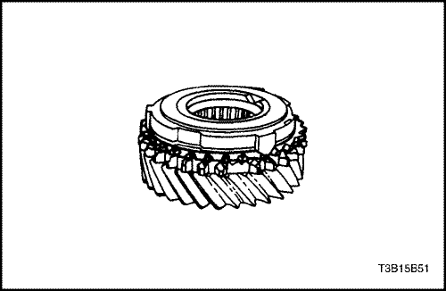
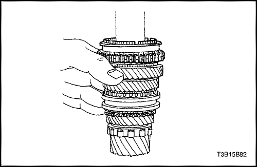
  41. Remove the mainshaft-driven fifth-gear assembly.


  42. T3B15B51
    Display graphicTranslations of text in graphics


  43. Remove the brass synchronizer ring.


  44. T3B15B52
    Display graphicTranslations of text in graphics


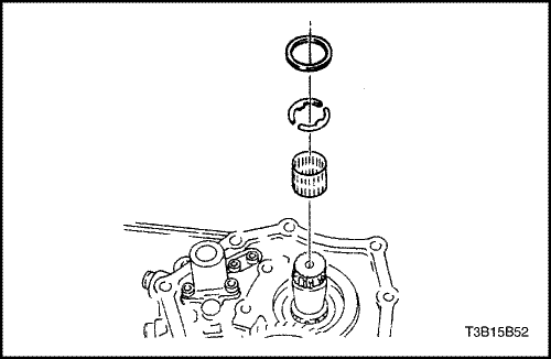
  45. Remove the needle bearing, the retaining ring, and the thrust washers.


  46. T3B15B53
    Display graphicTranslations of text in graphics


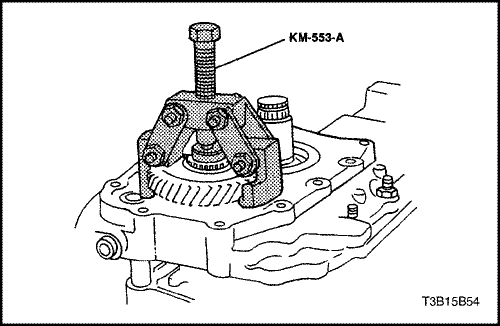
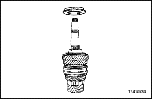
  47. Remove the input drive fifth-gear snap ring.


  48. T3B15B54
    Display graphicTranslations of text in graphics


  49. Remove the input drive fifth gear using the fifth-gear puller KM-553-A.


  50. S7B35B05
    Display graphicTranslations of text in graphics


  51. Remove the bolts and the fifth-gearshift connector from the bearing plate using the pawl.


  52. T3B15B56
    Display graphicTranslations of text in graphics


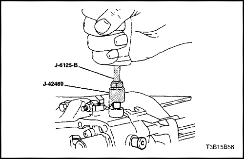
  53. Remove the four shift-rod plugs using the shift rod remover J-42469 and the slide hammer J-6125-B.


  54. T3B15B57
    Display graphicTranslations of text in graphics


  55. Remove the spring and the rod lock pin from the small plug hole.


  56. S7B35B06
    Display graphicTranslations of text in graphics


  57. Remove the pin from the reverse gearshift rod/fork assembly.


  58. S7B35B07
    Display graphicTranslations of text in graphics


  59. Remove the reverse gearshift rod/fork assembly from the bearing plate.


  60. T3B15B60
    Display graphicTranslations of text in graphics


  61. Remove the bolts from the support bracket.


  62. S7B35B08
    Display graphicTranslations of text in graphics


  63. Remove the first-second gearshift fork holding pin.


  64. S7B35B09
    Display graphicTranslations of text in graphics


  65. Drive the first-second gearshift rod out until it is just free of the bearing plate.


  66. T3B15B63
    Display graphicTranslations of text in graphics


  67. Remove the support bracket from the bearing plate.


  68. T3B15B64
    Display graphicTranslations of text in graphics


  69. Remove the third-fourth gearshift fork holding pin and the third-fourth gearshift rod.


  70. S7B35B10
    Display graphicTranslations of text in graphics


  71. Remove the fifth gearshift lever from the bearing plate.


  72. T3B15B66
    Display graphicTranslations of text in graphics


  73. Remove the first-second gearshift rod.


  74. T3B15B67
    Display graphicTranslations of text in graphics


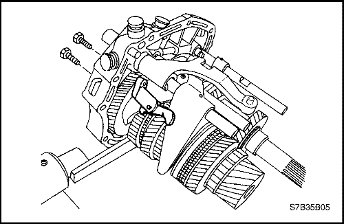
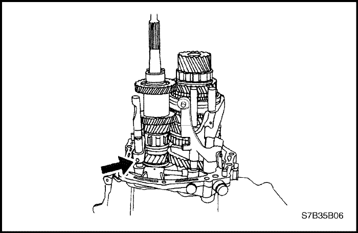
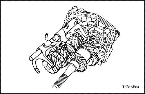
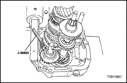
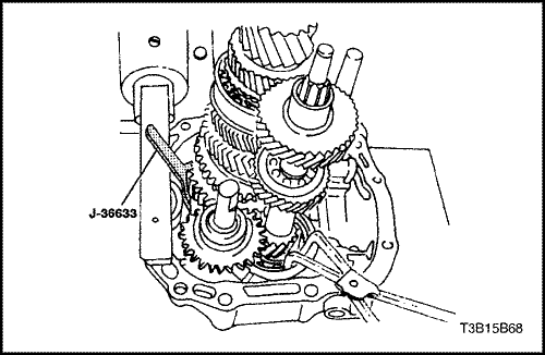
  75. Compress the snap ring holding the mainshaft and secure it with the snap ring retainer J-36633.


  76. T3B15B68
    Display graphicTranslations of text in graphics


  77. Hold the snap ring open at the base of the input shaft using the snap ring pliers.
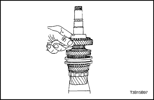
  78. Remove the mainshaft assembly and the input shaft assembly from the bearing plate.


T3B15B69
Display graphicTranslations of text in graphics


Input Shaft and Cluster Gear

Tools Required

J-22912-01 Universal Bearing Puller

Disassembly Procedure

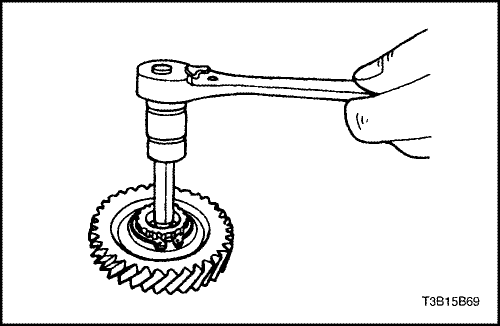
  1. Remove the detent screw at the end of the input driveshaft.


  2. T3B15B70
    Display graphicTranslations of text in graphics


  3. Remove the snap ring at the base of the gear cluster.


  4. T3B15B71
    Display graphicTranslations of text in graphics


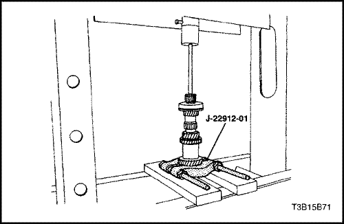
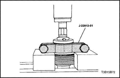
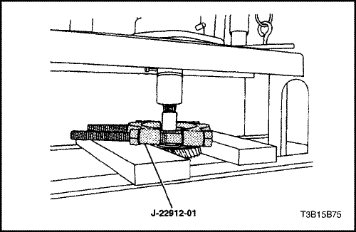
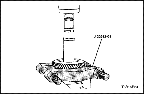
  5. Press the input driveshaft from the input shaft cluster gear using the universal bearing puller J-22912-01.


  6. T3B15B72
    Display graphicTranslations of text in graphics


  7. Remove the cluster shaft bearing from the input shaft gear cluster using universal bearing puller J-22912-01.


T3B15B73
Display graphicTranslations of text in graphics


Assembly Procedure

  1. Press the cluster shaft bearing onto the input shaft gear cluster.


  2. T3B15B74
    Display graphicTranslations of text in graphics


  3. Press the input driveshaft into the input shaft gear cluster assembly.


  4. T3B15B70
    Display graphicTranslations of text in graphics


  5. Install the snap ring at the base of the gear cluster.


  6. T3B15B69
    Display graphicTranslations of text in graphics


  7. Install the detent screw at the end of the input driveshaft.
  8. Tighten
    Tighten the input driveshaft detent screw to 15 N•m (11 lb-ft).
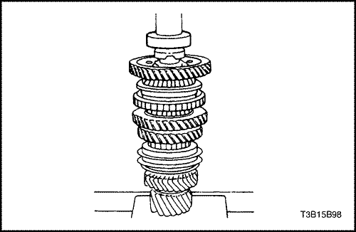


T3B15B75
Display graphicTranslations of text in graphics


Mainshaft

Tools Required

J-22912-01 Universal Bearing Puller

Disassembly Procedure

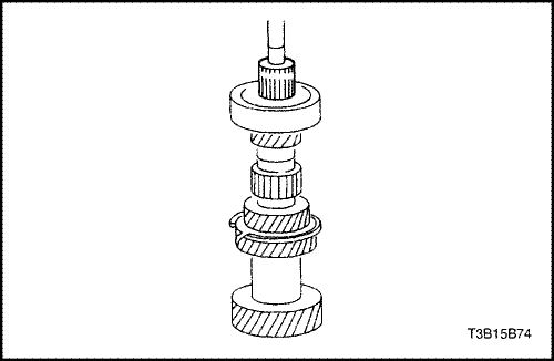
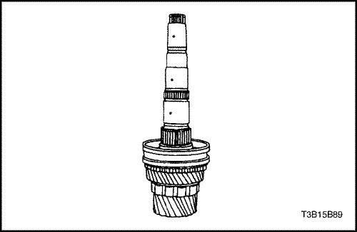
  1. Remove the mainshaft bearing using the universal bearing puller J-22912-01.


  2. T3B15B76
    Display graphicTranslations of text in graphics


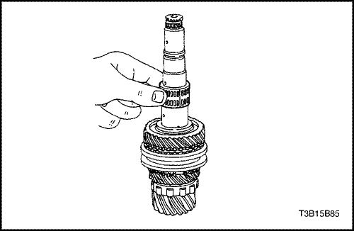
  3. Remove the snap ring.


  4. T3B15B77
    Display graphicTranslations of text in graphics


  5. Remove the first gear, the flat-type first-gear needle bearing, and the mainshaft wear plate.


  6. T3B15B78
    Display graphicTranslations of text in graphics


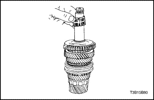
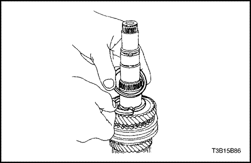
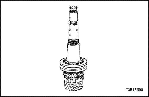
  7. Remove the synchronizer hub sleeve that contains the synchronizer spring.
  8. Remove the outer blocking ring.


  9. T3B15B79
    Display graphicTranslations of text in graphics


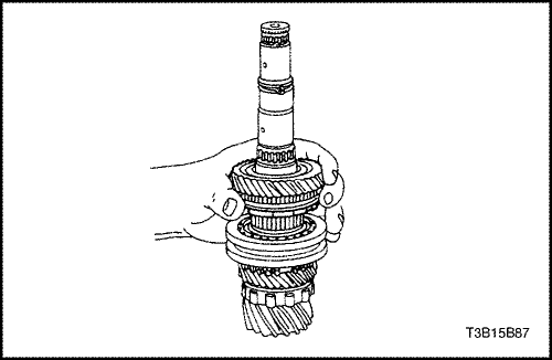
  10. Remove the keys from the first-second synchronizer gear.


  11. T3B15B80
    Display graphicTranslations of text in graphics


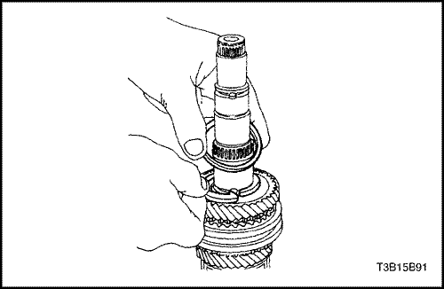
  12. Remove the barrel-type first-gear needle bearing.


  13. T3B15B81
    Display graphicTranslations of text in graphics


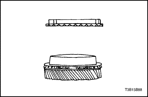
  14. Remove the snap ring and the washer.


  15. T3B15B82
    Display graphicTranslations of text in graphics


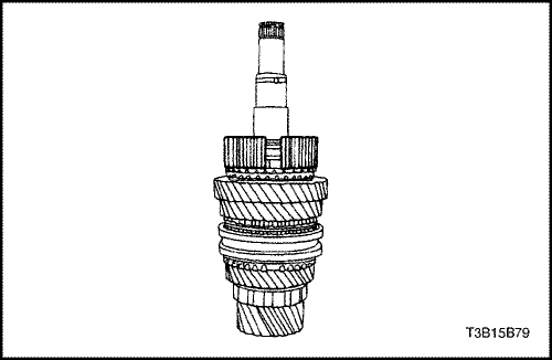
  16. Remove the first-second synchronizer gear from the mainshaft.


  17. T3B15B83
    Display graphicTranslations of text in graphics


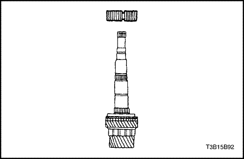
  18. Remove the first-second gear blocking ring.


  19. T3B15B84
    Display graphicTranslations of text in graphics


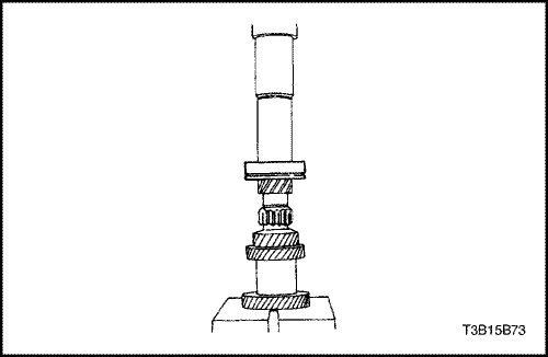
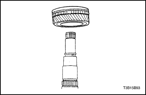
  20. Remove the second gear using the universal bearing puller J-22912-01.


  21. T3B15B85
    Display graphicTranslations of text in graphics


  22. Remove the second-gear needle bearing.


  23. T3B15B86
    Display graphicTranslations of text in graphics


  24. Remove the ring and the thrust washer.


  25. T3B15B87
    Display graphicTranslations of text in graphics


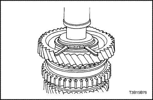
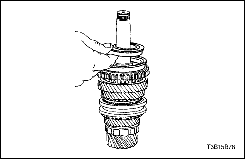
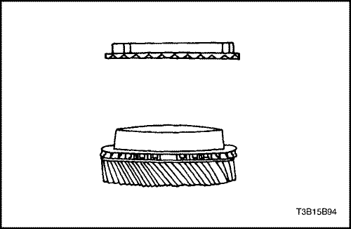
  26. Remove the third gear and the synchronizer blocking ring.


  27. T3B15B88
    Display graphicTranslations of text in graphics


  28. Separate the synchronizer blocking ring from the third gear.


  29. T3B15B89
    Display graphicTranslations of text in graphics


  30. Remove the third-gear needle bearing from the mainshaft.


  31. T3B15B90
    Display graphicTranslations of text in graphics


  32. Remove the synchronizer sleeve containing the keys and the spring.


  33. T3B15B91
    Display graphicTranslations of text in graphics


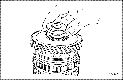
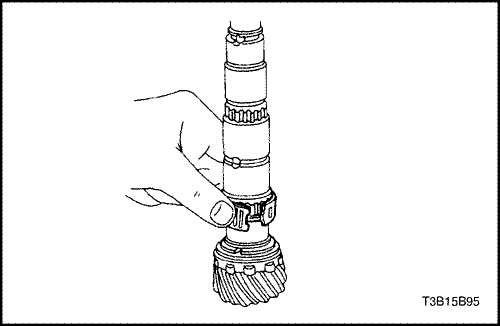
  34. Remove the snap ring and the washer from the mainshaft.


  35. T3B15B92
    Display graphicTranslations of text in graphics


  36. Remove the third-fourth synchronizer gear containing the synchronizer spring.


  37. T3B15B93
    Display graphicTranslations of text in graphics


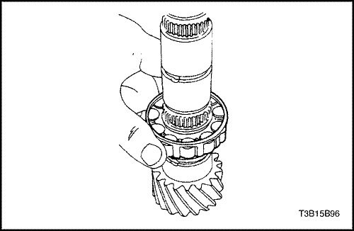
  38. Remove the fourth-gear assembly.


  39. T3B15B94
    Display graphicTranslations of text in graphics


  40. Separate the synchronizer blocking ring from the fourth gear.


  41. T3B15B95
    Display graphicTranslations of text in graphics


  42. Remove the fourth-gear needle bearing, the ring, and the thrust washer.


  43. T3B15B96
    Display graphicTranslations of text in graphics


  44. Remove the mainshaft bearing.


T3B15B96
Display graphicTranslations of text in graphics


Assembly Procedure

  1. Install the mainshaft bearing.


  2. T3B15B95
    Display graphicTranslations of text in graphics


  3. Install the ring, the thrust washer, and the fourth-gear needle bearing.


  4. T3B15B94
    Display graphicTranslations of text in graphics


  5. Attach the synchronizer blocking ring to the fourth gear.


  6. T3B15B93
    Display graphicTranslations of text in graphics


  7. Install the fourth-gear assembly.


  8. T3B15B92
    Display graphicTranslations of text in graphics


  9. Install the third-fourth gear synchronizer containing the synchronizer spring.


  10. T3B15B91
    Display graphicTranslations of text in graphics


  11. Install the snap ring and the washer around the mainshaft.


  12. T3B15B90
    Display graphicTranslations of text in graphics


  13. Install the synchronizer sleeve containing the keys and the spring.


  14. T3B15B89
    Display graphicTranslations of text in graphics


  15. Install the third-gear needle bearing.


  16. T3B15B88
    Display graphicTranslations of text in graphics


  17. Attach the synchronizer blocking ring to the third gear.


  18. T3B15B87
    Display graphicTranslations of text in graphics


  19. Install the third-gear assembly.


  20. T3B15B86
    Display graphicTranslations of text in graphics


  21. Install the thrust washer and the ring.


  22. T3B15B85
    Display graphicTranslations of text in graphics


  23. Install the second-gear needle bearing.


  24. T3B15B97
    Display graphicTranslations of text in graphics


  25. Install the second gear.


  26. T3B15B83
    Display graphicTranslations of text in graphics


  27. Install the first-second gear blocking ring.


  28. T3B15B82
    Display graphicTranslations of text in graphics


  29. Install the first-second synchronizer gear.


  30. T3B15B81
    Display graphicTranslations of text in graphics


  31. Install the washer and the snap ring.


  32. T3B15B80
    Display graphicTranslations of text in graphics


  33. Install the first-gear needle bearing.


  34. T3B15B79
    Display graphicTranslations of text in graphics


  35. Install the keys onto the first-second synchronizer gear.


  36. T3B15B78
    Display graphicTranslations of text in graphics


  37. Install the synchronizer hub sleeve containing the synchronizer spring.


  38. T3B15B77
    Display graphicTranslations of text in graphics


  39. Install the outer blocking ring.
  40. Install the mainshaft wear plate, the flat-type firstgear needle bearing, and the first gear.


  41. T3B15B76
    Display graphicTranslations of text in graphics


  42. Install the snap ring.


  43. T3B15B98
    Display graphicTranslations of text in graphics


  44. Press on the mainshaft bearing.


To Previous Page To Next Page
© Copyright Chevrolet Europe. All rights reserved