To the top of the document
Aveo
To Previous Page To Next Page
GMDE Start Page Load static TOC Load dynamic TOC Help?


T3B15B36
Display graphicTranslations of text in graphics


Housing Case

Disassembly Procedure

  1. Remove the transaxle from the vehicle. Refer to "Transaxle Assembly" in this section.
  2. Remove the shift lever cover bolts and the shift lever cover. Do not disassemble the shift lever cover.
  3. Remove the gearshift cover gasket.


  4. S7B35B02
    Display graphicTranslations of text in graphics


  5. Remove the reverse lever clip.
  6. Remove the reverse assist lever.


  7. T3B15B43
    Display graphicTranslations of text in graphics


  8. Remove the transaxle cover bolts and the transaxle cover.


  9. T3B15B45
    Display graphicTranslations of text in graphics


  10. Remove the bearing plate bolts and the bearing plate, with the shafts attached. Do not disassemble the shafts.


  11. T3B15B99
    Display graphicTranslations of text in graphics


  12. Remove the differential from the transaxle housing. Do not disassemble the differential. Refer to "Differential" in this section.
  13. Remove the backup lamp switch from the transaxle housing.


  14. T3B15B41
    Display graphicTranslations of text in graphics


  15. Remove the clutch-release bearing and the clutch-release bearing guide. Refer to Section 5C, Clutch.
  16. Remove the speedometer-driven gear bolt and the speedometer-driven gear from the transaxle housing.


T3B15B41
Display graphicTranslations of text in graphics


Assembly Procedure

  1. Install the speedometer-driven gear bolt and the speedometer-driven gear into the transaxle housing.
  2. Tighten
    Tighten the speedometer-driven gear bolt to 5 N•m (44 lb-in)


    T3B15B99
    Display graphicTranslations of text in graphics


  3. Install the clutch-release bearing guide and the clutch-release bearing. Refer to Section 5C, Clutch.
  4. Install the backup lamp switch into the transaxle housing.
  5. Tighten
    Tighten the backup lamp switch to 20 N•m (15 lb-ft).


    T3B15B45
    Display graphicTranslations of text in graphics


  6. Install the differential into the transaxle housing. Refer to "Differential" in this section.
  7. Install the bearing plate, with the shafts attached.
  8. Install the bearing plate bolts.
  9. Tighten
    Tighten the bearing plate bolts to 22 N•m (16 lb-ft).


    T3B15B43
    Display graphicTranslations of text in graphics


  10. Install the transaxle cover and the transaxle cover bolts.
  11. Tighten
    Tighten the transaxle cover bolts to 18 N•m (13 lb-ft).


    S7B35B02
    Display graphicTranslations of text in graphics


  12. Install the reverse assist lever.
  13. Install the reverse lever clip.


  14. T3B15B36
    Display graphicTranslations of text in graphics


  15. Install the gearshift cover gasket.
  16. Install the gearshift lever cover and the gearshift lever cover bolts.
  17. Tighten
    Tighten the gearshift lever cover bolts to 22 N•m (16 lb-ft).

  18. Install the transaxle into the vehicle. Refer to "Transaxle Assembly" in this section.


T3B15BA1
Display graphicTranslations of text in graphics


Differential

Tools Required

KM-520 Remover/Installer
KM-525 Installer
J-22888-20-A Bearing Puller with J-22888-35 Puller Legs
KM-522 Installer

Disassembly Procedure

  1. Remove the differential cover bolts, the differential cover, and the differential cover gasket.


  2. T3B15BA2
    Display graphicTranslations of text in graphics


  3. Remove the bearing-adjusting ring retainer plate bolt and the bearing-adjusting ring retainer plate.


  4. T3B15BA3
    Display graphicTranslations of text in graphics


  5. Remove the bearing-adjusting ring using the remover/ installer KM-520.


  6. T3B15BA4
    Display graphicTranslations of text in graphics


  7. Remove the right-side bearing-retainer bolts and the right-side bearing retainer.


  8. T3B15BA5
    Display graphicTranslations of text in graphics


  9. Remove the differential assembly from the transaxle case.


  10. T3B15BA6
    Display graphicTranslations of text in graphics


  11. Remove the ring gear bolts.


  12. T3B15BA7
    Display graphicTranslations of text in graphics


  13. Separate the ring gear from the differential housing.


  14. T3B15BA8
    Display graphicTranslations of text in graphics


  15. Drive the pinion gear shaft lock pin from the differential housing and the pinion gear shaft.


  16. T3B15BA9
    Display graphicTranslations of text in graphics


  17. Remove the pinion gear shaft.


  18. T3B15BB1
    Display graphicTranslations of text in graphics


  19. Remove the pinion gears and the washers.
  20. Remove the side gears and the side thrust washers.


  21. T3B15BB2
    Display graphicTranslations of text in graphics


  22. Remove both of the differential bearings using the bearing puller J-22888-20-A with the puller legs J-22888-35.


  23. T3B15BB3
    Display graphicTranslations of text in graphics


  24. Remove the speedometer drive gear from the differential gear housing.


T3B15BB4
Display graphicTranslations of text in graphics


Assembly Procedure

  1. Install the speedometer drive gear onto the differential gear housing using the installer KM-525.


  2. T3B15BB5
    Display graphicTranslations of text in graphics


  3. Install both of the differential bearings using the installer KM-522.


  4. T3B15BB1
    Display graphicTranslations of text in graphics


  5. Install the side gears and the side thrust washers into the differential housing.
  6. Install the differential pinion gears and the differential pinion gear washers into the differential housing.


  7. T3B15BA9
    Display graphicTranslations of text in graphics


  8. Install the pinion gear shaft into the differential housing.


  9. T3B15BB6
    Display graphicTranslations of text in graphics


  10. Install the pinion gear shaft lock pin into the differential housing and the pinion gear shaft.


  11. T3B15BA6
    Display graphicTranslations of text in graphics


  12. Install the ring gear and the ring-gear bolts.
  13. Tighten
    Tighten the ring-gear bolts to 70 N•m (52 lb-ft).


    T3B15BA5
    Display graphicTranslations of text in graphics


  14. Install the differential assembly into the transaxle case.


  15. T3B15BA4
    Display graphicTranslations of text in graphics


  16. Install the right-side bearing retainer and the rightside bearing retainer bolts.
  17. Tighten
    Tighten the right-side bearing retainer bolts to 25 N•m (18 lb-ft).


    T3B15BA3
    Display graphicTranslations of text in graphics


  18. Install the bearing-adjusting ring.
  19. Tighten the bearing-adjusting ring using the remover/ installer KM-520.
  20. Tighten
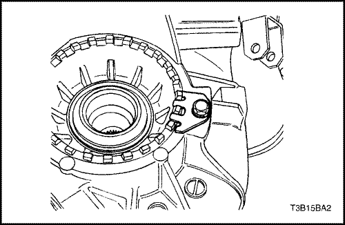
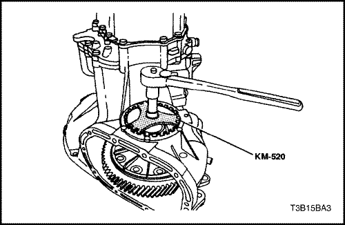
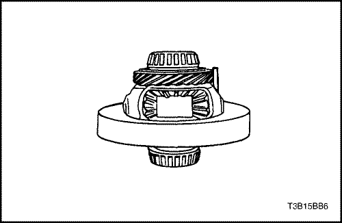
    Tighten the bearing adjusting ring until there is no end play with the differential.
    Adjust the preload on the differential bearings.
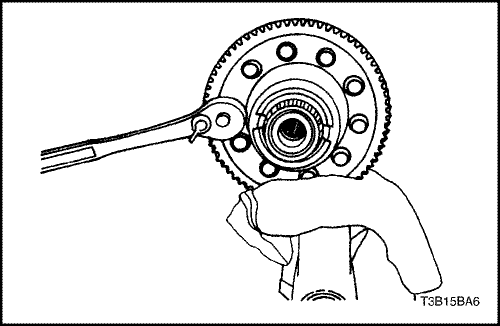
    Used Bearings:
    1 N•m (9 lb-in) required to rotate the differential one revolution per second.
    New Bearings:
    2 N•m (18 lb-in) required to rotate the differential one revolution per second.
    Tighten or loosen the bearing ring adjuster to get the required preload on the bearings.


    T3B15BA2
    Display graphicTranslations of text in graphics


  21. Install the bearing-adjusting ring-retainer plate and the bearing-adjusting ring-retainer plate bolt.
  22. Tighten
    Tighten the bearing-adjusting ring-retainer plate bolt to 5 N•m (44 lb-in).


    T3B15BA1
    Display graphicTranslations of text in graphics


  23. Install the differential cover gasket, the differential cover, and the differential cover bolts.
  24. Tighten
    Tighten the differential cover bolts to 40 N•m (30 lb-ft).


T3B15B68
Display graphicTranslations of text in graphics


Major Component Assembly

Tools Required

J-36633 Snap Ring Retainer
KM-334 Installer Sleeve
KM-552 Fixture
KM-554 Installer
KM-113-2 Base

Assembly Procedure

  1. Join the mainshaft and the input shaft.
  2. Compress the snap ring at the base of the mainshaft and hold with the snap ring retainer J-36633.
  3. Hold the snap ring at the base of the input driveshaft with the snap ring pliers.
  4. Install the mainshaft/input shaft assembly onto the bearing plate.
  5. Release the mainshaft snap ring and the input shaft snap ring.


  6. S7B35B10
    Display graphicTranslations of text in graphics


  7. Position the first-second gearshift fork.
  8. Install the fifth gearshift lever into the bearing plate.


  9. T3B15B64
    Display graphicTranslations of text in graphics


  10. Install the third-fourth gearshift rod/fork holding pin.


  11. T3B15B63
    Display graphicTranslations of text in graphics


  12. Install the support bracket onto the bearing plate.


  13. S7B35B11
    Display graphicTranslations of text in graphics


  14. Install the first-second gearshift rod/fork onto the bearing plate.


  15. S7B35B08
    Display graphicTranslations of text in graphics


  16. Install the first-second gearshift fork holding pin.


  17. T3B15B60
    Display graphicTranslations of text in graphics


  18. Install the support bracket bolts.
  19. Tighten
    Tighten the support bracket bolts to 7 N•m (62 lb-in).


    S7B35B07
    Display graphicTranslations of text in graphics


  20. Install the reverse gearshift rod/fork onto the bearing plate.


  21. S7B35B06
    Display graphicTranslations of text in graphics


  22. Install the reverse gearshift rod/fork holding pin.


  23. T3B15B57
    Display graphicTranslations of text in graphics


  24. Install the rod lock pin and spring into the small plug hole.


  25. T3B15BB8
    Display graphicTranslations of text in graphics


  26. Install the fourth-gearshift rod plugs.


  27. S7B35B05
    Display graphicTranslations of text in graphics


  28. Install the bolts and the fifth-gearshift connector onto the bearing plate, using the pawl.
  29. Tighten
    Tighten the fifth-gearshift connector bolts to 7 N•m (62 lb-in).


    S7B35B12
    Display graphicTranslations of text in graphics


  30. Install the input drive fifth gear using the installer KM-554 and the installer sleeve KM-334.


  31. T3B15B53
    Display graphicTranslations of text in graphics


  32. Install the snap rings securing the fifth-drive gear.


  33. T3B15B52
    Display graphicTranslations of text in graphics


  34. Install the thrust washers, the retaining ring, and the needle bearing into the mainshaft-driven fifth-gear assembly.


  35. T3B15B51
    Display graphicTranslations of text in graphics


  36. Install the brass synchronizer ring onto the mainshaft- driven fifth-gear assembly.


  37. S7B35B13
    Display graphicTranslations of text in graphics


  38. Install the mainshaft-driven fifth-gear assembly.
  39. Install the fifth-drive gear synchronizer gear and the synchronizer sleeve using installer KM-554.


  40. T3B15B48
    Display graphicTranslations of text in graphics


  41. Install the snap ring holding the fifth speed-driven assembly.


  42. T3B15B47
    Display graphicTranslations of text in graphics


  43. Install the bolts and the fifth-gear fork onto the bearing plate.
  44. Tighten
    Tighten the fifth-gear fork bolts to 22 N•m (16 lb-ft).


    T3B15B45
    Display graphicTranslations of text in graphics


  45. Remove the bearing plate from the fixture KM-552.
  46. Shift the transaxle into second gear.
  47. Install the bearing plate, with the shafts attached, into the case.


  48. T3B15B44
    Display graphicTranslations of text in graphics


  49. Install the bearing plate bolts.
  50. Tighten
    Tighten the bearing plate bolts to 22 N•m (16 lb-ft).


    T3B15B41
    Display graphicTranslations of text in graphics


  51. Install the speedometer-driven gear and the speedometer-housing retaining bolt into the transaxle housing.
  52. Tighten
    Tighten the speedometer housing retaining bolt to 4 N•m (35 lb-in).


    S7C35B05
    Display graphicTranslations of text in graphics


  53. Bolt the gearshift lever cover to the fixture KM-552.
  54. Position the fixture into the base KM-113-2.
  55. Install the gearshift rod, the shift finger lever, and the gearshift lever pin.


  56. S7B35B04
    Display graphicTranslations of text in graphics


  57. Install the snap ring, the bushing, the spring, and the intermediate lever.
  58. Remove the gearshift lever cover from the base KM-113-2 and the fixture KM-552.
  59. Shift the transaxle into NEUTRAL.


  60. S7B35B02
    Display graphicTranslations of text in graphics


  61. Install the reverse assist lever.
  62. Install the reverse lever clip.


  63. T3B15B36
    Display graphicTranslations of text in graphics


  64. Install the gearshift cover gasket.
  65. Install the gearshift lever cover and the gearshift lever cover bolts.
  66. Tighten
    Tighten the gearshift lever cover bolts to 22 N•m (16 lb-ft).


    T3B15B42
    Display graphicTranslations of text in graphics


  67. Install the transaxle cover and the transaxle cover bolts.
  68. Tighten
    Tighten the transaxle cover bolts to 18 N•m (13 lb-ft).

  69. Install the transaxle into the vehicle. Refer to "Transaxle Assembly" in this section.


To Previous Page To Next Page
© Copyright Chevrolet Europe. All rights reserved