Aveo |
||||||||
|
||||||||
Application
|
N•m
|
Lb-Ft
|
Lb-In
|
|
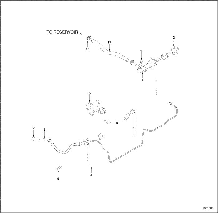
Clutch Master Cylinder Nuts
|
22
|
16
|
-
|
|
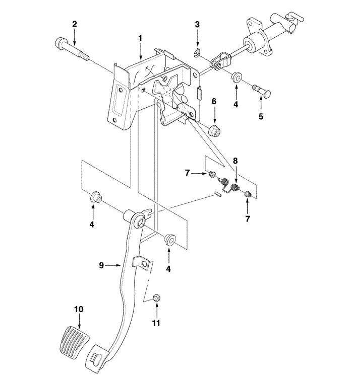
Clutch Pedal Shaft Nut
|
18
|
13
|
-
|
|
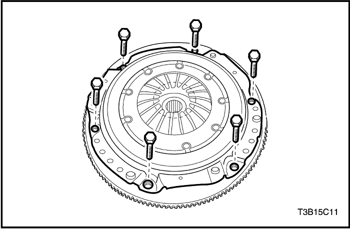
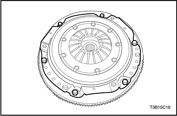
Pressure Plate-to-Flywheel Bolts
|
15
|
11
|
-
|
|
Release Cylinder Bolts
|
20
|
15
|
-
|
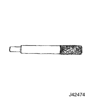 |
J-42474
Clutch Arbor
|
Checks
|
Action
|
|
DEFINITION: When the pedal is pressed to the floor, the shift lever does not move freely in and out of reverse gear.
|
|
|
Check for a loose linkage.
|
Repair or replace loose linkage, if necessary.
|
|
Check for a damaged clutch disc.
|
Replace the damaged clutch disc.
|
|
Check for an improperly installed fork shaft.
|
Remove and properly reinstalled the fork shaft. Very lightly lubricate the fork fingers at the release bearing with wheel bearing grease.
|
|
Check for the clutch disc hub binding on the input shaft splines.
|
Repair or replace the clutch disc hub.
|
|
Check for a warped or bent clutch disc.
|
Replace the warped or bent clutch disc.
|
Checks
|
Action
|
|
Check for the driver improperly operating the vehicle.
|
Correct the driver's operation of the vehicle as necessary.
|
|
Check for an oil-soaked clutch disc.
|
Correct the leak at its source and install a new clutch disc.
|
|
Check for a worn facing or facing torn from the disc.
|
Replace the worn disc with a new disc.
|
|
Check for a warped pressure plate or a warped flywheel.
|
Replace the warped pressure plate or the warped flywheel.
|
|
Check for a weak diaphragm spring.
|
Replace the pressure plate.
|
|
Check for a driven plate that is not seated.
|
Start the engine 30 to 40 times. Do not overheat the engine.
|
|
Check for a driven plate that is overheated.
|
Allow the driven plate to cool.
|
Checks
|
Action
|
|
Check for a burned or a glazed facing caused by oil on the facing.
|
Correct the leak at its source and install a new clutch disc.
|
|
Check for worn splines on the input shaft.
|
Replace the worn input shaft.
|
|
Check for a warped pressure plate or a warped flywheel.
|
Replace the warped pressure plate or the warped flywheel.
|
|
Check for a burned or smeared resin on the flywheel or the pressure plate.
|
Sand off the burned or smeared resin if it is superficial.
Replace any burned or heat-checked parts.
|
Checks
|
Action
|
|
Check for weak retracting springs.
|
Replace the pressure plate.
|
|
Check for a loose release fork.
|
Remove and reinstall the release fork properly.
|
|
Check for oil in the driven plate bumper.
|
Correct the cause of the oil leak and replace the driven disc.
|
|
Check for a damaged driven plate damper spring.
|
Replace the driven disc.
|
Checks
|
Action
|
|
Check for the driver improperly operating the vehicle.
|
Correct the driver's operation of the vehicle as necessary.
|
|
Check for a binding release bearing.
|
Clean and re-lubricate the release bearing. Inspect the release bearing for burrs and nicks.
|
|
Check for an improperly installed release lever.
|
Remove and reinstall the release lever properly.
|
|
Check for a weak linkage return spring.
|
Replace the weak linkage return spring.
|
Checks
|
Action
|
|
Check for a worn release bearing.
|
Replace the worn release bearing.
|
|
Check for a improperly installed release lever.
|
Remove and properly reinstall the fork shaft. Very lightly lubricate the fork fingers at the release bearing with wheel bearing grease.
|
Checks
|
Action
|
|
Check for binding in the linkage or the release bearing.
|
Lubricate and free-up the binding linkage or the release bearing.
|
|
Check for weak pressure plate springs.
|
Replace the pressure plate.
|
Checks
|
Action
|
|
Check for binding in the linkage.
|
Lubricate and free-up the binding linkage.
|
|
Check for a worn driven plate.
|
Replace the worn driven plate.
|
| © Copyright Chevrolet Europe. All rights reserved |


