SECTION 5C2
CLUTCH - CABLE TYPE -
Caution : Disconnect the negative battery cable before removing or installing any electrical unit or when a tool or equipment could easily come in contact with exposed electrical terminals. Disconnecting this cable will help prevent personal injury and damage to the vehicle. The ignition must also be in B unless otherwise noted.
SPECIFICATIONS
Fastener Tightening Specifications
Application
|
N•m
|
Lb-Ft
|
Lb-In
|
|
Pressure Plate Bolt
|
18 - 28
|
13 - 21
|
-
|
|
Clutch Release Arm Bolt and Nut
|
10 - 16
|
7.5 - 12
|
-
|
|
Clutch Cable Nuts
|
9 - 13
|
-
|
80 - 115
|
SPECIAL TOOLS
Special Tools Table
 
|
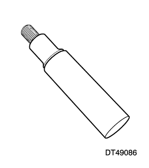
DT-49086
Bushing Remover/Installer
|
|
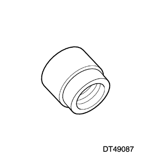
DT-49087
Bushing Remover
|

|
09924-17810
Fly Wheel Holder
|
|
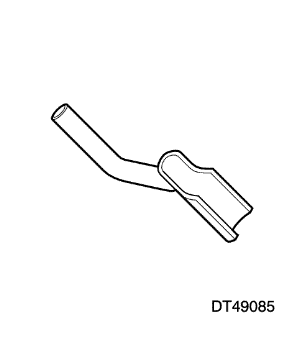
DT-49085
Bushing Remover/Installer
|
|
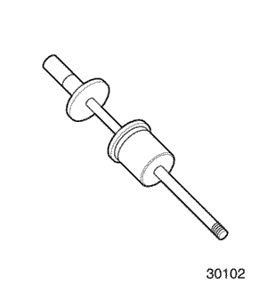
09930-30102
Sliding Shaft
|
|
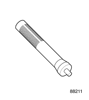
09943-88211
Bushing, Bearing Installer
|
|
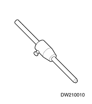
DW210-010
Clutch Center Guide
|
DIAGNOSIS
General Diagnosis
Condition
|
Probable Cause
|
Correction
|
|
Slipping Clutch
|
- Improper clutch cable adjustment.
|
|
- Worn or oily contamination on clutch disc surface.
|
|
- Worn or oily contamination on pressure plate, flywheel surface.
|
- Replace pressure plate, flywheel.
|
- Damaged or weakened diaphragm spring.
|
|
|
|
|
|
Dragging Clutch
|
- Improper clutch cable adjustment.
|
|
- Worn or weakened diaphragm spring.
|
|
- Worn or rusted splines of input shaft or clutch disc.
|
- Replace input shaft or clutch disc.
|
- Excessively wobbly clutch disc.
|
|
|
|
|
|
Fails to Release
|
- Bent or damaged clutch disc.
|
|
- Worn or rusted splines of input shaft or clutch disc.
|
- Replace input shaft or clutch disc.
|
- Improper operation of clutch release shaft.
|
- Replace clutch release shaft.
|
- Broken or damaged clutch cable.
|
|
|
Pedal Stays on Floor When Disengaged
|
- Interfered clutch release bearing.
|
- Lubricate and adjust clutch release bearing.
|
- Weakened diaphragm spring.
|
|
- Broken or damaged clutch cable.
|
|
|
Clutch Vibration
|
- Clutch facing with oily contamination.
|
|
- Release bearing slides unsmoothly on input shaft bearing retainer.
|
- Lubricate retainer release bearing.
|
- Wobbly clutch disc or poor facing contact.
|
|
- Loose clutch disc rivets.
|
|
- Weakened clutch disc torsion spring.
|
|
- Distorted pressure plate or flywheel surface.
|
- Replace pressure plate or flywheel.
|
- Weakened engine mounting or loosened installing bolt or nut.
|
- Retighten or replace mounting.
|
|
Clutch Noise
|
- Worn or broken release bearing.
|
|
- Worn input shaft bearing.
|
- Replace input shaft bearing.
|
|
|
|
- Pressure plate and diaphragm spring rattling.
|
|
- Improper clutch cable adjustment.
|
|
|
|
|
|
Grabbing Clutch
|
- Clutch disc facing with oily contamination.
|
|
- Excessively worn on clutch disc facing.
|
|
- Rivet head showing out of facing.
|
|
- Weakened clutch torsion spring.
|
|
Clutch Pedal Operation
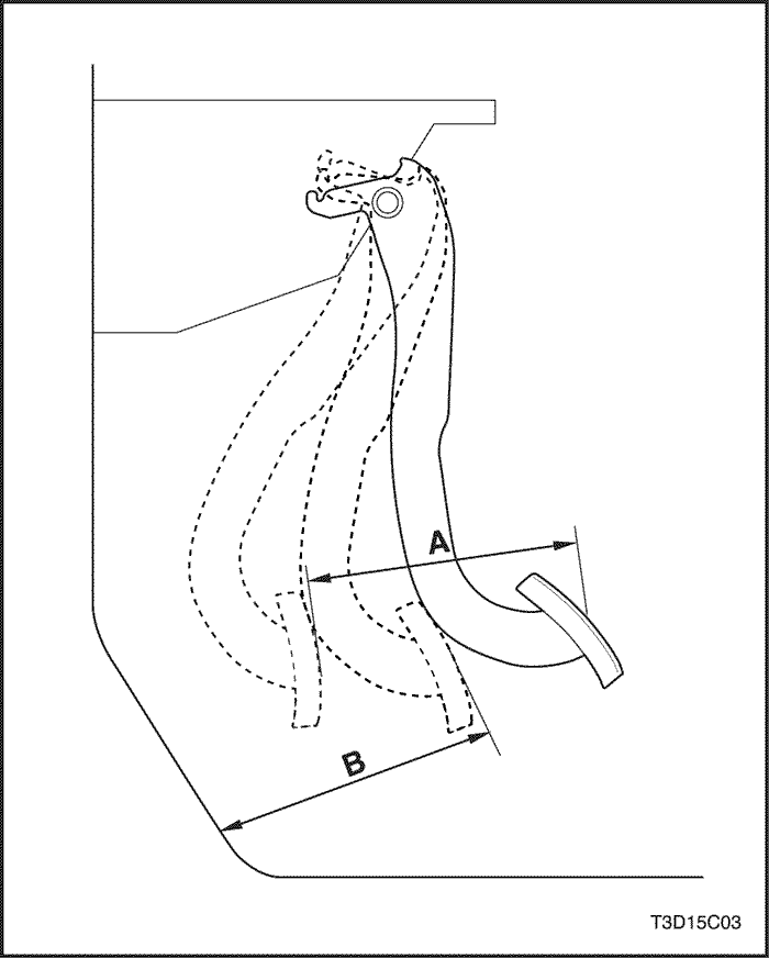
Clutch Pedal Free Travel
It is designed that there is no clutch pedal free travel.
Clutch pedal travel - A -
|
Pedal Travel
|
120 - 130 mm (4.7 - 5.1 in.)
|
Clearance between pedal and floor just before clutch connection - B -
After starting the engine, check if the clearance between pedal and floor is within specified range in condition of idling, lifting, parking brake and drawing out clutch pedal.
|
Clearance Between Pedal and Floor just Before Clutch
Connection
|
50 - 60 mm
(1.9 - 2.3 in.)
|
Clutch Cable Adjustment
If clutch connction/disconnection is operated unsmoothly, adjust the clutch cable by adjusting clutch cable adjustnut.
Clutch Cable
Check clutch cable and replace it any of followings exists.
- Excessively worn cable
- Loose cable
- Bent or distorted cable
- Damaged boot
- Worn end
COMPONENT LOCATOR
Clutch Components
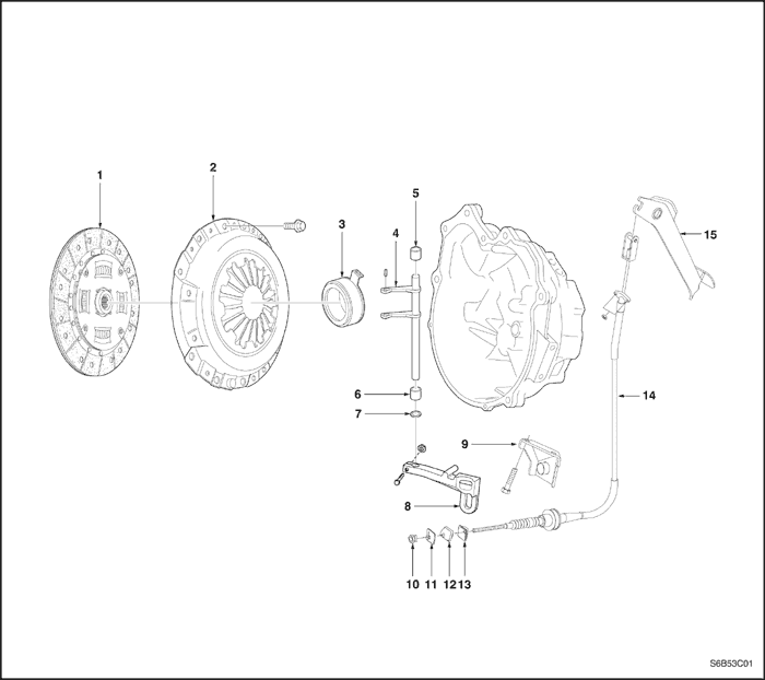
- Clutch Disc
- Pressure Plate
- Release Bearing
- Release Shaft
- Release Shaft Bushing (No.1)
- Release Shaft Bushing (No.2)
- Release Shaft Seal
- Release Arm
- Clutch Cable Bracket
- Clutch Cable Adjusting Nut
- Rear Clutch Release Plate
- Washer
- Front Clutch Release Plate
- Clutch Cable
- Clutch Pedal
MAINTENANCE AND REPAIR
ON-VEHICLE SERVICE
Pressure Plate and Clutch Disc
Tools Required
09924-17810 Flywheel Holder
DW210-010 Clutch Center Guide
Removal Procedure
- Remove the transaxle from the vehicle. Refer to Section 5B2, Five-Speed Manual Transaxle (Y4M HD).
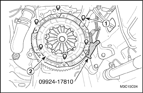
- Remove the pressure plate and the clutch disc.
- Fix the fly wheel using the fly wheel holder 09924-17810.
- Remove the pressure plate bolts (1).
- Remove the pressure plate and the clutch disc (2).
Inspection Procedure - Pressure Plate and Clutch Disc
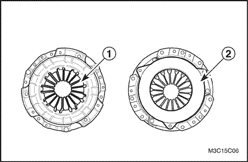
- Pressure plate inspection .
- Check the weak and damaged diaphragm spring (1).
- Check the polluted face by the oil, grease (2).
- Clutch disc inspection.
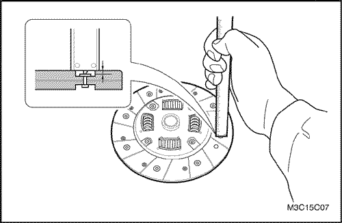
- Measure rivet head depth from clutch disc surface and replace if below limit.
-
- Unit : mm (in.)
|
Rivet Head Depth
|
Standard
|
Limit
|
|
1.2 (0.047)
|
0.5 (0.02)
|
- Replace the clutch disc if clutch disc surface is contaminated or clutch disc rivets are loosen.
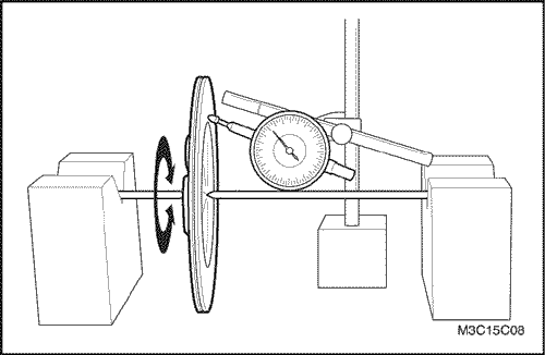
- Clutch disc runout in rotational direction inspection.
- Measure runout in rotational direction and replace if runout exceeds limit.
-
- Unit : mm (in.)
|
Disc Runout Limit in Rotational
Direction (Periphery)
|
1.0 (0.039)
|
Installation Procedure
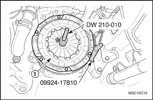
- Install the pressure plate and the clutch disc.
- Install the clutch disc.
- Install the pressure plate (1).
- Align the pressure plate and the clutch disc onto the flywheel using the clutch center guide DW210-010 and the flywheel holder 09924-17810.
- Install the pressure plate bolts.
Tighten
Tighten the bolts to 18-28 N•m (13-21 lb-ft).
- Install the transaxle into the vehicle. Refer to Section 5B2, Five-Speed Manual Transaxle (Y4M HD).
Clutch Release Bearing, Shaft and Bushing
Tools Required
DT-49085 Bushing Remover/Installer
DT-49086 Bushing Remover/Installer
DT-49087 Bushing Remover
09930-30102 Sliding Shaft
09943-88211 Bushing, Bearing Installer
Removal Procedure
- Remove the transaxle from the vehicle. Refer to Section 5B2, Five-Speed Manual Transaxle (Y4M HD).
- Remove the release arm. Refer to "Clutch Release Arm"
in this section.
- Remove the release bearing.
- Remove the release shaft and bushing.
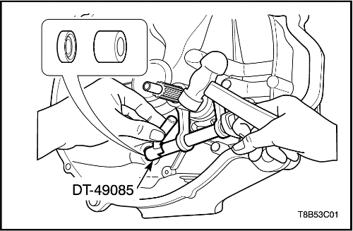
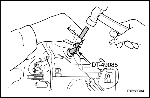
- Remove the bushing (No.2) and seal using the bushing remover/installer DT-49085 and hammer.
- Remove the release shaft.
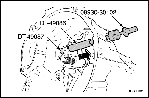
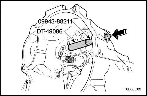
- Install the bushing remover/installer DT-49086 and the bushing remover DT-49087 to the bushing (No.1).
- Connect the sliding shaft 09930-30102 to the end of the bushing remover/installer DT-49086.
- Remove the bushing (No.1) by pulling.
Inspection Procedure - Release Bearing and Shaft
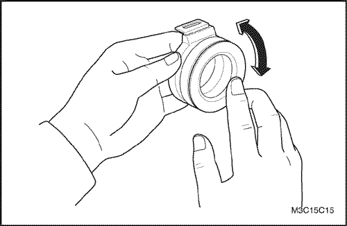
- Release bearing inspection.
- Check for noisy, worn and damaged release bearing.
- Check for a grabbing rotation of release bearing.
- Replace the release bearing if necessary.
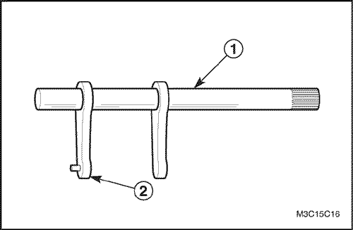
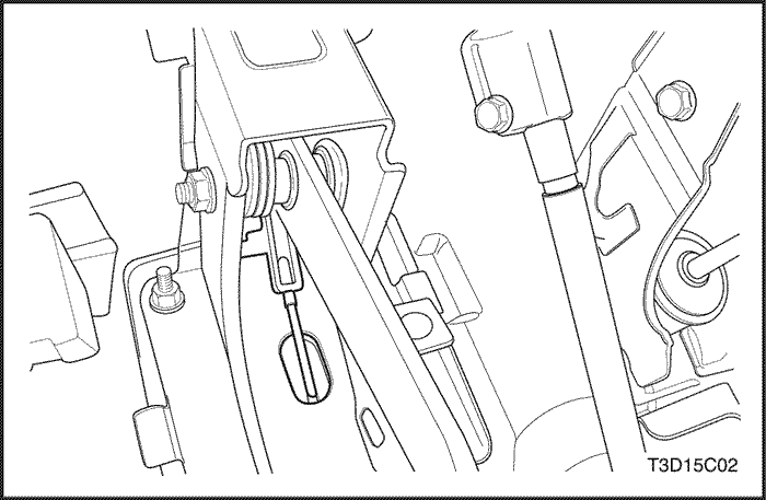
- Release shaft inspection.
- Check for a warped shaft (1).
- Check for a worn fork (2).
- Replace the shaft if necessary.
Installation Procedure
- Install the release shaft bushing (No.1) using the bushing remover/installer DT-49086, bushing, bearing installer 09943-88211 and a hammer.
- Install the release shaft.
- Coat the release shaft and bushing with grease.
- Install the release shaft bushing (No.2) and seal using the bushing remover/installer DT-49085 and a hammer.
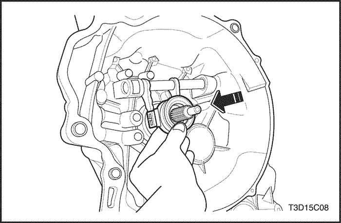
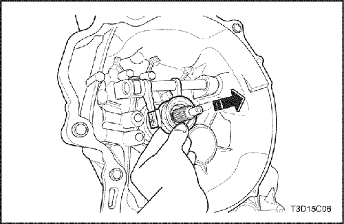
- Install the release bearing.
- Coat the spline of transaxle input shaft with multi-purpose grease.
- Coat the release bearing bore and the connecting of release shaft with multi-purpose grease.
- Install the release bearing.
- Install the release arm. Refer to "Clutch Release Arm"
in this section.
- Install the transaxle into the vehicle. Refer to Section 5B2, Five-Speed Manual Transaxle (Y4M HD).
Clutch Release Arm
Removal Procedure
- Disconnect the negative battery cable.
- Disconnect the clutch cable.
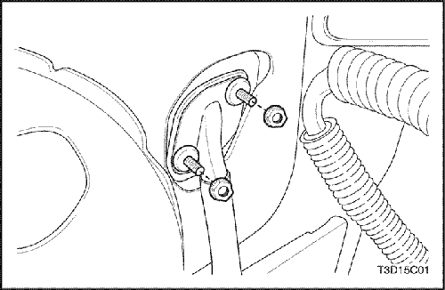
- Remove the adjusting nut (1).
- Remove the front clutch release plate, the washer and the rear clutch release plate(2).
- Disconnect the cable from the clutch release arm.
- Remove the clutch release arm.
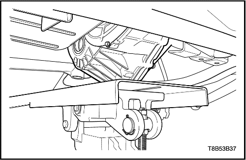
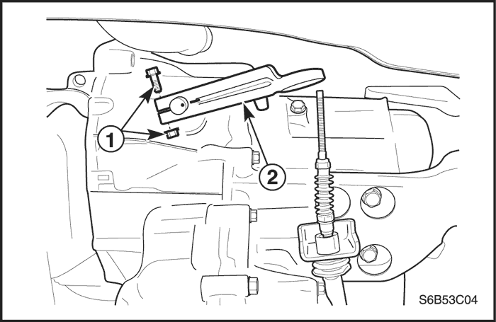
- Remove the bolt and nut (1).
- Remove the release arm (2).
Installation Procedure
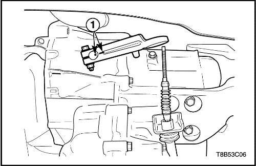
- Install the clutch release arm.
- Install the clutch release arm matching to punched mark (1).
Tighten
Tighten the bolt and nut to 10-16 N•m (7.5-12 lb-ft).
- Connect the clutch cable.
- Connect the cable to the clutch release arm.
- Install the front clutch release plate, the washer and the rear clutch release plate.
- Install the clable adjust nut.
- Adjust the clutch cable. Refer to "Diagnosis"
in this section.
- Connect the negative battery cable.
Clutch Cable
(Left-Hand Drive Shown, Right-Hand Drive Similar)
Removal Procedure
- Disconnect the negative battery cable.
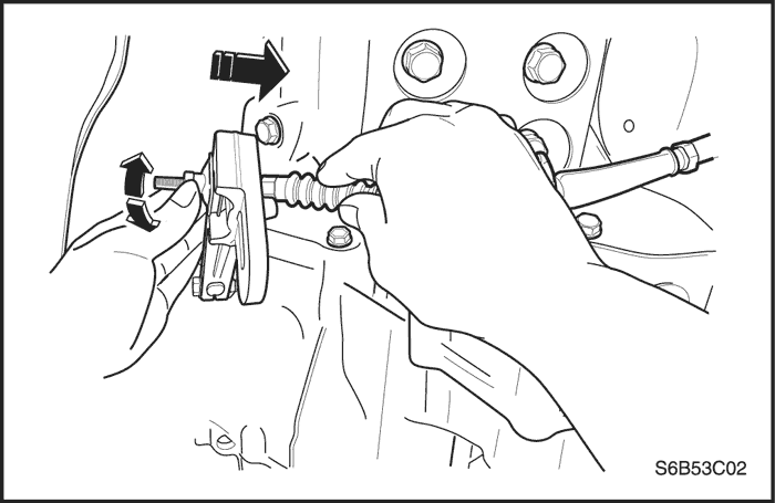
- Disconnect the clutch cable from the transaxle.
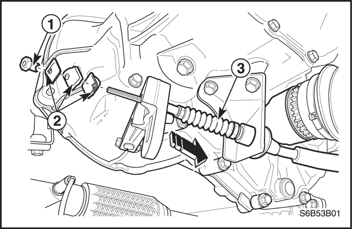
- Remove the adjusting nut (1).
- Remove the front clutch release plate, the washer and the rear clutch release plate (2).
- Pull and remove the cable from the transaxle mount hole (3).
- Disconnect the clutch cable from the pedal.
- Remove the clutch cable nuts and the cable.
Installation Procedure
- Install the clutch cable and the cable.
Tighten
Tighten the nuts to 9-13 N•m (80-115 lb-in).
- Connect the clutch cable to the pedal.
- Connect the clutch cable.
- Install the cable to the transaxle mount hole.
- Install the front clutch release plate, the washer and the rear clutch release plate.
- Install the cable adjust nut.
- Adjust the clutch cable. Refer to "Diagnosis"
in this section.
- Connect the negative battery cable.
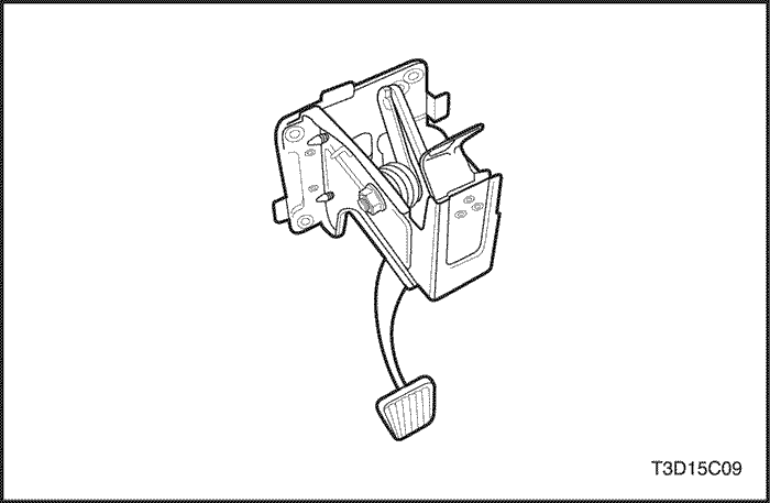
Clutch Pedal
Left-Hand Drive Shown, Right-Hand Drive Similar -
Removal Procedure
- Disconnect the clutch cable. Refer to "Clutch Cable"
in this section.
- Remove the clutch pedal.
- Release the pedal return spring.
- Remove the nut.
- Remove the shaft.
- Remove the clutch pedal.
- Remove the bushings.
- Remove the pedal return spring.
Installation Procedure
Notice : Be sure to coat the shaft, the bushings and the spring with grease.
- Install the pedal return spring.
- Install the bushings.
- Install the clutch pedal.
- Install the shaft.
- Install the nut.
- Fix the pedal return spring.
- Connect the clutch cable.
- Adjust the clutch cable. Refer to "Diagnosis"
in this section.
GENERAL DESCRIPTION AND SYSTEM OPERATION
Driving Members
The driving members consist of two flat surfaces machined to a smooth finish. One of these is the rear face of the engine flywheel, and the other is the pressure plate. The pressure plate is fitted into a steel cover, which is bolted to the flywheel.
Driven Members
The driven member is the clutch disc with a splined hub which is free to slide lengthwise along the splines of the input shaft, but which drives the input shaft through these same splines.
The driving and driven members are held in contact by spring pressure. This pressure is exerted by a diaphragm spring in the pressure plate assembly.
Operating Members
The clutch release system consists of the clutch pedal, the clutch release shaft, the clutch cable, the release arm and the release bearing. When pressure is applied to the clutch pedal, the clutch release shaft pushes against the release bearing by rotating. The bearing then pushes against the diaphragm spring in the pressure plate assembly, thereby releasing the clutch.


