Aveo |
||||||||
|
||||||||
|
Application
|
Description
|
|
Lubricant
|
Power Steering Fluid DEXRON® II D
|
|
Pressure
|
7,088 - 8,619 kPa (1,028 - 1,250 psi)
|
|
Type
|
Vane
|
|
Displacement
|
8.5 cc/rev
|
|
Capacity
|
0.66 Liter
|
|
Application
|
N•m
|
Lb-Ft
|
Lb-In
|
|
Air Cleaner Housing Bolts
|
12
|
-
|
106
|
|
Power Steering Pump Front Shackle Bolt
|
20
|
15
|
-
|
|
Power Steering Pump Rear Shackle Bolt
|
22
|
16
|
-
|
|
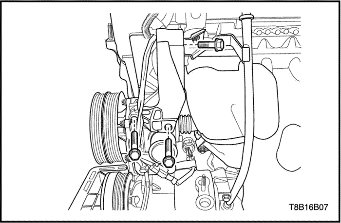
Power Steering Pump Bolt
|
22
|
16
|
-
|
|
Power Steering Pump Retaining Nut
|
25
|
18
|
-
|
|
Power Steering Pump Retaining Bolt
|
26
|
19
|
-
|
|
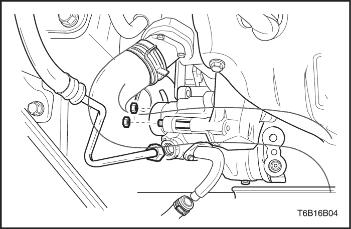
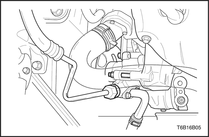
Power Steering Pump Pressure Line Union Nut
|
28
|
21
|
-
|
|
Power Steering Pump Mounting Bracket Bolt
|
25
|
18
|
-
|
|
Tension Pulley Securing Bolt
|
25
|
18
|
-
|
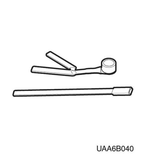 |
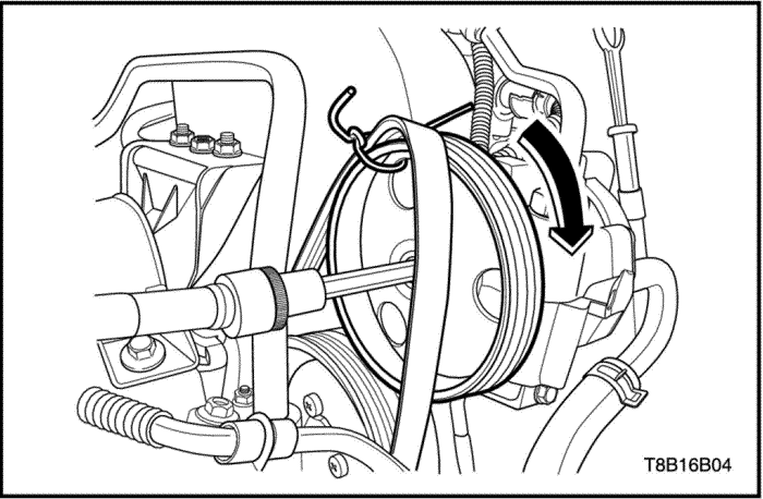
DW110-080
Serpentine Accessory Drive Belt Remover
|
|
Checks
|
Action
|
|
Check the power steering fluid level.
|
Fill the power steering fluid reservoir.
|
|
Check for air contamination in the power steering fluid.
|
Bleed the power steering system.
|
|
Check the power steering pump for internal leaks and overflow.
|
Replace the power steering pump.
|
|
Check the power steering pump housing and the soft plug for leaks.
|
Replace the power steering pump.
|
|
Checks
|
Action
|
|
Check the power steering pump flow control valve for sticking and improper operation.
|
Replace the power steering pump.
|
|
Check the power steering pump seals for wear.
|
Replace the power steering pump.
|
|
Check the pressure plate, the pump ring, the thrust plate, and the rotor for scores, cracks, or breaks.
|
Replace the power steering pump.
|
|
Check the vanes for sticking in the rotor slots.
|
Replace the power steering pump.
|
|
Check the power steering pump for internal leaks and overflow.
|
Replace the power steering pump.
|
|
Checks
|
Action
|
|
Check the pump hoses and the steering gear pipes for restricted flow.
|
Clean out the pipes and the hoses. Replace the pipes and the hoses as needed.
|
|
Check the pressure plate, the pump ring, the thrust plate, and the rotor for scores, cracks, or breaks.
|
Replace the power steering pump.
|
|
Check the power steering hose for contact with the body.
|
Secure the pump hose in a clamp away from the body.
|
|
Check the power steering fluid level.
|
Fill the power steering pump reservoir.
|
|
Checks
|
Action
|
|
Check for air contamination in the power steering fluid.
|
Bleed the power steering system.
|
|
Check the power steering hose for contact with the body.
|
Secure the pump hose in a clamp away from the body.
|
|
Check the power steering fluid level.
|
Fill the power steering pump reservoir.
|
|
Check the pump mounting for improper installation.
|
Tighten the power steering pump attachment bolts.
|
|
Checks
|
Action
|
|
Check the power steering pump flow control valve for damage.
|
Replace the power steering pump.
|
|
Checks
|
Action
|
|
Check the pressure plate and the vanes for scores.
|
Replace the power steering pump.
|
|
Check the pump shaft bearing for scores.
|
Replace the power steering pump.
|

| © Copyright Chevrolet Europe. All rights reserved |


