Aveo |
||||||||
|
||||||||
|
Application
|
Unit
|
Description
|
|
|
Compressor
|
-
|
V5
|
|
|
Receiver-Dryer
|
-
|
AL R/DRIER
|
|
|
Refrigerant
|
Type
|
-
|
R-134a System
|
|
Capacity
|
g
|
520±20 (RHD : 570±20)
|
|
|
Refrigerant Oil in A/C System
|
Type
|
-
|
UNION CARBIDE UCON 488 PAG OIL (ISU513)
|
|
Capacity
|
cc (ml)
|
200
|
|
|
A/C Cooling Capacity (Airflow rate 6.8 m/s)
|
Kcal/h
|
11,000-5%
|
|
|
Application
|
Unit
|
Description
|
|
|
Compressor
|
-
|
SP-10.4PK
|
|
|
Receiver-Dryer
|
-
|
AL R/DRIER
|
|
|
Refrigerant
|
Type
|
-
|
R-134a System
|
|
Capacity
|
g
|
520±20 (RHD : 570±20)
|
|
|
Refrigerant Oil in A/C System
|
Type
|
-
|
UNION CARBIDE RL897 PAG OIL (ISU105)
|
|
Capacity
|
cc (ml)
|
150
|
|
|
A/C Cooling Capacity (Airflow rate 6.8 m/s)
|
Kcal/h
|
11,000-5%
|
|
|
A/C Compressor ON/OFF Condition
|
Evaporator Thermistor Temperature
|
°C (°F)
|
Down below 2.0 °C (35.6 °F) : OFF
Go over 4.0 °C (39.2 °F) : ON
|
|
Application
|
N•m
|
lb-ft
|
lb-in
|
|
Air Cleaner Housing Assembly Retaining Bolts
|
12
|
-
|
106
|
|
Compressor Bracket Bolt
|
27
|
20
|
-
|
|
Control Assembly Retaining Screws
|
3
|
-
|
27
|
|
Expansion Valve Retaining Bolt
|
12
|
-
|
106
|
|
Heater/Air Distribution Case Assembly Retaining Screws
|
4
|
-
|
35
|
|
Liquid Evaporator Pipe Connector Block Retaining Nut
|
15
|
11
|
-
|
|
Liquid Pipe Connector Block to Condenser
|
14
|
10
|
-
|
|
Pressure Transducer
|
8
|
-
|
71
|
|
Refrigerant Discharge Hose Connector Block Bolt
|
16
|
12
|
-
|
|
Refrigerant Discharge Hose Support Clamp Bolt
|
8
|
-
|
71
|
|
Refrigerant Suction Hose and the Refrigerant Discharge hose to Compressor Connector Block Retaining Nut (V5 Compressor Only)
|
33
|
24
|
-
|
|
Refrigerant Suction Hose to Compressor Connector Block Retaining Bolt (SP10 Compressor Only)
|
33
|
24
|
-
|
|
Refrigerant Discharge Hose to Compressor Connector Block Retaining Bolt (SP10 Compressor Only)
|
33
|
24
|
-
|
|
Refrigerant Suction Hose Connector Block Retaining Nut
|
15
|
11
|
-
|
|
Condenser Mount Bolt
|
7-10
|
-
|
62-89
|
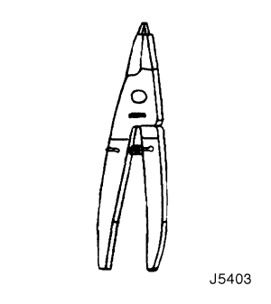 |
J-5403
Snap Ring Pliers
|
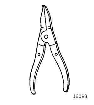 |
J-6083
Snap Ring Pliers
|
 |
J-8092
Driver Handle
|
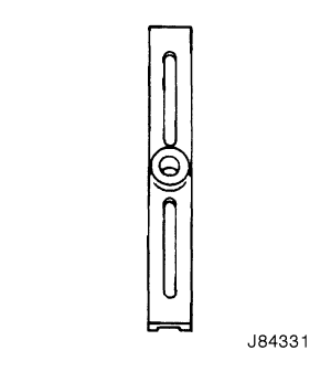 |
J-8433-1
Puller Crossbar
|
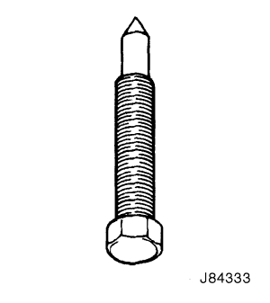 |
J-8433-3
Forcing Screw
|
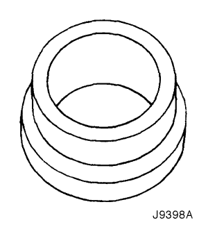 |
J-9398-A
Bearing Remover
|
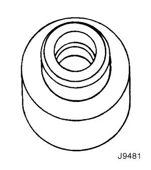 |
J-9481
Bearing Installer
|
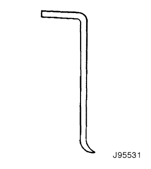 |
J-9553-1
O-Ring Remover
|
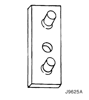 |
J-9625-A
Pressure Test Set
|
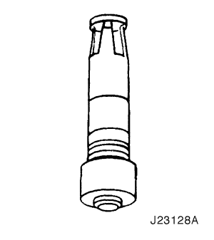 |
J-23128-A
Seal Seat Remover and Installer
|
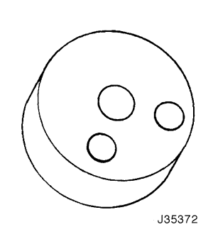 |
J-35372
Support Block
|
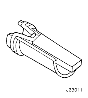 |
J-33011
O-Ring Installer
|
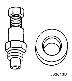 |
J-33013-B
Hub and Drive Plate Remover and Installer
|
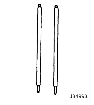 |
J-34993
Cylinder Alignment Rods
|
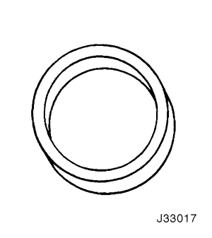 |
J-33017
Pulley Rotor and Bearing Assembly Installer
|
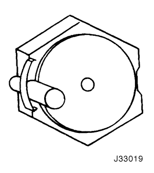 |
J-33019
Bearing Staking Tool Set Includes:
J-33019-1
Bearing Staking Guide
J-33019-2
Bearing Staking Pin
|
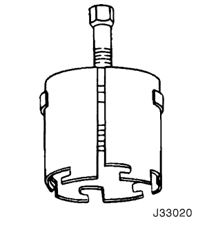 |
J-33020
Pulley Puller
|
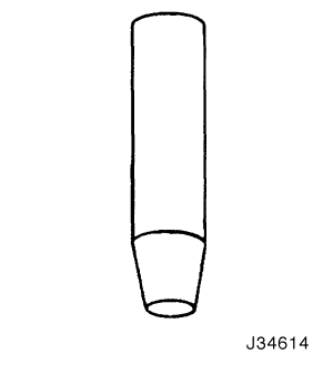 |
J-34614
Shaft Seal Protector
|
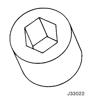 |
J-33022
Shaft Nut Socket
|
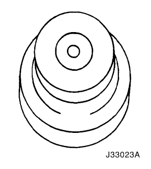 |
J-33023-A
Puller Pilot
|
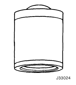 |
J-33024
Clutch Coil Installer Adapter
|
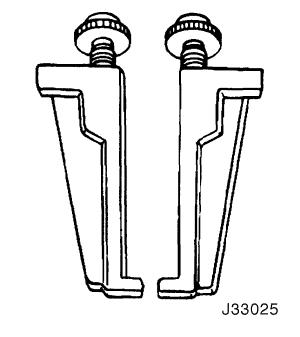 |
J-33025
Clutch Coil Puller Legs
|
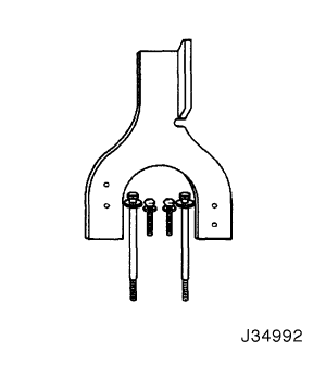 |
J-34992
Compressor Holding Fixture
|
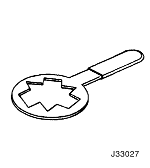 |
J-33027
Clutch Hub Holding Tool
|
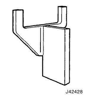 |
J-42428
Compressor Holding Fixture
|
 |
DW-610-010
Clutch Hub Holding Tool (for SP10 compressor)
|
RELATIVE HUMIDITY ( % )
|
AMBIENT AIR TEMPERATURE
|
LOW SIDE PRESSURE
|
ENGINE SPEED (RPM)
|
CENTER DUCT AIR TEMPERATURE
|
HIGH SIDE PRESSURE
|
||||
.
|
°C
|
°F
|
Psi
|
Kpa
|
.
|
°C
|
°F
|
Psi
|
Kpa
|
|
.
|
21
|
70
|
25
|
170
|
.
|
4
|
39
|
162
|
1117
|
|
20
|
27
|
81
|
26
|
180
|
2000
|
6
|
43
|
210
|
1448
|
|
.
|
32
|
90
|
30
|
210
|
.
|
8
|
46
|
263
|
1810
|
|
.
|
38
|
100
|
36
|
250
|
.
|
12
|
54
|
325
|
2240
|
|
.
|
21
|
70
|
25
|
170
|
.
|
5
|
41
|
165
|
1138
|
|
30
|
27
|
81
|
26
|
180
|
2000
|
7
|
45
|
225
|
1551
|
|
.
|
32
|
90
|
32
|
220
|
.
|
10
|
50
|
278
|
1920
|
|
.
|
38
|
100
|
39
|
270
|
.
|
15
|
59
|
336
|
2320
|
|
.
|
21
|
70
|
25
|
170
|
.
|
6
|
43
|
176
|
1214
|
|
40
|
27
|
81
|
28
|
190
|
2000
|
8
|
46
|
235
|
1620
|
|
.
|
32
|
90
|
33
|
230
|
.
|
11
|
52
|
286
|
1970
|
|
.
|
38
|
100
|
42
|
290
|
.
|
16
|
61
|
342
|
2360
|
|
.
|
21
|
70
|
25
|
170
|
.
|
7
|
45
|
190
|
1310
|
|
50
|
27
|
81
|
29
|
200
|
2000
|
9
|
48
|
238
|
1640
|
|
.
|
32
|
90
|
36
|
250
|
.
|
13
|
55
|
292
|
2010
|
|
.
|
38
|
100
|
46
|
320
|
.
|
18
|
64
|
364
|
2510
|
|
.
|
21
|
70
|
25
|
170
|
.
|
8
|
46
|
195
|
1345
|
|
60
|
27
|
81
|
29
|
200
|
2000
|
9
|
48
|
244
|
1680
|
|
.
|
32
|
90
|
39
|
270
|
.
|
14
|
57
|
312
|
2150
|
|
.
|
38
|
100
|
52
|
360
|
.
|
21
|
70
|
380
|
2620
|
|
.
|
21
|
70
|
26
|
180
|
.
|
8
|
46
|
200
|
1379
|
|
70
|
27
|
81
|
33
|
230
|
2000
|
10
|
50
|
249
|
1720
|
|
.
|
32
|
90
|
42
|
290
|
.
|
15
|
59
|
318
|
2190
|
|
.
|
38
|
100
|
54
|
370
|
.
|
21
|
70
|
384
|
2650
|
|
.
|
21
|
70
|
26
|
180
|
.
|
9
|
48
|
213
|
1469
|
|
80
|
27
|
81
|
33
|
230
|
2000
|
12
|
54
|
254
|
1750
|
|
.
|
32
|
90
|
46
|
320
|
.
|
17
|
63
|
325
|
2240
|
|
.
|
21
|
70
|
26
|
180
|
.
|
9
|
48
|
225
|
1551
|
|
90
|
27
|
81
|
35
|
240
|
2000
|
13
|
55
|
261
|
1800
|
|
.
|
32
|
90
|
49
|
340
|
.
|
19
|
66
|
341
|
2350
|
Air Mode
|
Ambient Air Temperature °C (°F)
|
Low Side Pressure kPa (psi)
|
Engine Speed (RPM)
|
Center Duct Air Temperature °C (°F)
|
High Side Pressure kPa (psi)
|
|
Recirculation Mode
|
.
|
270 (39)
|
880
|
15.7 (60.3)
|
1924 (279)
|
|
38 (100)
|
116 (17)
|
1900
|
4.2~4.9 (39.6~40.8)
|
1238 (180)
|
|
|
.
|
131 (19)
|
2400
|
4.2~7.1 (39.6~44.8)
|
1170 (170)
|
|
|
.
|
108 (16)
|
3300
|
6.4~7.1 (43.5~44.8)
|
1072 (155)
|
|
|
Outside Air Mode
|
.
|
441 (64)
|
880
|
26.3 (79.3)
|
2138 (310)
|
|
38 (100)
|
253 (37)
|
1900
|
16.7 (62.1)
|
1436 (208)
|
|
|
.
|
229 (33)
|
2400
|
15.4 (59.7)
|
1376 (200)
|
|
|
.
|
200 (29)
|
3300
|
14.6 (58.3)
|
1390 (202)
|
|
Temperature °C (°F)*
|
Pressure kPa (psi)*
|
Temperature °C (°F)*
|
Pressure kPa (psi)*
|
|
-8.89 (16)
|
105.70 (15.33)
|
37.78 (100)
|
856.84 (124.27)
|
|
-7.78 (18)
|
114.87 (16.66)
|
38.89 (102)
|
886.56 (128.58)
|
|
-6.67 (20)
|
124.32 (18.03)
|
40.00 (104)
|
916.35 (132.98)
|
|
-5.56 (22)
|
134.11 (19.45)
|
41.11 (106)
|
947.92 (137.48)
|
|
-4.44 (24)
|
144.24 (20.92)
|
42.22 (108)
|
979.64 (142.08)
|
|
-3.33 (26)
|
154.65 (22.43)
|
43.33 (110)
|
1012.11 (146.79)
|
|
-2.22 (28)
|
165.48 (24.00)
|
44.44 (112)
|
1045.21 (151.59)
|
|
-1.11 (30)
|
176.65 (25.62)
|
45.56 (114)
|
1079.14 (156.51)
|
|
0.00 (32)
|
188.16 (27.29)
|
46.67 (116)
|
1113.75 (161.53)
|
|
1.11 (34)
|
200.02 (29.01)
|
47.78 (118)
|
1149.12 (166.66)
|
|
2.22 (36)
|
212.30 (30.79)
|
48.89 (120)
|
1185.18 (171.89)
|
|
3.33 (38)
|
224.98 (32.63)
|
50.00 (122)
|
1222.07 (177.24)
|
|
4.44 (40)
|
238.08 (34.53)
|
51.11 (124)
|
1259.72 (182.70)
|
|
7.22 (45)
|
272.49 (39.52)
|
52.22 (126)
|
1298.12 (188.27)
|
|
10.00 (50)
|
309.58 (44.90)
|
53.33 (128)
|
1337.35 (193.96)
|
|
12.77 (55)
|
349.51 (50.69)
|
54.44 (130)
|
1377.35 (199.76)
|
|
15.56 (60)
|
392.33 (56.90)
|
57.22 (135)
|
1480.91 (214.78)
|
|
18.33 (65)
|
438.18 (63.55)
|
60.00 (140)
|
1589.57 (230.54)
|
|
21.11 (70)
|
487.27 (70.67)
|
62.78 (145)
|
1703.62 (247.08)
|
|
23.89 (75)
|
539.67 (78.27)
|
65.56 (150)
|
1823.04 (264.40)
|
|
26.67 (80)
|
609.38 (88.38)
|
68.33 (155)
|
1948.04 (282.53)
|
|
29.44 (85)
|
655.09 (95.01)
|
71.11 (160)
|
2078.77 (301.49)
|
|
32.22 (90)
|
718.39 (104.19)
|
73.89 (165)
|
2215.29 (321.29)
|
|
35.00 (95)
|
785.61 (113.94)
|
76.67 (170)
|
2357.81 (341.96)
|
| Step | Action | Value(s) | Yes | No |
| 1 |
Can you verify the customer complaint?
|
-
|
Go to Step 2
|
System OK
|
| 2 |
Is the discharge air temperature normal?
|
At least 7°C (13°F) below ambient air temperature
|
System OK
|
Go to Step 3
|
| 3 |
Are both pressures within the value specified?
|
69-345 kPa
(10-50 psi)
|
Go to Step 4
|
Go to Step 5
|
| 4 |
Are both pressures above the value specified?
|
345 kPa
(50 psi)
|
Go to Step 7
|
-
|
| 5 |
Observe the two pressure gauges.
Are both pressures below the value specified?
|
69 kPa
(10 psi)
|
Go to Step 6
|
Go to Step 7
|
| 6 |
Are both pressures above the value specified?
|
345 kPa
(50 psi)
|
Go to Step 7
|
-
|
| 7 |
Does the A/C compressor clutch engage?
|
-
|
Go to Step 8
|
Go to Step 10
|
| 8 |
Do you hear a loud knocking noise?
|
-
|
Go to Step 9
|
Go to Step 13
|
| 9 |
Is the compressor running normally?
|
-
|
Go to Step 13
|
-
|
| 10 |
Does the A/C clutch engage?
|
-
|
Go to Step 11
|
Go to Step 12
|
| 11 |
Repair the electrical circuit to the A/C compressor clutch coil.
Does the A/C clutch engage?
|
-
|
Go to Step 8
|
-
|
| 12 |
Replace the A/C compressor clutch coil.
Does the A/C clutch engage?
|
-
|
Go to Step 8
|
-
|
| 13 |
Important : Perform this test under garage conditions; 21-32°C (70-90°F) and no sun load. Follow this test carefully for accurate results.
Is there a noticeable difference in the temperature of the evaporator inlet and outlet pipes?
|
-
|
Go to Step 15
|
Go to Step 14
|
| 14 |
Is the discharge temperature normal?
|
At least 7°C (13°F) below ambient air temperature
|
Go to Step 15
|
Go to Step 13
|
| 15 |
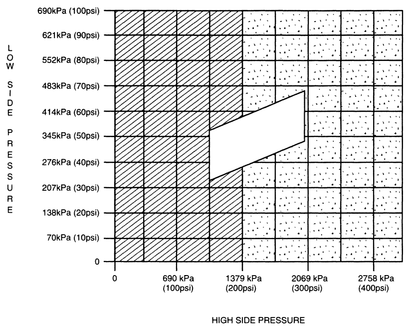
Do the low and the high side pressures intersect in the white area of the chart?
|
-
|
System OK
|
Go to Step 16
|
| 16 |
Check the high-side and low-side pressures.
Do the low- and the high-side pressures intersect in the gray area of the chart?
|
-
|
Go to Step 17
|
Go to Step 20
|
| 17 |
Feel the liquid pipe between the condenser and the expansion valve.
Is the pipe cold?
|
-
|
Go to Step 18
|
Go to Step 19
|
| 18 |
Is the pipe temperature normal now?
|
-
|
Go to Step 13
|
-
|
| 19 |
Is the system leak tight?
|
-
|
Go to Step 13
|
-
|
| 20 |
Observe the readings on the pressure gauges.
Are the A/C compressor high- and the low-side pressures within the specified value of each other?
|
207 kPa (30 psi)
|
Go to Step 21
|
Go to Step 26
|
| 21 |
Are the A/C compressor high- and the low-side pressures within the specified value of each other?
|
207 kPa
(30 psi)
|
Go to Step 22
|
Go to Step 13
|
| 22 |
Observe the pressure rise on both gauges and the temperatures of both the compressor suction pipe and the discharge pipe.
Is the pressure rise on both gauges slow and the suction pipe warm with the discharge pipe very hot?
|
-
|
Go to Step 25
|
Go to Step 23
|
| 23 |
Can you turn the clutch driver freely by hand?
|
-
|
Go to Step 25
|
Go to Step 24
|
| 24 |
Does the low-side pressure rise rapidly?
|
-
|
Go to Step 32
|
Go to Step 25
|
| 25 |
Is the compressor functioning normally?
|
-
|
Go to Step 13
|
-
|
| 26 |
Check the low-side pressure.
Is the low-side pressure within the specified value?
|
172-241 kPa (25-35 psi)
|
Go to Step 27
|
Go to Step 32
|
| 27 |
Feel the high-side pipe leading up to the expansion valve connecting block.
Is the pipe cold before the connecting block?
|
-
|
Go to Step 28
|
Go to Step 29
|
| 28 |
Is the pipe performing normally?
|
-
|
Go to Step 13
|
-
|
| 29 |
Add the specified amount of refrigerant to the A/C system.
Does the cooling performance improve?
|
0.40 kg
(14 ounces)
|
Go to Step 30
|
Go to Step 31
|
| 30 |
Is the system leak free?
|
-
|
Go to Step 13
|
-
|
| 31 |
Is the system leak free?
|
-
|
Go to Step 13
|
-
|
| 32 |
Important : Perform this test exactly as described to obtain accurate results.
Is the low-side pressure within the specified value?
|
172-241 kPa
(25-35 psi)
|
Go to Step 13
|
Go to Step 33
|
| 33 |
Is the system free from leaks?
|
-
|
Go to Step 13
|
-
|
| Step | Action | Value(s) | Yes | No |
| 1 |
Can you verify the customer complaint?
|
-
|
Go to Step 2
|
System OK
|
| 2 |
Is the A/C system operation normal?
|
-
|
System OK
|
Go to Step 3
|
| 3 |
Are both pressures within the value specified?
|
Low Side Pressure: 200 kPa (29 Psi)
High Side Pressure: 1,500 kPa (217.5 Psi)
|
Go to Step 8
|
Go to Step 6
|
| 4 |
Are both pressures above the specified value?
|
↑
|
Go to Step 5
|
-
|
| 5 |
Are both pressures within the specified value?
|
↑
|
Go to Step 8
|
Go to -
|
| 6 |
Are both pressures below the specified value?
|
↑
|
Go to Step 7
|
Go to Step 4
|
| 7 |
Are both pressure within the specified value?
|
↑
|
Go to Step 8
|
-
|
| 8 |
Does the A/C compressor clutch engage?
|
-
|
Go to Step 9
|
Go to Step 11
|
| 9 |
Do you hear a loud knocking noise?
|
-
|
Go to Step 10
|
Go to Step 14
|
| 10 |
Is the repair complete?
|
-
|
Go to Step 14
|
-
|
| 11 |
Does the A/C clutch engage?
|
-
|
Go to Step 12
|
Go to Step 13
|
| 12 |
Repair the electrical circuit to the A/C compressor clutch coil.
Does the A/C clutch engage?
|
-
|
Go to Step 20
|
Go to Step 13
|
| 13 |
Replace the A/C compressor clutch coil.
Does the A/C clutch engage?
|
-
|
Go to Step 9
|
Go to Step 10
|
| 14 |
Important : Perform this test under garage conditions; 21-32°C (70-90°F) and no sun load. Follow this test carefully for accurate results.
Is there a noticeable difference in the temperature of the evaporator inlet and outlet pipes?
|
-
|
Go to Step 16
|
Go to Step 15
|
| 15 |
Is the discharge temperature normal?
|
-
|
Go to Step 16
|
Go to Step 18
|
| 16 |
Feel the liquid pipe between the condenser and the expansion valve.
Is the pipe cold?
|
-
|
Go to Step 19
|
Go to Step 17
|
| 17 |
Is the repair complete?
|
-
|
System OK
|
-
|
| 18 |
Is the repair complete?
|
-
|
System OK
|
-
|
| 19 |
Are the A/C compressor high and the low side pressures within the specified value of each other?
|
Low Side Pressure: 200 kPa (29 psi)
High Side Pressure: 1,500 kPa (217.5 psi)
|
System OK
|
Go to Step 22
|
| 20 |
Can you turn the clutch driver freely by hand?
|
-
|
Go to Step 23
|
Go to Step 21
|
| 21 |
Is the repair complete?
|
-
|
System OK
|
-
|
| 22 |
Does the cooling performance improve?
|
-
|
System OK
|
Go to Step 23
|
| 23 |
Is the repair complete?
|
-
|
System OK
|
-
|
|
Test Results
|
Related Symptioms
|
Probable Cause
|
Remedy
|
|
Discharge (high) pressure abnormally high
|
After stopping the compressor, the pressure drops about 299 kPa (28 psig) quickly, then falls gradually.
|
Air in the system.
|
Recover, evacuate and recharge the system with the specified amount of refrigerant.
|
|
The condenser is excessively hot.
|
Excessive refrigerant in the system.
|
Recover, evacuate and recharge the system with the specified amount of refrigerant.
|
|
|
Reduced or no airflow through the condenser.
|
Condenser or the radiator fins are clogged.
|
Clean the condenser or the radiator fins.
|
|
|
.
|
Condenser or the radiator fan is not working properly.
|
Check the voltage and the fan rpm.
Check the fan direction.
|
|
|
Line to the condenser is excessively hot.
|
Restricted flow of refrigerant in the system.
|
Locate and repair the restriction.
|
|
|
Discharge pressure abnormally low
|
The condenser is not hot.
|
Insufficient refrigerant in the system.
|
Check the system for a leak.
Charge the system.
|
|
High and low pressures are balanced soon after stopping the compressor.
|
Faulty compressor pressure relief valve.
|
Repair or replace the compressor.
|
|
|
Low-side pressure is higher than normal.
|
Faulty compressor seal.
|
.
|
|
|
The outlet of the expansion valve is not frosted.
|
Faulty expansion valve.
|
Replace the expansion valve.
|
|
|
Low pressure gauge indicates vacuum.
|
Moisture in the system.
|
Recover, evacuate, and recharge the system.
|
|
|
Suction (low) pressure abnormally low
|
Condenser is not hot.
|
Insufficient refrigerant in the system.
|
Repair the leaks.
Recover, evacuate, and recharge the system.
|
|
The expansion valve is not frosted and the lowpressure line is not cold.
|
Faulty expansion valve.
|
Replace the expansion valve.
|
|
|
Low-Pressure gauge indicates a vacuum.
|
Frozen expansion valve.
|
.
|
|
|
Discharge temperature is low and the airflow from the vents is restricted.
|
Evaporator is frozen.
|
Clear the restricted evaporator case drain.
|
|
|
The expansion valve is frosted.
|
Expansion valve is clogged.
|
Clean or replace the expansion valve.
|
|
|
The receiver-dryer outlet is cool and the inlet is warm.
|
Receiver-dryer is clogged.
|
Replace the receiver-dryer.
|
|
|
Suction pressure abnormally high
|
Low-pressure hose and check joint are cooler than the temperature around the evaporator.
|
Expansion valve is opened for too long.
|
Replace the expansion valve.
|
|
.
|
Capillary tube is loose.
|
.
|
|
|
Suction pressure abnormally high
|
Suction pressure is lowered when the condenser is cooled by water.
|
Excessive refrigerant in the system.
|
Recover, evacuate, and recharge the system.
|
|
High and low pressure are equalized as soon as the compressor is stopped and both gauges fluctuate while the compressor is running.
|
Faulty gasket.
|
Repair or replace the compressor.
|
|
|
.
|
Faulty high-pressure valve. (V5 compressor only)
|
.
|
|
|
.
|
Foreign particles stuck in the high-pressure valve. (V5 compressor only)
|
.
|
|
|
Suction and discharge pressure abnormally high
|
Reduced airflow through the condenser.
|
Clogged condenser or radiator fins.
|
Clean the condenser and the radiator.
|
|
.
|
Radiator cooling fans working improperly.
|
Check the voltage and the radiator cooling fan rpm. Check the fan direction.
|
|
|
Condenser is excessively hot.
|
Excessive refrigerant in the system.
|
Recover, evacuate, and recharge the system.
|
|
|
Suction and discharge pressure abnormally low
|
Low-pressure hose and metal end areas are cooler than the evaporator.
|
Clogged or kinked low-pressure hose.
|
Repair or replace the low-pressure hose.
|
|
Temperature around the expansion valve is low compared to that around the receiver-dryer.
|
Clogged high-pressure line.
|
Repair or replace the high-pressure line.
|
|
|
Refrigerant leaks
|
The compressor clutch is dirty.
|
Leaking compressor shaft seal.
|
Repair or replace the compressor.
|
|
The compressor bolts are dirty.
|
Leaking around a compressor housing bolt.
|
Tighten the bolt(s) or replace the compressor.
|
|
|
The compressor gasket is wet with oil.
|
Leaking compressor gasket.
|
Repair or replace the compressor.
|
| © Copyright Chevrolet Europe. All rights reserved |


