UNIT REPAIR
V5 AIR CONDITIONING COMPRESSOR OVERHAUL


Clutch Plate and Hub Assembly
Tools Required
J-33013-B Hub and Drive Plate Remover /Installer
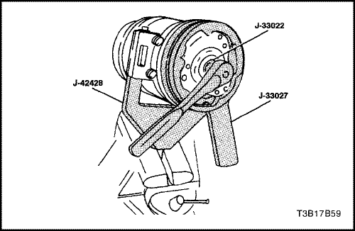
J-33022 Shaft Nut Socket
J-33027 Clutch Hub Holding Tool
J-34992 Compressor Holding Fixture
Disassembly Procedure
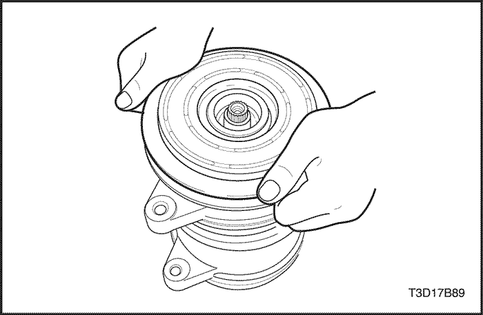
- Remove the compressor. Refer to "Compressor" in this section.
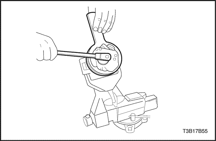
- Install the compressor holding fixture J-34992 to the compressor and hold the compressor holding fixture using a bench vise.
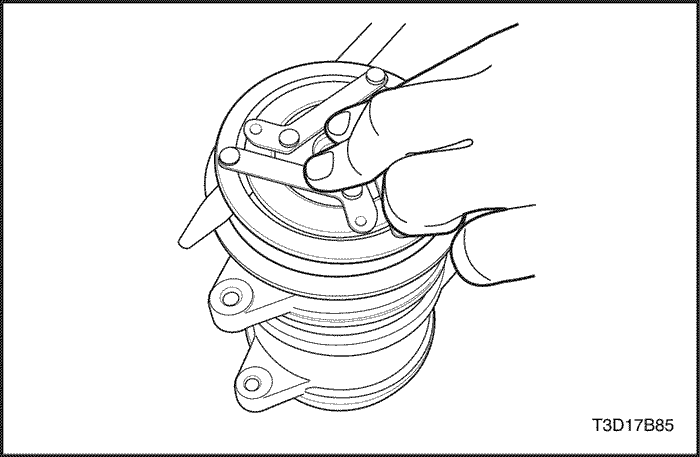
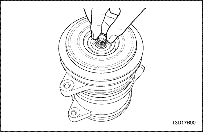
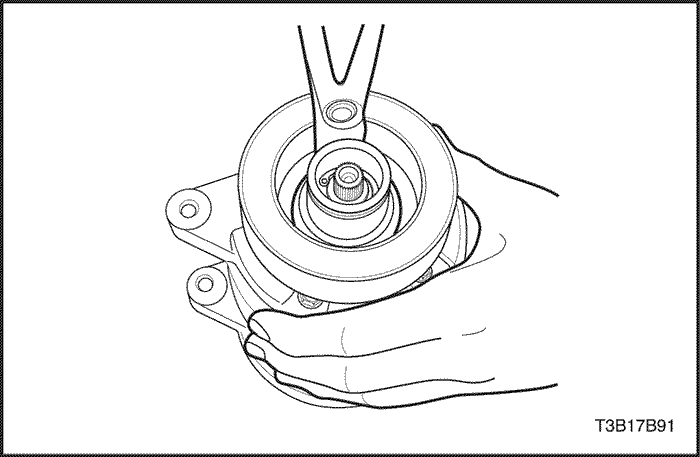
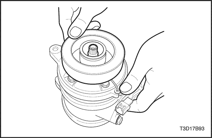
- Use the clutch hub holding tool J-33027 to keep the clutch drive plate and the hub assembly from turning.Remove the shaft nut.
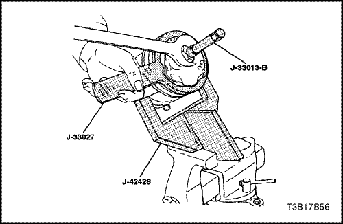
- Thread the hub and drive plate remover J-33013-B into the hub. Hold the body of the remover with a wrench and turn the center screw into the remover body to remove the clutch drive plate and hub assembly.
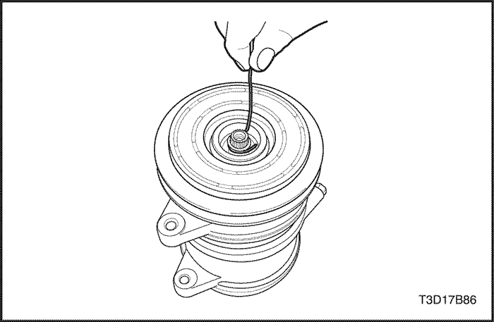
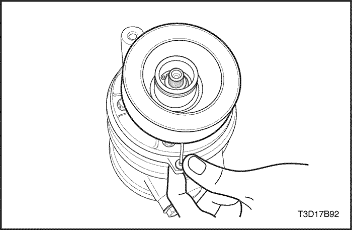
- Remove the clutch hub key. Retain the key for assembly.
Assembly Procedure
- Install the clutch hub key into the hub keyway. Allow the key to project approximately 3.2 mm (1/8 inch) out of the keyway. The hub key is curved slightly to provide an interference fit in the hub key groove.
- Be sure the frictional surface of the clutch plate and the pulley rotor are clean before installing the clutch drive plate and the hub assembly.
Notice : Do not drive or pound on the clutch hub or the shaft. Internal damage to compressor may result.
- Align the clutch hub key with the shaft keyway. Place the clutch drive plate and hub assembly onto the compressor shaft.
- Remove the hub and drive plate remover/installer J-33013-B center bolt and reverse the body direction on the center bolt. The body of the hub and drive plate remover/installer J-33013-B should be backed off sufficiently to allow the center bolt to be threaded onto the end of the compressor shaft.
Important : If the center bolt is threaded fully onto the end of the compressor shaft, or if the body of the hub and drive plate remover/installer J-33013-B is held and the center bolt is rotated, the key will wedge and could break the clutch drive plate and the hub assembly.
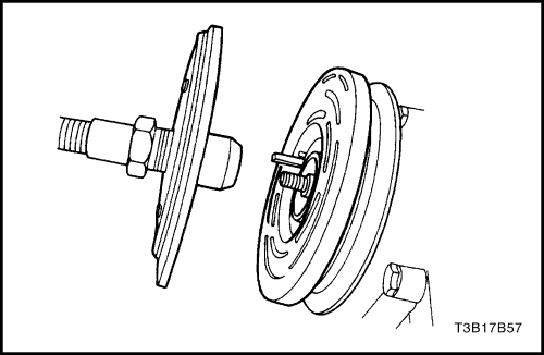
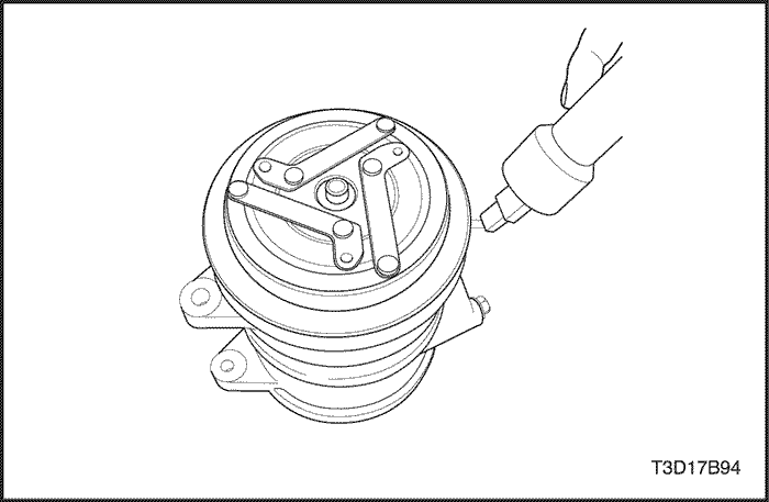
- Install the hub and drive plate remover/installer J-33013-B and the bearing onto the clutch drive plate. Thread the center bolt onto the compressor shaft.
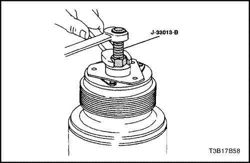
- Hold the center bolt with a wrench. Tighten the hex portion of the hub and drive plate remover/installer J-33013-B body to press the hub onto the shaft. Tighten the body several turns.
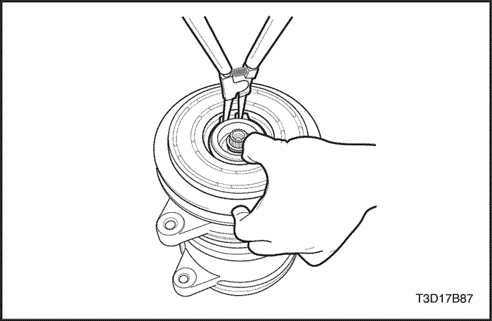
- Remove the hub and drive plate remover/installer J-33013-B and check to see that the clutch hub key is still in place in the keyway before installing the clutch drive plate and the hub assembly to its final position. The air gap between frictional surfaces of the clutch drive plate and the clutch pulley rotor should be 0.38 to 0.64 mm (0.015 to 0.025 inch.).
- Remove the hub and drive plate remover/installer J-33013-B. Check for proper positioning of the clutch hub key. It should be even or slightly above the clutch hub.
- Install the shaft nut. Hold the clutch drive plate and the hub assembly with the clutch hub holding tool J-33027. Use the shaft nut socket J-33022 and tighten the nut against the compressor shaft shoulder.
Tighten
Tighten the clutch plate and hub assembly nut to 17 N•m (13 lb-ft).
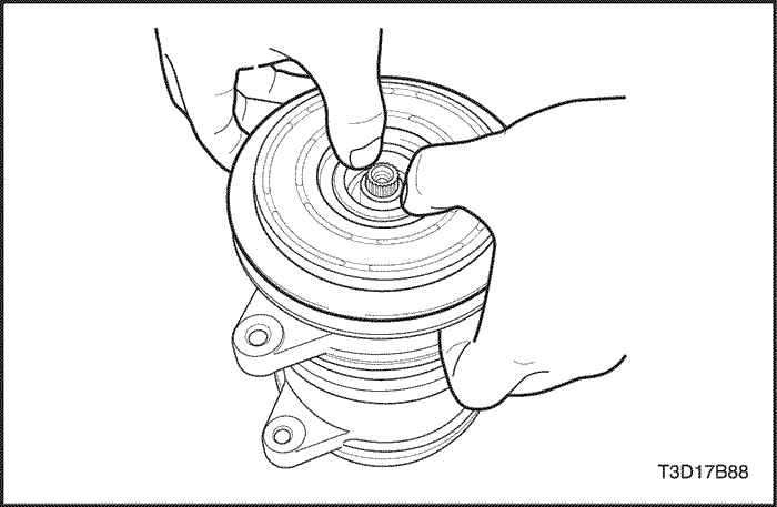
- Spin the pulley rotor by hand to verify that the pulley is not rubbing the clutch drive plate.
- Remove the compressor from the bend vise and remove the J-42428 compressor holding fixture on the compressor.
- Install the compressor. Refer to "Compressor" in this section.
Clutch Rotor and Bearing
Tools Required
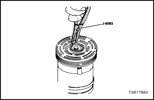
J-6083 Snap Ring Pliers
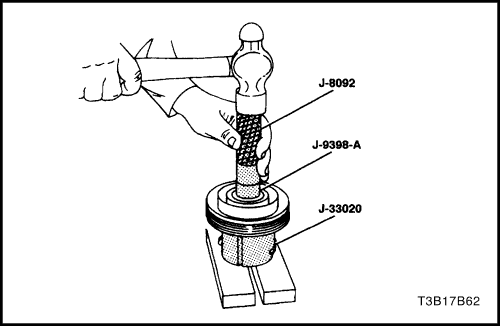
J-8092 Driver Handle
J-8433-1 Puller Crossbar
J-8433-3 Forcing Screw
J-9398-A Bearing Remover
J-9481 Bearing Installer
J-33017 Pulley Rotor and Bearing Assembly Installer
J-33019 Bearing Staking Tool Set
Includes: J-33019-1 Bearing Staking Guide
J-019-2 Bearing Staking Pin
J-33020 Pulley Puller
J-33023-A Puller Pilot
J-34992 Compressor Holding Fixture
J-42428 Compressor Holding Fixture
Disassembly Procedure
- Disconnect the negative battery cable.
- Recover the refrigerant. Refer to "Discharging, Adding Oil, Evacuating, and Charging for A/C System" in this section.
- Remove the compressor. Refer to "Compressor" in this section.
- Remove the clutch drive plate and hub assembly. Refer to "Clutch Plate and Hub Assembly" in this section.
- Remove the pulley rotor and the bearing assembly retaining ring using the snap ring pliers J-6083.
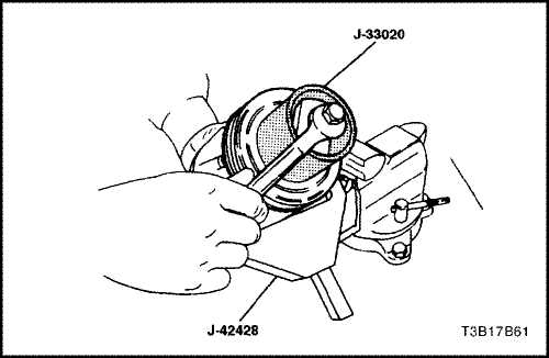
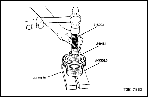
- Install the pulley puller J-33020 into the inner circle of slots in the pulley rotor. Turn the pulley puller J-33020 clockwise in the slots to engage the puller tangs with the segments between the slots in the rotor.
- Hold the pulley puller J-33020 in place and tighten the puller bolt against the compressor shaft to remove the pulley rotor and the bearing assembly.
Notice : The rotor hub must be properly supported to prevent damage to the pulley rotor during bearing removal.
- Remove the puller bolt from the pulley puller J-33020. With the puller tangs still engaged in the rotor slots, invert the assembly onto a solid flat surface or blocks.
Notice : It is not necessary to remove the staking in front of the bearing to remove the bearing. It will be necessary to file away the old stake metal for proper clearance for the new bearing to be installed into the rotor bore or the bearing may be damaged.
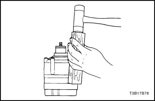
- Drive the bearing out of the rotor hub with the bearing remover J-9398-A and the driver handle J-8092.
Assembly Procedure
Notice : Do not support the rotor by resting the pulley rim on a flat surface during the bearing installation or the rotor face could be damaged.
- Invert the pulley rotor and place it on a support block to fully support the rotor hub during bearing installation.
- Align the new bearing squarely in the pulley bore. Use the bearing installer J-9481 and the driver handle J-8092, drive the bearing fully into the pulley bore.
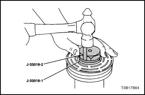
- Place the bearing staking guide J-33019-1 and the bearing staking pin J-33019-2 in the rotor hub core. Shift the rotor and bearing assembly on the block to give full support to the hub under the staking pin location. A heavy-duty rubber band may be used to hold the staking tool pin in the guide. The pin should be properly positioned in the guide after each impact on the pin.
Caution : When striking the pin with a hammer, take care to avoid personal injury.
Notice : Make sure the metal stake does not contact the outer race of the bearing. Otherwise the outer race may become distorted.
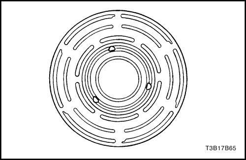
- Strike the pin with a hammer until a metal stake, similar to the original, is formed down to, but not touching, the bearing. The metal stake should not contact the outer race of the bearing to avoid the possibility of distorting the outer race. Stake in three places 120 degrees apart.
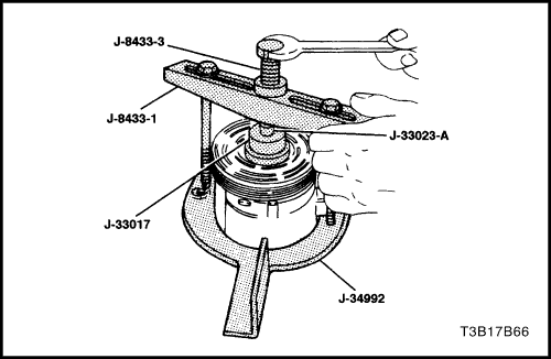
- With the compressor mounted to the holding fixture J-34992, position the rotor and the bearing assembly on the compressor housing.
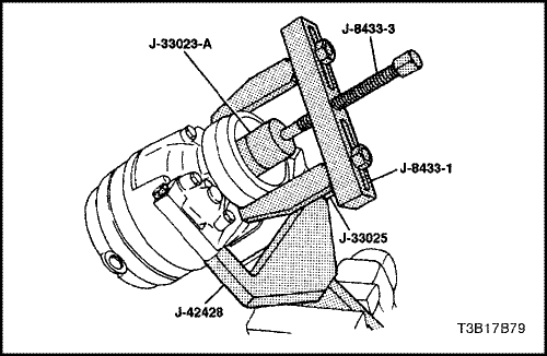
- Position the pulley rotor and bearing assembly installer J-33017 and the puller pilot J-33023-A directly over the inner race of the bearing.
- Position the puller crossbar J-8433-1 center forcing bolt on the puller pilot J-33023-A and assemble the two through-bolts and the washers through the puller crossbar J-8433-1 slots. Thread them into the holding fixture J-34992. The thread of the through-bolts should engage the full thickness of the fixture.
- Tighten the center forcing screw J-8433-3 in the puller crossbar J-8433-1 to force the pulley rotor and the bearing assembly onto the compressor housing.
- Install the rotor and the bearing assembly retainer ring using the snap ring pliers J-6083.
- Reinstall the clutch drive plate and the hub assembly. Refer to "Clutch Plate and Hub Assembly" in this section.
- Install the compressor. Refer to "Compressor" in this section.
- Connect the negative battery cable.
- Evacuate and recharge the A/C system. Refer to "Discharging, Adding Oil, Evacuating, and Charging Procedures for A/C System" in this section.
Clutch Coil
Tools Required
J-8433-1 Puller Crossbar
J-8433-3 Forcing Screw
J-33023-A Puller Pilot
J-33024 Clutch Coil Installer Adapter
J-33025 Clutch Coil Puller Legs
J-34992 Compressor Holding Fixture
Disassembly Procedure
- Disconnect the negative battery cable.
- Recover the refrigerant. Refer to "Discharging, Adding Oil, Evacuating, and Charging Procedures for A/C System" in this section.
- Remove the compressor. Refer to "Compressor" in this section.
- Remove the clutch plate and hub assembly. Refer to "Clutch Plate and Hub Assembly" in this section.
- Remove the clutch rotor and bearing. Refer to "Clutch Rotor and Bearing" in this section.
- Mark the clutch coil terminal location on the compressor housing.
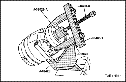
- Install the puller pilot J-33023-A on the compressor housing. Also install the puller crossbar J-8433-1 with the clutch coil puller legs J-33025.
- Tighten the forcing screw J-8433-3 against the puller pilot J-33023-A to remove the clutch coil.
Assembly Procedure
- Place the clutch coil assembly on the compressor housing with the terminals positioned at the "marked" location.
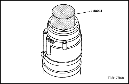
- Place the clutch coil installer adapter J-33024 over the internal opening of the clutch coil housing and align the clutch coil installer adapter J-33024 with the compressor housing.
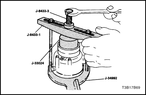
- Center the puller crossbar J-8433-1 in the countersunk center hole of the clutch coil installer adapter J-33024. Install the compressor holding fixture J-34992 through-bolts and the washers through the crossbar slots. Thread them into the holding fixture to the full thickness of the holding fixture.
Important : Be sure the clutch coil and the installer stay "in-line" during installation.
- Turn the forcing screw J-8433-3, or use a suitable vise, to force the clutch coil onto the compressor housing.
- When the clutch coil is fully seated on the compressor housing, use a 3 mm (1/8 inch) diameter drift punch and stake the housing at three places, 120 degrees apart, to ensure that the clutch coil will remain in position. Stake point size should be only one-half the area of the punch tip and approximately 0.28 to 0.35 mm (0.010 to 0.015 inch) deep.
- Install the clutch rotor and bearing assembly. Refer to "Clutch Rotor and Bearing" in this section.
- Install the clutch plate and hub assembly. Refer to "Clutch Plate and Hub Assembly" in this section.
- Install the compressor. Refer to "Compressor" in this section.
- Connect the negative battery cable.
- Evacuate and recharge the A/C system. Refer to "Discharging, Adding Oil, Evacuating, and Charging Procedures for A/C System" in this section.
Shaft Seal Replacement
Tools Required
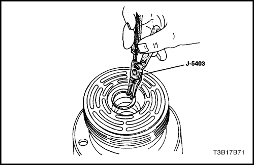
J-5403 Snap Ring Pliers
J-9553-1 O-Ring Remover
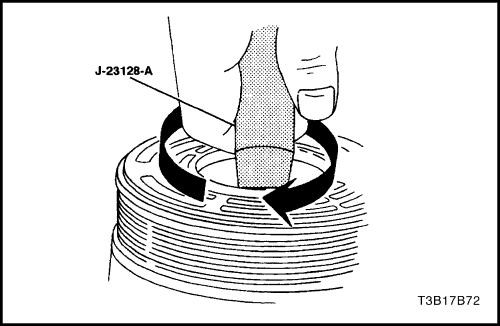
J-23128-A Seal Seat Remover and Installer
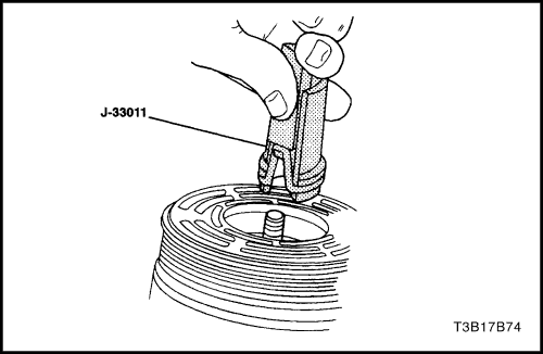
J-33011 O-Ring Installer
J-34614 Shaft Seal Protector
Important : A shaft seal should not be replaced because a small amount of oil is found on the adjacent surface. The seal is designed to leak some oil for lubrication purposes. A shaft seal should be changed only when a large amount of sprayed oil is found and then only after actual refrigerant leakage is found by using an approved leak detection procedure. Refer to "Leak Testing the Refrigerant System" in this section.
Should a compressor shaft seal ever have to be replaced, the receiver-dryer in this system must also be removed from the vehicle. The oil in the receiver-dryer must then be drained, measured and replaced. Refer to "Adding Oil to the Air Conditioning Refrigerant System" in this section.
Disassembly Procedure
- Disconnect the negative battery cable.
- Recover the refrigerant. Refer to "Discharging, Adding Oil, Evacuating, and Charging Procedures for A/C System"
in this section.
- Loosen and reposition the compressor in the mounting brackets.
- Remove the clutch drive plate and hub assembly from the compressor. Refer to "Clutch Plate and Hub Assembly" in this section.
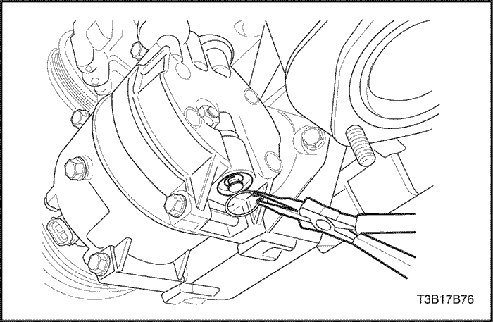
- Use the snap ring pliers J-5403 to remove the shaft seal retaining ring.
Notice : Any dirt or foreign material that enters the compressor may cause damage.
- Thoroughly clean the inside of the compressor housing area surrounding the shaft, the exposed portion of the seal, the shaft itself, and the O-ring groove.
- Fully engage the knurled tangs of the seal seat remover/installer J-23128-A into the recessed portion of the seal by turning the handle clockwise. Remove and discard the seal from the compressor with a rotating-pulling motion. The handle should be hand-tightened securely. Do not use a wrench or pliers to tighten the handle.
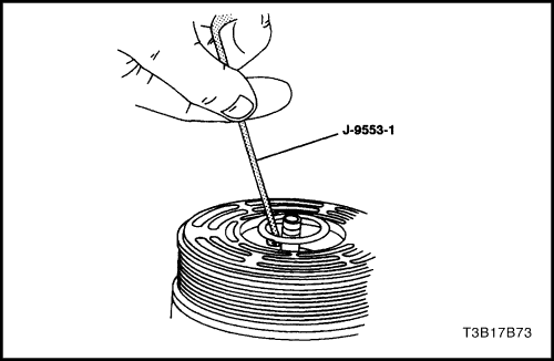
- Remove and discard the O-ring from the compressor neck using the O-ring remover J-9553-1.
- Thoroughly clean the seal O-ring groove in the compressor housing.
- Inspect the shaft and the inside of the compressor housing neck for dirt or foreign material. These parts must be perfectly clean before installing any new parts.
Assembly Procedure
Important : Seals must not be reused. Always use a new specification service seal kit. Be sure that the seal to be installed is not scratched or damaged in any way. The seal must be free of lint and dirt that may damage the seal surface or prevent proper sealing.
- Dip the new seal O-ring in clean polyalkalene glycol (PAG) refrigerant oil and assemble the O-ring onto the O-ring installer J-33011.
- Insert the O-ring installer J-33011 into the compressor neck until the installer "bottoms." Lower the moveable slide of the O-ring installer J-33011 to release the O-ring into the seal O-ring lower groove. (The top groove of the compressor neck is for the shaft seal retainer ring.) Rotate the installer to seat the O-ring and then remove the installer.
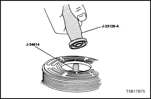
- Attach the shaft lip seal to the seal seat remover/installer J-23128-A. Dip the seal in clean PAG oil.
- Install the shaft seal protector J-34614 in the seal. Place it over the shaft and push the seal into place with a rotary motion.
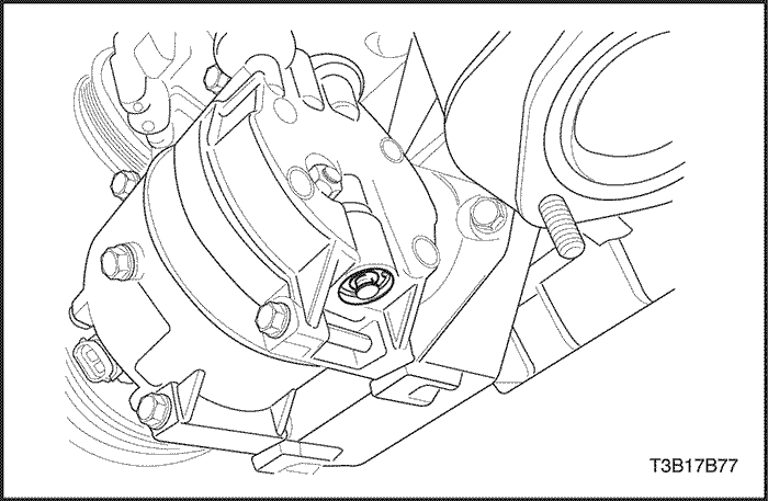
- Use the snap ring pliers J-5403 to install the shaft seal retaining ring with its flat side against the seal.
- Remove any excess oil around the shaft and the inside of the compressor housing neck.
- Install the clutch plate and hub assembly. Refer to "Clutch Plate and Hub Assembly" in this section.
- Reposition the compressor in its mounting.
- Adjust the tension on the drive belt.
- Connect the negative battery cable.
- Evacuate and recharge the A/C system. Refer to "Discharging, Adding Oil, Evacuating, and Charging Procedures for A/C System" in this section.
- Perform a leak test of the system. Refer to "Leak Testing the Refrigerant System" in this section.
Control Valve Assembly
Tools Required
Disassembly Procedure
- Recover the refrigerant. Refer to "Discharging, Adding Oil, Evacuating, and Charging Procedures for A/C System" in this section.
- Remove the control valve retaining ring using the snap ring pliers J-5403.
- Remove the control valve assembly.
Assembly Procedure
- Coat all the O-rings with clean polyalkalene glycol (PAG) oil.
- Push the control valve in place using thumb pressure.
- Use the snap ring pliers J-5403 to install the valve retaining ring. The high point of the curved sides must be against the valve housing. Be sure the retaining ring is properly seated in the ring groove.
- Evacuate and recharge the A/C system. Refer to "Discharging, Adding Oil, Evacuating, and Charging Procedures for A/C System" in this section.
Rear Head, Gasket, Valve Plate, Reed Plate, and O-ring
Tools Required
J-34993 Cylinder Alignment Rods
Disassembly Procedure
- Recover the refrigerant. Refer to "Discharging, Adding Oil, Evacuating, and Charging Procedures for A/C System" in this section.
- Discharge the A/C system. Refer to "Discharging, Adding Oil, Evacuating, and Charging Procedures for A/C System"
in this section.
- Remove the compressor. Refer to "Compressor" in this section.
- Drain the oil from compressor into a suitable container. Measure and record the amount of oil drained from the compressor. Discard the used oil.
- Remove the clutch plate and hub assembly. Refer to "Clutch Plate and Hub Assembly" in this section.
- Remove the clutch rotor and bearing. Refer to "Clutch Rotor and Bearing" in this section.
- Remove the clutch coil. Refer to "Clutch Coil" in this section.
- Remove the compressor through-bolts. Remove and discard the gaskets.
- Using a wooden block and a plastic-headed hammer, tap around the edge of the rear head to disengage the head from the compressor cylinder. Separate the rear head, the head gasket, the rear valve plate, the suction reed plate, and the cylinder to rear head O-ring. Discard the head gasket and the O-ring.
Assembly Procedure
- Place the rear head on a clean, flat surface. Position the head with the control valve at the 6 o'clock position.
- Install the cylinder alignment rods J-34993 in the mounting holes at the 11 o'clock and the 5 o'clock positions.
- Install the head gasket over the cylinder alignment rods J-34993 with the elongated hole at the upper left pin (the 11 o'clock position).
- Install the rear head valve plate over the cylinder alignment rods J-34993 with the elongated hole at the upper left alignment rod. Lower the rear head valve plate into place.
- Install the suction reed plate over the cylinder alignment rods J-34993. Remove the alignment rod at the 5 o'clock position.
- Lubricate the cylinder to the new rear head O-ring with clean polyalkaline glycol (PAG) refrigerant oil.
- Install the O-ring in the cylinder O-ring groove. The O-ring seal surface of the head may be lubricated to ease assembly.
- With the O-ring in place on the rear of the cylinder assembly, locate the relief boss for the alignment rod at the 6 o'clock position, directly above the hole in the side of the rear head. Carefully lower the cylinder and the front head assembly over the cylinder alignment rods to the rear head.
- Press the cylinder and the compressor housing assembly down onto the rear head using both hands.
- Add the new through-bolt gasket to the throughbolts and install it into the compressor assembly. Four of the through-bolts must thread into the rear head before removing the alignment rods.
Tighten
Alternately tighten the compressor front head-to-rear head through-bolts in progressive torque sequence to 10 N•m (89 lb-in).
- Add new PAG refrigerant oil as determined in Step 1.
- Place the shaft nut on the shaft and rotate the compressor shaft several times.
- Perform a leak test on the compressor. Refer to "Leak Testing (External)" in this section.
- Install the clutch coil. Refer to "Clutch Coil" in this section.
- Install the clutch rotor and bearing. Refer to "Clutch Rotor and Bearing" in this section.
- Install the clutch plate and hub assembly. Refer to "Clutch Plate and Hub Assembly" in this section.
- Install the compressor. Refer to "Compressor" in this section.
- Evacuate and recharge the A/C system. Refer to "Discharging, Adding Oil, Evacuating, and Charging Procedures for A/C System" in this section.
Cylinder-to-Front Head O-ring
Tools Required
J-34993 Cylinder Alignment Rods
J-35372 Support Block
Disassembly Procedure
- Recover the refrigerant. Refer to "Discharging, Adding Oil, Evacuating, and Charging Procedures for A/C System"
in this section.
- Remove the compressor. Refer to "Compressor"
in this section.
- Drain the oil from compressor into a suitable container. Measure and record the amount of oil drained from the compressor. Discard all used oil.
- Remove the clutch plate and hub assembly. Refer to "Clutch Plate and Hub Assembly"
in this section.
- Remove the clutch rotor and bearing. Refer to "Clutch Rotor and Bearing"
in this section.
- Remove the clutch coil. Refer to "Clutch Coil"
in this section.
- Remove and discard the shaft seal parts. Refer to "Shaft Seal Replacement" in this section.
- Remove the compressor through-bolts. Remove and discard the gaskets.
- Using a wooden block and a plastic-headed hammer, tap the compressor housing at the mounting locations to disengage the housing from the compressor cylinder.
Important : Note the assembly sequence of the thrust washer and bearing for ease of assembly.
- Remove the thrust washer and the bearing.
- Remove and discard the compressor housing-to-cylinder O-ring.
Assembly Procedure
- Rest the rear head on the support block J-35372. Locate the control valve in the 6 o'clock position.
- Install cylinder alignment rod J-34993 through the 11 o'clock and the 5 o'clock bolt holes.
- Lubricate the new cylinder-to-compressor housing O-ring with clean polyalkalene glycol (PAG) oil.
- Install the new O-ring in the cylinder O-ring groove.
- Install the thrust washer and bearing in the same order as they were removed.
- Align the cylinder alignment rod recess in the compressor housing with the cylinder alignment rod. Press down on the compressor housing with both hands to force it over the O-ring on the cylinder assembly.
- Add a new through-bolt gasket to the through-bolts and install them into the compressor assembly. Four through-bolts must thread into the rear head before removing the cylinder alignment rods.
Tighten
Alternately tighten the compressor front head-to-rear head through-bolts in progressive torque sequence to 10 N•m (89 lb-in).
- Install a new shaft seal. Refer to "Shaft Seal Replacement"
in this section.
- Add new PAG oil equal to the amount drained in Step 3.
- Install the clutch coil. Refer to "Clutch Coil"
in this section.
- Install the clutch rotor and bearing. Refer to "Clutch Rotor and Bearing"
in this section.
- Install the clutch plate and hub assembly. Refer to "Clutch Plate and Hub Assembly"
in this section.
- Perform a leak test on the compressor. Refer to "Leak Testing (External)"
in this section.
- Install the compressor. Refer to "Compressor"
in this
section.
- Evacuate and recharge the A/C system. Refer to "Discharging, Adding Oil, Evacuating, and Charging Procedures for A/C System"
in this section.
Leak Testing - External -
Tools Required
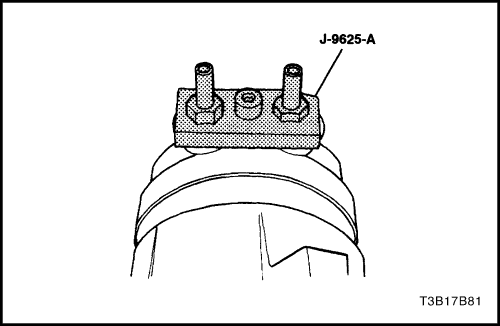
J-9625-A Pressure Test Set
- Install the pressure test set connector J-9625-A to the suction/discharge ports on the compressor.
- Attach the center hose of the manifold gauge set on the charging station to a refrigerant drum standing in an upright position. Open the valve on the drum.
- Connect the charging station high and low-pressure lines to the corresponding fittings on the pressure test set connectors J-9625-A (or hoses equipped with valve depressors). The suction port (low-side) of the compressor has a large internal opening. The discharge port (high-side) has a smaller internal opening into the compressor.
- Open the low pressure control, the high-pressure control and the refrigerant control on the charging station to allow the refrigerant vapor to flow into the compressor.
- Using a leak detector, check for leaks at the high-pressure relief valve seal, the housing seal, the rear head seal, the center cylinder seal, the through-bolt gaskets, and the compressor shaft seal. After checking for leaks, shut off the low pressure control, the high pressure control and the refrigerant control lines on the charging station.
- If an external leak is present, perform the necessary corrective measures and recheck for leaks to verify that the leak has been corrected.
- Loosen the manifold gauge hose connections to the gauge adapters connected to the low and high sides. Allow the vapor pressure to release from the compressor. If valve depressor-type hoses are used, loosen the hose connections at the gauge manifold to release vapor pressure from the compressor.
- Disconnect both gauge hoses. Remove the pressure test set connector J-9625-A.
SP10 AIR CONDITIONING COMPRESSOR OVERHAUL
Clutch & Drive Assembly
Tools Required
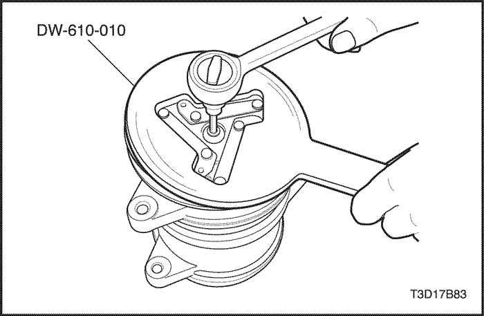
DW-610-010 Clutch Hub Holding Tool
Disassembly Procedure
- Remove the compressor. Refer to "Compressor" in this section.
- Use the clutch hub holding tool DW-610-010 to keep the clutch drive assembly from turning.
- Remove the shaft bolt.
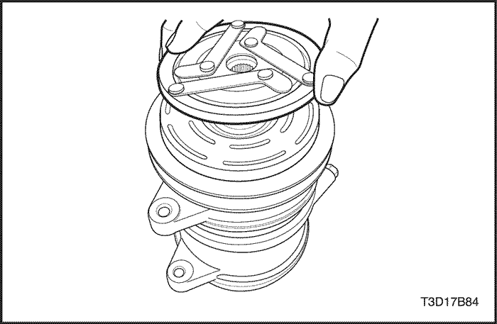
- Pull the clutch drive assembly up by hand.
Assembly Procedure
- Place the clutch drive assembly to match the shaft serration with drive hub serration.
- Gently insert the clutch drive assembly.
- Check the air gap with the feeler gage roughly by pressing the clutch drive assembly before fastening the shaft bolt.
Notice : If air gap is correct, proceed next step, if not, change the shim to meet the air gap (Standard air gap is 0.3~0.7 mm (0.012~0.028 in)).
- Place the washer before fastening the shaft bolt.
Tighten
Tighten the shaft bolt to 12~15 N•m (106~133 lb-in).
- Re-check the air gap with feeler gage.
Pulley & Bearing Assembly
Tools Required
J-9553-1 O-Ring Remover
(for shim removal purpose)
Disassembly Procedure
- Remove the clutch & drive assembly. Refer to "Clutch & Drive Assembly" in this section.
- Remove the shims using J-9553-1 O-Ring remover.
- Remove the pulley ring retainer using the snap ring pliers.
- Pull the pulley groove with both hands until the pulley & bearing assembly is free.
Assembly Procedure
- Locate the rotor pulley on the front head housing squarely and precisely.
- Insert the pulley & bearing assembly by gradually increasing the force on the pulley surface.
Caution : Never use hammer to prevent the damage on the pulley bearing.
Caution : Listen for a distinct change of sound during installation process to make sure that it is seated properly.
- Check for proper installation of pulley by spinning it.
- Install the retainer ring using snap ring pliers.
Caution : Care must be taken to avoid damage to the bearing seal when assembling.
Caution : Sharp edge of the retainer should be placed on upper side.
Caution : Squeezing after installation is required to make sure that it was well installed.
- Place the shim(s) on the shaft shoulder. Determine how many shims and what type of shim to be used to make an air gap between 0.3~0.7 mm (0.012~0.028 in).
- Install the clutch & drive assembly. Refer to "Clutch & Drive Assembly"
in this section.
Coil & Housing Assembly
Disassembly Procedure
- Remove the clutch & drive assembly. Refer to "Clutch & Drive Assembly"
in this section.
- Remove the pulley & bearing assembly. Refer to "Pulley & Bearing Assembly"
in this section.
- Remove the coil retainer using the snap ring pliers.
- Remove the coil & housing assembly.
Caution : Care must be taken to avoid damage to the lead wire clamp for re-use.
Assembly Procedure
- Gently install the coil & housing assembly. The lead wire clamp must be inserted tightly onto the front head slot.
Caution : Coil flange protrusion must match front head hole to prevent coil movement and correctly locate the lead wire.
Caution : The lead wire must be tightened by pulling toward the compressor body to prevent it from touching the pulley.
- Install the retainer ring using the snap ring pliers.
Caution : Make sure that the sharp edge side of the coil retainer should be placed on upper side. (It may occur durability problem if retainer is not assembled correctly.)
Caution : After assembling, squeezing the retainer is required to make sure that the retainer was well installed.
- Install the pulley & bearing assembly. Refer to "Pulley & Bearing Assembly"
in this section.
- Install the clutch & drive assembly. Refer to "Clutch & Drive Assembly"
in this section.
Clutch Function Test
- Perform the clutch engagement and disengagement more than 2 cycles to check the proper clutch operation.
- If the clutch does not engage within 1 second with 9 volts, check the resistance of coil. (Coil resistance Specification is 4.4±0.2 Ohms at 20°C (68°F))
| © Copyright Chevrolet Europe. All rights reserved |


