Diagnostic Trouble Code - DTC - B1367
Passenger Beltpretensioner Resistance Too Low
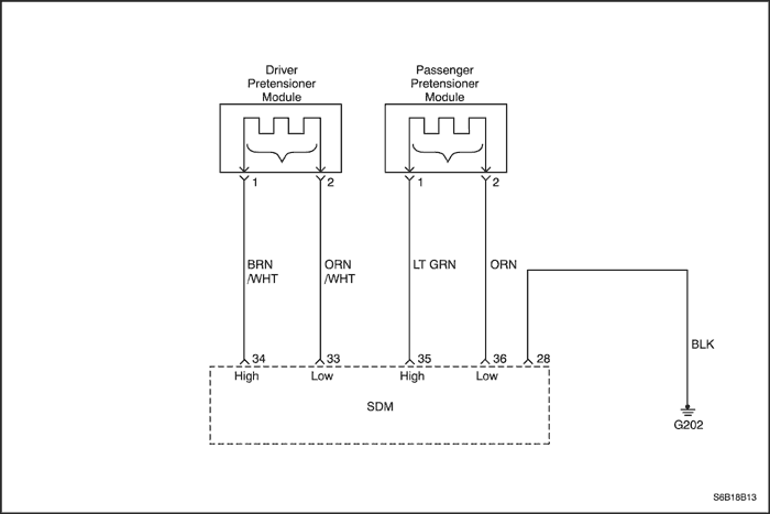
Circuit Description
When the ignition switch is turned to ON, the sensing and diagnostic module(SDM) will perform turn-on test to diagnose critical malfunctions within SDM itself.
Upon passing these test ignition and deployment loop voltages are measured to ensure that they are within their normal voltage ranges. The SDM monitors the voltages at the driver low and the passenger low to detect shorts to ground or voltage in the deploy loops.
The SDM checks the wiring connection to the passenger belt pretensioner by letting the infinitesimal current flow through the internal circuit and verify the resistance.
DTC B1367 Will Set When
- The resistance of passenger belt pretensioner deploy loop is over 3.54 ohms.
DTC B1367 - Passenger Beltpretensioner Resistance Too Low
Caution : The sensing and diagnostic module(SDM) can maintain sufficient voltage to deploy the airbags and pretensioners for 1 minute after the ignition is OFF and the fuse has been removed. If the airbags and pretensioners are not disconnected, do not begin service until one minute has passed after disconnecting power to SDM. Otherwise, injury could result.
Caution : During service procedure, be very careful when handling the SDM. Never strike or jar the SDM. Never power the supplemental inflatable restraints(SIR) when the SDM is not rigidly attached to the vehicle. All SDM mounting bolts must be carefully tightened , and the arrow on the SDM must be point toward the front of the vehicle to ensure proper operation of the SIR. The SDM could be activated if it is powered when it is not rigidly attached to the vehicle, resulting in unexpected deployment and possible injury.
| Step |
Action |
Value(s) |
Yes |
No |
| 1 |
- Confirm the ignition switch "OFF".
- Wait for a minute to discharge the SDM charger.
|
-
|
Go to Step 2
|
-
|
| 2 |
Visually inspect the connector and the wiring of passenger belt pretensioner.
Is the connector disconnected?
|
-
|
Connect the connector and go to Step 1
|
Go to Step 3
|
| 3 |
- Confirm the ignition switch "OFF".
- Disconnect the connector of the passenger belt pretensioner.
- Disconnect the connector of SDM wiring.
- Check the resistance between the terminal 35, 36 of SDM and the terminal 1, 2 of passenger belt pretensioner.
Is the resistance about 0(zero)?
|
≈ 0 Ω
|
Go to Step 4
|
Replace the airbag wiring.
|
| 4 |
- Replace the SDM.
- Confirm the ignition switch "ON".
- Erase the DTC using scan tool.
- Perform the SIR Diagnostic System Check.
Is the DTC removed?
|
-
|
The System is OK.
|
Replace the passenger belt pretensioner.
|
Diagnostic Trouble Code - DTC - B1368
Passenger Beltpretensioner Resistance Too Low
Circuit Description
When the ignition switch is turned to ON, the sensing and diagnostic module(SDM) will perform turn-on test to diagnose critical malfunctions within SDM itself.
Upon passing these test ignition and deployment loop voltages are measured to ensure that they are within their normal voltage ranges. The SDM monitors the voltages at the driver low and the passenger low to detect shorts to ground or voltage in the deploy loops.
The SDM checks the wiring connection to the passenger belt pretensioner by letting the infinitesimal current flow through the internal circuit and verify the resistance.
DTC B1368 Will Set When
- The resistance of passenger belt pretensioner deploy loop is lower than 1.77 ohms.
- The shorting bar is damaged and then the SDM must be replaced .
DTC B1368 - Passenger Beltpretensioner Resistance Too Low
Caution : The sensing and diagnostic module(SDM) can maintain sufficient voltage to deploy the airbags and pretensioners for 1 minute after the ignition is OFF and the fuse has been removed. If the airbags and pretensioners are not disconnected, do not begin service until one minute has passed after disconnecting power to SDM. Otherwise, injury could result.
Caution : During service procedure, be very careful when handling the SDM. Never strike or jar the SDM. Never power the supplemental inflatable restraints(SIR) when the SDM is not rigidly attached to the vehicle. All SDM mounting bolts must be carefully tightened , and the arrow on the SDM must be point toward the front of the vehicle to ensure proper operation of the SIR. The SDM could be activated if it is powered when it is not rigidly attached to the vehicle, resulting in unexpected deployment and possible injury.
| Step |
Action |
Value(s) |
Yes |
No |
| 1 |
- Confirm the ignition switch "OFF".
- Wait for a minute to discharge the SDM charger.
|
-
|
Go to Step 1
|
-
|
| 2 |
Visually inspect the connector and the wiring of passenger belt pretensioner.
Is the wiring damaged?
|
-
|
Replace the airbag wiring.
|
Go to Step 3
|
| 3 |
- Confirm the ignition switch "OFF".
- Disconnect the connector of the passenger belt pretensioner.
- Disconnect the connector of SDM wiring.
- Check the resistance between the terminal 1 and 2 of passenger belt pretensioner.
Is the resistance ∞?
|
∞
|
Go to Step 4
|
Replace the airbag wiring.
|
| 4 |
- Replace the SDM.
- Confirm the ignition switch "ON".
- Erase the DTC using scan tool.
- Perform the SIR Diagnostic System Check.
Is the DTC removed?
|
-
|
The System is OK.
|
Replace the passenger belt pretensioner.
|
Diagnostic Trouble Code - DTC - B1369
Passenger Beltpretensioner Short to Ground
Circuit Description
When the ignition switch is turned to ON, the sensing and diagnostic module(SDM) will perform turn-on test to diagnose critical malfunctions within SDM itself.
Upon passing these test ignition and deployment loop voltages are measured to ensure that they are within their normal voltage ranges. The SDM monitors the voltages at the driver low and the passenger low to detect shorts to ground or voltage in the deploy loops.
The SDM checks the wiring connection to the passenger belt pretensioner by letting the infinitesimal current flow through the internal circuit and verify the resistance.
DTC B1369 Will Set When
- The belt pretensioner wiring of passenger's high is shorted to ground.
- The belt pretensioner wiring of passenger's low is shorted to ground.
DTC B1369 – Passenger Beltpretensioner Short to Ground
Caution : The sensing and diagnostic module(SDM) can maintain sufficient voltage to deploy the airbags and pretensioners for 1 minute after the ignition is OFF and the fuse has been removed. If the airbags and pretensioners are not disconnected, do not begin service until one minute has passed after disconnecting power to SDM. Otherwise, injury could result.
Caution : During service procedure, be very careful when handling the SDM. Never strike or jar the SDM. Never power the supplemental inflatable restraints(SIR) when the SDM is not rigidly attached to the vehicle. All SDM mounting bolts must be carefully tightened , and the arrow on the SDM must be point toward the front of the vehicle to ensure proper operation of the SIR. The SDM could be activated if it is powered when it is not rigidly attached to the vehicle, resulting in unexpected deployment and possible injury .
| Step |
Action |
Value(s) |
Yes |
No |
| 1 |
- Confirm the ignition switch "OFF".
- Wait for a minute to discharge the SDM charger.
|
-
|
Go to Step 2
|
-
|
| 2 |
Visually inspect the connector and the wiring of passenger belt pretensioner.
Is the wiring damaged?
|
-
|
Replace the airbag wiring.
|
Go to Step 3
|
| 3 |
- Confirm the ignition switch "OFF".
- Disconnect the connector of the passenger belt pretensioner.
- Disconnect the connector of SDM wiring.
- Check the resistance between the high, low wiring of passenger belt pretensioner and the ground.
Is the resistance higher than 10KΩ?
|
10KΩ
|
Go to Step 4
|
Replace the airbag wiring.
|
| 4 |
- Replace the SDM.
- Confirm the ignition switch "ON".
- Erase the DTC using scan tool.
- Perform the SIR Diagnostic System Check.
Is the DTC removed?
|
-
|
The System is OK.
|
Replace the passenger belt pretensioner.
|
Diagnostic Trouble Code - DTC - B1370
Passenger Beltpretensioner Short to Battery
Circuit Description
When the ignition switch is turned to ON, the sensing and diagnostic module(SDM) will perform turn-on test to diagnose critical malfunctions within SDM itself.
Upon passing these test ignition and deployment loop voltages are measured to ensure that they are within their normal voltage ranges. The SDM monitors the voltages at the driver low and the passenger low to detect shorts to ground or voltage in the deploy loops.
The SDM checks the wiring connection to the passenger belt pretensioner by letting the infinitesimal current flow through the internal circuit and verify the resistance.
DTC B1370 Will Set When
- The belt pretensioner wiring of passenger's high is shorted to battery wiring.
- The belt pretensioner wiring of passenger's low is shorted to battery wiring.
DTC B1370 - Passenger Beltpretensioner Short to Battery
Caution : The sensing and diagnostic module(SDM) can maintain sufficient voltage to deploy the airbags and pretensioners for 1 minute after the ignition is OFF and the fuse has been removed. If the airbags and pretensioners are not disconnected, do not begin service until one minute has passed after disconnecting power to SDM. Otherwise, injury could result.
Caution : During service procedure, be very careful when handling the SDM. Never strike or jar the SDM. Never power the supplemental inflatable restraints(SIR) when the SDM is not rigidly attached to the vehicle. All SDM mounting bolts must be carefully tightened , and the arrow on the SDM must be point toward the front of the vehicle to ensure proper operation of the SIR. The SDM could be activated if it is powered when it is not rigidly attached to the vehicle, resulting in unexpected deployment and possible injury.
| Step |
Action |
Value(s) |
Yes |
No |
| 1 |
- Confirm the ignition switch "OFF".
- Wait for a minute to discharge the SDM charger.
|
-
|
Go to Step 2
|
-
|
| 2 |
Visually inspect the connector and the wiring of passenger belt pretensioner.
Is the wiring damaged?
|
-
|
Replace the airbag wiring.
|
Go to Step 3
|
| 3 |
- Confirm the ignition switch "OFF".
- Disconnect the connector of the passenger belt pretensioner.
- Disconnect the connector of SDM wiring.
- Check the resistance between the high, low wiring of passenger belt pretensioner and the battery.
Is the resistance higher than 10KΩ?
|
10KΩ
|
Go to Step 4
|
Replace the airbag wiring.
|
| 4 |
- Replace the SDM.
- Confirm the ignition switch "ON".
- Erase the DTC using scan tool.
- Perform the SIR Diagnostic System Check.
Is the DTC removed?
|
-
|
The System is OK.
|
Replace the passenger belt pretensioner.
|
Diagnostic Trouble Code - DTC - B1378
Driver Side Airbag Resistance Too High
Circuit Description
When the ignition switch is turned to ON, the sensing and diagnostic module(SDM) will perform turn-on test to diagnose critical malfunctions within SDM itself.
Upon passing these test ignition and deployment loop voltages are measured to ensure that they are within their normal voltage ranges. The SDM monitors the voltages at the driver low and the passenger low to detect shorts to ground or voltage in the deploy loops.
The SDM checks the wiring connection to the driver side airbag module by letting the infinitesimal current flow through the internal circuit and verify the resistance.
DTC B1378 Will Set When
- The resistance of driver side airbag deployment loop is higher than 3.54 ohms.
DTC B1378 – Driver Side Airbag Resistance Too High
Caution : The sensing and diagnostic module(SDM) can maintain sufficient voltage to deploy the irabags and pretensioners for 1 minute after the ignition is OFF and the fuse has been removed. If the airbags and pretensioners are not disconnected, do not begin service until one minute has passed after disconnecting power to SDM. Otherwise, injury could result.
Caution : During service procedure, be very careful when handling the SDM. Never strike or jar the SDM. Never power the supplemental inflatable restraints(SIR) when the SDM is not rigidly attached to the vehicle. All SDM mounting bolts must be carefully tightened , and the arrow on the SDM must be point toward the front of the vehicle to ensure proper operation of the SIR. The SDM could be activated if it is powered when it is not rigidly attached to the vehicle, resulting in unexpected deployment and possible injury.
| Step |
Action |
Value(s) |
Yes |
No |
| 1 |
- Confirm the ignition switch "OFF".
Wait for a minute to discharge the SDM charger.
|
-
|
Go to Step 2
|
-
|
| 2 |
Visually inspect the connector and the wiring of driver side airbag.
Is the connector disconnected?
|
-
|
Connect the connector and go to Step 1
|
Go to Step 3
|
| 3 |
- Confirm the ignition switch "OFF".
- Disconnect the connector of the driver side airbag module.
- Disconnect the connector of SDM wiring.
- Check the resistance between the terminal 38, 37 of SDM and the terminal 1, 2 of driver side airbag module.
Is the resistance about 0(zero) ?
|
≈ 0 Ω
|
Go to Step 4
|
Replace the airbag wiring.
|
| 4 |
- Replace the SDM.
- Confirm the ignition switch "ON".
- Erase the DTC using scan tool.
- Perform the SIR Diagnostic System Check.
Is the DTC removed?
|
-
|
The System is OK
|
Replace the driver side airbag module.
|
Diagnostic Trouble Code - DTC - B1379
Driver Side Airbag Resistance Too Low
Circuit Description
When the ignition switch is turned to ON, the sensing and diagnostic module(SDM) will perform turn-on test to diagnose critical malfunctions within SDM itself.
Upon passing these test ignition and deployment loop voltages are measured to ensure that they are within their normal voltage ranges. The SDM monitors the voltages at the driver low and the passenger low to detect shorts to ground or voltage in the deploy loops.
The SDM checks the wiring connection to the driver side airbag module by letting the infinitesimal current flow through the internal circuit and verify the resistance.
DTC B1379 Will Set When
- The resistance of driver airbag deployment loop is lower than 1.77 ohms.
- The shorting bar is damaged and then the SDM must be replaced .
DTC B1379 - Driver Side Airbag Resistance Too Low
Caution : The sensing and diagnostic module(SDM) can maintain sufficient voltage to deploy the airbags and pretensioners for 1 minute after the ignition is OFF and the fuse has been removed. If the airbags and pretensioners are not disconnected, do not begin service until one minute has passed after disconnecting power to SDM. Otherwise, injury could result.
Caution : During service procedure, be very careful when handling the SDM. Never strike or jar the SDM. Never power the supplemental inflatable restraints(SIR) when the SDM is not rigidly attached to the vehicle. All SDM mounting bolts must be carefully tightened , and the arrow on the SDM must be point toward the front of the vehicle to ensure proper operation of the SIR. The SDM could be activated if it is powered when it is not rigidly attached to the vehicle, resulting in unexpected deployment and possible injury.
| Step |
Action |
Value(s) |
Yes |
No |
| 1 |
- Confirm the ignition switch "OFF".
- Wait for a minute to discharge the SDM charger.
|
-
|
Go to Step 2
|
-
|
| 2 |
Visually inspect the connector and the wiring of driver side airbag.
Is the airbag wiring damaged?
|
-
|
Replace the airbag wiring.
|
Go to Step 3
|
| 3 |
- Confirm the ignition switch "OFF".
- Disconnect the connector of the driver side airbag module.
- Disconnect the connector of SDM wiring.
- Check the resistance between the terminal 2 and 1 of driver side airbag module.
Is the resistance ∞?
|
∞
|
Go to Step 4
|
Replace the airbag wiring.
|
| 4 |
- Replace the SDM.
- Confirm the ignition switch "ON".
- Erase the DTC using scan tool.
- Perform the SIR Diagnostic System Check.
Is the DTC removed?
|
-
|
The System is OK.
|
Replace the driver side airbag module.
|
Diagnostic Trouble Code - DTC - B1380
Driver Side Airbag Short to Ground
Circuit Description
When the ignition switch is turned to ON, the sensing and diagnostic module(SDM) will perform turn-on test to diagnose critical malfunctions within SDM itself.
Upon passing these test ignition and deployment loop voltages are measured to ensure that they are within their normal voltage ranges. The SDM monitors the voltages at the driver low and the passenger low to detect shorts to ground or voltage in the deploy loops.
The SDM checks the wiring connection to the driver side airbag module by letting the infinitesimal current flow through the internal circuit and verify the resistance.
DTC B1380 Will Set When
- The side airbag wiring of driver’s high is shorted to ground.
- The side airbag wiring of driver’s low is shorted to ground.
DTC B1380 – Driver Side Airbag Short to Ground
Caution : The sensing and diagnostic module(SDM) can maintain sufficient voltage to deploy the airbags and pretensioners for 1 minute after the ignition is OFF and the fuse has been removed. If the airbags and pretensioners are not disconnected, do not begin service until one minute has passed after disconnecting power to SDM. Otherwise, injury could result.
Caution : During service procedure, be very careful when handling the SDM. Never strike or jar the SDM. Never power the supplemental inflatable restraints(SIR) when the SDM is not rigidly attached to the vehicle. All SDM mounting bolts must be carefully tightened , and the arrow on the SDM must be point toward the front of the vehicle to ensure proper operation of the SIR. The SDM could be activated if it is powered when it is not rigidly attached to the vehicle, resulting in unexpected deployment and possible injury.
| Step |
Action |
Value(s) |
Yes |
No |
| 1 |
- Confirm the ignition switch "OFF".
- Wait for a minute the SDM charger to be discharged.
|
-
|
Go to Step 2
|
-
|
| 2 |
Visually inspect the connector and the wiring of driver side airbag.
Is the wiring damaged?
|
-
|
Replace the airbag wiring.
|
Go to Step 3
|
| 3 |
- Confirm the ignition switch "OFF".
- Disconnect the connector of the driver side airbag module.
- Disconnect the connector of SDM wiring.
- Check the resistance between the high, low terminal of driver side airbag module and the ground.
Is the resistance higher than 10KΩ?
|
10KΩ
|
Go to Step 4
|
Replace the airbag wiring.
|
| 4 |
- Replace the SDM.
- Confirm the ignition switch "ON".
- Erase the DTC using scan tool.
- Perform the SIR Diagnostic System Check.
Is the DTC removed?
|
-
|
The System is OK.
|
Replace the driver side airbag module.
|
Diagnostic Trouble Code - DTC - B1381
Driver Side Airbag Short to Battery
Circuit Description
When the ignition switch is turned to ON, the sensing and diagnostic module(SDM) will perform turn-on test to diagnose critical malfunctions within SDM itself.
Upon passing these test ignition and deployment loop voltages are measured to ensure that they are within their normal voltage ranges. The SDM monitors the voltages at the driver low and the passenger low to detect shorts to ground or voltage in the deploy loops.
The SDM checks the wiring connection to the driver side airbag module by letting the infinitesimal current flow through the internal circuit and verify the resistance.
DTC B1381 Will Set When
- The side airbag wiring of driver's high is shorted to battery wiring.
- The side airbag wiring of driver's low is shorted to battery wiring.
DTC B1381 - Driver Side Airbag Short to Battery
Caution : The sensing and diagnostic module(SDM) can maintain sufficient voltage to deploy the airbags and pretensioners for 1 minute after the ignition is OFF and the fuse has been removed. If the airbags and pretensioners are not disconnected, do not begin service until one minute has passed after disconnecting power to SDM. Otherwise, injury could result.
Caution : During service procedure, be very careful when handling the SDM. Never strike or jar the SDM. Never power the supplemental inflatable restraints(SIR) when the SDM is not rigidly attached to the vehicle. All SDM mounting bolts must be carefully tightened , and the arrow on the SDM must be point toward the front of the vehicle to ensure proper operation of the SIR. The SDM could be activated if it is powered when it is not rigidly attached to the vehicle, resulting in unexpected deployment and possible injury.
| Step |
Action |
Value(s) |
Yes |
No |
| 1 |
- Confirm the ignition switch "OFF".
- Wait for a minute the SDM charger to be discharged.
|
-
|
Go to Step 2
|
-
|
| 2 |
Visually inspect the connector and the wiring of driver side airbag.
Is the wiring damaged?
|
-
|
Replace the airbag wiring.
|
Go to Step 3
|
| 3 |
- Confirm the ignition switch "OFF".
- Disconnect the connector of the driver side airbag module.
- Disconnect the connector of SDM wiring.
- Check the resistance between the SDM and the high, low terminal of driver side airbag module and the battery.
Is the resistance higher than 10KΩ?
|
10KΩ
|
Go to Step 4
|
Replace the airbag wiring.
|
| 4 |
- Replace the SDM.
- Confirm the ignition switch "ON".
- Erase the DTC using scan tool.
- Perform the SIR Diagnostic System Check.
Is the DTC removed?
|
-
|
The system is OK.
|
Replace the driver side airbag module.
|
Diagnostic Trouble Code - DTC - B1382
Passenger Side Airbag Resistance Too High
Circuit Description
When the ignition switch is turned to ON, the sensing and diagnostic module(SDM) will perform turn-on test to diagnose critical malfunctions within SDM itself.
Upon passing these test ignition and deployment loop voltages are measured to ensure that they are within their normal voltage ranges. The SDM monitors the voltages at the driver low and the passenger low to
detect shorts to ground or voltage in the deploy loops.
The SDM checks the wiring connection to the passenger side airbag module by letting the infinitesimal current flow through the internal circuit and verify the resistance.
DTC B1382 Will Set When
- The resistance of passenger side airbag deployment loop is over 3.54 ohms.
DTC B1382 - Passenger Side Airbag Resistance Too High
Caution : The sensing and diagnostic module(SDM) can maintain sufficient voltage to deploy the airbags and pretensioners for 1 minute after the ignition is OFF and the fuse has been removed. If the airbags and pretensioners are not disconnected, do not begin service until one minute has passed after disconnecting power to SDM. Otherwise, injury could result.
Caution : During service procedure, be very careful when handling the SDM. Never strike or jar the SDM. Never power the supplemental inflatable restraints(SIR) when the SDM is not rigidly attached to the vehicle. All SDM mounting bolts must be carefully tightened , and the arrow on the SDM must be point toward the front of the vehicle to ensure proper operation of the SIR. The SDM could be activated if it is powered when it is not rigidly attached to the vehicle, resulting in unexpected deployment and possible injury.
| Step |
Action |
Value(s) |
Yes |
No |
| 1 |
- Confirm the ignition switch "OFF".
- Wait for a minute to discharge the SDM charger.
|
-
|
Go to Step 2
|
-
|
| 2 |
Visually inspect the connector and the wiring of passenger side airbag.
Is the connector disconnected?
|
-
|
Connect the connector and go to step 1
|
Go to step 3
|
| 3 |
- Confirm the ignition switch "OFF".
- Disconnect the connector of passenger side airbag module.
- Disconnect the connector of SDM wiring.
- Check the resistance between the terminal 2, 1 of passenger side airbag module and the terminal 39, 40 of SDM.
Is the resistance about 0(zero)?
|
≈ 0 Ω
|
Go to Step 4
|
Replace the airbag wiring.
|
| 4 |
- Replace the SDM.
- Confirm the ignition switch "ON".
- Erase the DTC using scan tool
- Perform the SIR Diagnostic System Check.
Is the DTC removed?
|
-
|
The System is OK.
|
Replace the passenger side airbag module.
|
Diagnostic Trouble Code - DTC - B1383
Passenger Side Airbag Resistance Too Low
Circuit Description
When the ignition switch is turned to ON, the sensing and diagnostic module(SDM) will perform turn-on test to diagnose critical malfunctions within SDM itself.
Upon passing these test ignition and deployment loop voltages are measured to ensure that they are within their normal voltage ranges. The SDM monitors the voltages at the driver low and the passenger low to detect shorts to ground or voltage in the deploy loops.
The SDM checks the wiring connection to the passenger side airbag module by letting the infinitesimal current flow through the internal circuit and verify the resistance.
DTC B1383 Will Set When
- The resistance of passenger side airbag deployment loop is lower than 1.77 ohms.
- The shorting bar is damaged and then the SDM must be replaced .
DTC B1383 - Passenger Side Airbag Resistance Too Low
Caution : The sensing and diagnostic module(SDM) can maintain sufficient voltage to deploy the airbags and pretensioners for 1 minute after the ignition is OFF and the fuse has been removed. If the airbags and pretensioners are not disconnected, do not begin service until one minute has passed after disconnecting power to SDM. Otherwise, injury could result.
Caution : During service procedure, be very careful when handling the SDM. Never strike or jar the SDM. Never power the supplemental inflatable restraints(SIR) when the SDM is not rigidly attached to the vehicle. All SDM mounting bolts must be carefully tightened , and the arrow on the SDM must be point toward the front of the vehicle to ensure proper operation of the SIR. The SDM could be activated if it is powered when it is not rigidly attached to the vehicle, resulting in unexpected deployment and possible injury.
| Step |
Action |
Value(s) |
Yes |
No |
| 1 |
- Confirm the ignition switch "OFF".
- Wait for a minute to discharge the SDM charger.
|
-
|
Go to Step 2
|
-
|
| 2 |
Visually inspect the connector and the wiring of passenger side airbag.
Is the wiring damaged?
|
-
|
Replace the airbag wiring.
|
Go to step 3
|
| 3 |
- Confirm the ignition switch "OFF".
- Disconnect the connector of passenger side airbag module.
- Disconnect the connector of SDM wring.
- Check the resistance between the terminal 1 and 2 of passenger side airbag module.
Is the resistance ∞?
|
∞
|
Go to Step 4
|
Replace the airbag wiring.
|
| 4 |
- Replace the SDM.
- Confirm the ignition switch "ON".
- Erase the DTC using scan tool.
- Perform the SIR Diagnostic System Check.
Is the DTC removed?
|
-
|
Go to Step 4
|
Replace the passenger side airbag module.
|
Diagnostic Trouble Code - DTC - B1384
Passenger Side Airbag Short to Ground
Circuit Description
When the ignition switch is turned to ON, the sensing and diagnostic module(SDM) will perform turn-on test to diagnose critical malfunctions within SDM itself.
Upon passing these test ignition and deployment loop voltages are measured to ensure that they are within their normal voltage ranges. The SDM monitors the voltages at the driver low and the passenger low to detect shorts to ground or voltage in the deploy loops.
The SDM checks the wiring connection to the passenger side airbag module by letting the infinitesimal current flow through the internal circuit and verify the resistance.
DTC B1384 Will Set When
- The side airbag wiring of passenger's high is shorted to ground.
- The side airbag wiring of passenger's low is shorted to ground.
DTC B1384 - Passenger Side Airbag Short to Ground
Caution : The sensing and diagnostic module(SDM) can maintain sufficient voltage to deploy the airbags and pretensioners for 1 minute after the ignition is OFF and the fuse has been removed. If the airbags and pretensioners are not disconnected, do not begin service until one minute has passed after disconnecting power to SDM. Otherwise, injury could result.
Caution : During service procedure, be very careful when handling the SDM. Never strike or jar the SDM. Never power the supplemental inflatable restraints(SIR) when the SDM is not rigidly attached to the vehicle. All SDM mounting bolts must be carefully tightened , and the arrow on the SDM must be point toward the front of the vehicle to ensure proper operation of the SIR. The SDM could be activated if it is powered when it is not rigidly attached to the vehicle, resulting in unexpected deployment and possible injury.
| Step |
Action |
Value(s) |
Yes |
No |
| 1 |
- Confirm the ignition switch "OFF".
- Wait for a minute the SDM charger to be discharged.
|
-
|
Go to Step 2
|
-
|
| 2 |
Visually inspect the connector and the wiring of passenger side airbag.
Is the wiring damaged?
|
-
|
Replace the airbag wiring.
|
Go to Step 3
|
| 3 |
- Confirm the ignition switch "OFF".
- Disconnect the connector of passenger side airbag module.
- Disconnect the connector of SDM wring.
- Check the resistance between the high, low terminal of passenger side airbag module and the ground.
Is the resistance higher than 10KΩ?
|
10KΩ
|
Go to Step 4
|
Replace the airbag wiring.
|
| 4 |
- Replace the SDM.
- Confirm the ignition switch "ON".
- Erase the DTC using scan tool.
- Perform the SIR Diagnostic System Check.
Is the DTC removed?
|
-
|
The System is OK.
|
Replace the passenger side airbag module.
|
Diagnostic Trouble Code - DTC - B1385
Passenger Side Airbag Short to Battery
Circuit Description
When the ignition switch is turned to ON, the sensing and diagnostic module(SDM) will perform turn-on test to diagnose critical malfunctions within SDM itself.
Upon passing these test ignition and deployment loop voltages are measured to ensure that they are within their normal voltage ranges. The SDM monitors the voltages at the driver low and the passenger low to detect shorts to ground or voltage in the deploy loops.
The SDM checks the wiring connection to the passenger side airbag module by letting the infinitesimal current flow through the internal circuit and verify the resistance.
DTC B1385 Will Set When
- The side airbag wiring of passenger's high is shorted to battery wiring.
- The side airbag wiring of passenger's low is shorted to battery wiring.
DTC B1385 - Passenger Side Airbag Short to Battery
Caution : The sensing and diagnostic module(SDM) can maintain sufficient voltage to deploy the airbags and pretensioners for 1 minute after the ignition is OFF and the fuse has been removed. If the airbags and pretensioners are not disconnected, do not begin service until one minute has passed after disconnecting power to SDM. Otherwise, injury could result.
Caution : During service procedure, be very careful when handling the SDM. Never strike or jar the SDM. Never power the supplemental inflatable restraints(SIR) when the SDM is not rigidly attached to the vehicle. All SDM mounting bolts must be carefully tightened , and the arrow on the SDM must be point toward the front of the vehicle to ensure proper operation of the SIR. The SDM could be activated if it is powered when it is not rigidly attached to the vehicle, resulting in unexpected deployment and possible injury.
| Step |
Action |
Value(s) |
Yes |
No |
| 1 |
- Confirm the ignition switch "OFF".
- Wait for a minute the SDM charger to be discharged.
|
-
|
Go to Sep 2
|
-
|
| 2 |
Visually inspect the connector and the wiring of passenger side airbag.
Is the wiring damaged?
|
-
|
Replace the airbag wiring.
|
Go to Step 3
|
| 3 |
- Confirm the ignition switch "OFF".
- Disconnect the connector of passenger side airbag module.
- Disconnect the connector of SDM wring.
- Check the resistance between the high, low terminal of passenger side airbag module and the battery.
Is the resistance higher than 10KΩ?
|
10KΩ
|
Go to Step 4
|
Replace the airbag wiring.
|
| 4 |
- Replace the SDM.
- Confirm the ignition switch "ON".
- Erase the DTC using scan tool.
- Perform the SIR Diagnostic System Check.
Is the DTC removed?
|
-
|
The system is OK.
|
Replace the passenger side airbag module.
|
Diagnostic Trouble Code - DTC - B1395
Firing Loops Interconnection Fault
Circuit Description
When the ignition switch is turned to ON, the sensing and diagnostic module(SDM) will perform turn-on test to diagnose critical malfunctions within SDM itself.
Upon passing these test ignition and deployment loop voltages are measured to ensure that they are within their normal voltage ranges. The SDM monitors the voltages at the driver low and the passenger low to detect short to ground or voltage in the deploy loops.
The SDM checks the airbag wiring by letting the infinitesimal current flow through the internal circuit and verify the resistance.
In case of the DTC B1395, connect the wrong high or low wiring correctly or replace the airbag wiring.
DTC B1395 Will Set When
- Any high or low wiring of airbag is connected wrong.
DTC B1395 – Firing Loops Interconnection Fault
Caution : The sensing and diagnostic module(SDM) can maintain sufficient voltage to deploy the airbags and pretensioners for 1 minute after the ignition is OFF and the fuse has been removed. If the airbags and pretensioners are not disconnected, do not begin service until one minute has passed after disconnecting power to SDM. Otherwise, injury could result.
Caution : During service procedure, be very careful when handling the SDM. Never strike or jar the SDM. Never power the supplemental inflatable restraints(SIR) when the SDM is not rigidly attached to the vehicle. All SDM mounting bolts must be carefully tightened , and the arrow on the SDM must be point toward the front of the vehicle to ensure proper operation of the SIR. The SDM could be activated if it is powered when it is not rigidly attached to the vehicle, resulting in unexpected deployment and possible injury.
Diagnostic Trouble Code - DTC - B1400
Driver Side Airbag Sensor Defect
Circuit Description
When the ignition switch is turned to ON, the sensing and diagnostic module(SDM) will perform turn-on test to diagnose critical malfunctions within SDM itself.
Upon passing these test ignition and deployment loop voltages are measured to ensure that they are within their normal voltage ranges. The SDM monitors the voltages at the driver low and the passenger low to detect shorts to ground or voltage in the deploy loops.
DTC B1400 Will Set When
- The the driver side airbag sensor is inoperative.
DTC B1400 - Driver Side Airbag Sensor Defect
Caution : The sensing and diagnostic module(SDM) can maintain sufficient voltage to deploy the airbags and pretensioners for 1 minute after the ignition is OFF and the fuse has been removed. If the airbags and pretensioners are not disconnected, do not begin service until one minute has passed after disconnecting power to SDM. Otherwise, injury could result.
Caution : During service procedure, be very careful when handling the SDM. Never strike or jar the SDM. Never power the supplemental inflatable restraints(SIR) when the SDM is not rigidly attached to the vehicle. All SDM mounting bolts must be carefully tightened , and the arrow on the SDM must be point toward the front of the vehicle to ensure proper operation of the SIR. The SDM could be activated if it is powered when it is not rigidly attached to the vehicle, resulting in unexpected deployment and possible injury.
| Step |
Action |
Value(s) |
Yes |
No |
| 1 |
- Confirm the ignition switch "OFF".
- Wait for a minute the SDM charger to be discharged.
- Visually check any damage for the driver side airbag sensor wiring and the connector.
Is the airbag wiring or connector damaged?
|
-
|
Go to Step 2
|
Go to Step 3
|
| 2 |
Replace the airbag wiring.
|
-
|
-
|
-
|
| 3 |
Replace the driver side airbag sensor.
|
-
|
-
|
-
|
Diagnostic Trouble Code - DTC - B1401
Driver Side Airbag Sensor Short to Ground or Leakage
Circuit Description
When the ignition switch is turned to ON, the sensing and diagnostic module(SDM) will perform turn-on test to diagnose critical malfunctions within SDM itself.
Upon passing these test ignition and deployment loop voltages are measured to ensure that they are within their normal voltage ranges. The SDM monitors the voltages at the driver low and the passenger low to detect shorts to ground or voltage in the deploy loops.
DTC B1401 Will Set When
- The side airbag sensor wiring of driver's high is shorted to ground.
- The side airbag sensor wiring of driver's low is shorted to ground.
DTC B1401 - Driver Side Airbag Sensor Short to Ground or Leakage
Caution : The sensing and diagnostic module(SDM) can maintain sufficient voltage to deploy the airbags and pretensioners for 1 minute after the ignition is OFF and the fuse has been removed. If the airbags and pretensioners are not disconnected, do not begin service until one minute has passed after disconnecting power to SDM. Otherwise, injury could result.
Caution : During service procedure, be very careful when handling the SDM. Never strike or jar the SDM. Never power the supplemental inflatable restraints(SIR) when the SDM is not rigidly attached to the vehicle. All SDM mounting bolts must be carefully tightened , and the arrow on the SDM must be point toward the front of the vehicle to ensure proper operation of the SIR. The SDM could be activated if it is powered when it is not rigidly attached to the vehicle, resulting in unexpected deployment and possible injury.
| Step |
Action |
Value(s) |
Yes |
No |
| 1 |
- Confirm the ignition switch "OFF".
- Wait for a minute the SDM charger to be discharged.
|
-
|
Go to Step 2
|
-
|
| 2 |
Visually inspect the connector and the wiring of driver side airbag sensor.
Is the wiring or the connector damaged?
|
-
|
Replace the airbag wiring.
|
Go to Step 3
|
| 3 |
- Confirm the ignition switch "OFF".
- Disconnect the connector of the driver side airbag sensor.
- Disconnect the connector of SDM wiring.
- Check the resistance between the terminal 2, 1 of driver side airbag sensor.
Is the resistance ∞?
|
∞
|
Go to Step 4
|
Replace the airbag wiring.
|
| 4 |
Check the resistance between the high, low terminal of driver side airbag sensor and the ground.
Is the resistance higher than 4.5KΩ?
|
4.5KΩ
|
Go to Step 5
|
Replace the airbag wiring.
|
| 5 |
- Replace the driver side airbag sensor.
- Confirm the ignition switch "ON".
- Erase the DTC using scan tool.
- Perform the SIR DIagnostic System Check.
Is the DTC removed?
|
-
|
The System is OK.
|
Replace the SDM.
|
 |
|
 |
|
| © Copyright Chevrolet Europe. All rights reserved |