Diagnostic Trouble Code - DTC - B1402
Driver Side Airbag Sensor Short to Battery or Broken Line
Circuit Description
When the ignition switch is turned to ON, the sensing and diagnostic module(SDM) will perform turn-on test to diagnose critical malfunctions within SDM itself.
Upon passing these test ignition and deployment loop voltages are measured to ensure that they are within their normal voltage ranges. The SDM monitors the voltages at the driver low and the passenger low to detect shorts to ground or voltage in the deploy loops.
DTC B1402 Will Set When
- The side airbag sensor wiring of driver's high is shorted to battery wiring.
- The side airbag sensor wiring of driver's low is shorted to battery wiring.
DTC B1402 – Driver Side Airbag Sensor Short to Battery or Broken Line
Caution : The sensing and diagnostic module(SDM) can maintain sufficient voltage to deploy the airbags and pretensioners for 1 minute after the ignition is OFF and the fuse has been removed. If the airbags and pretensioners are not disconnected, do not begin service until one minute has passed after disconnecting power to SDM. Otherwise, injury could result.
Caution : During service procedure, be very careful when handling the SDM. Never strike or jar the SDM. Never power the supplemental inflatable restraints(SIR) when the SDM is not rigidly attached to the vehicle. All SDM mounting bolts must be carefully tightened , and the arrow on the SDM must be point toward the front of the vehicle to ensure proper operation of the SIR. The SDM could be activated if it is powered when it is not rigidly attached to the vehicle, resulting in unexpected deployment and possible injury.
| Step |
Action |
Value(s) |
Yes |
No |
| 1 |
- Confirm the ignition switch "OFF".
- Wait for a minute the SDM charger to be discharged.
|
-
|
Go to Step 2
|
-
|
| 2 |
Visually inspect the connector and the wiring of driver side airbag sensor.
Is the wiring damaged or the connector disconnected?
|
-
|
Go to Step 3
|
Go to Step 4
|
| 3 |
Connect connector or replace the wiring.
Check the system again.
|
-
|
-
|
-
|
| 4 |
- Confirm the ignition switch "OFF".
- Disconnect the connector of the driver side airbag sensor.
- Disconnect the connector of SDM wiring.
- Check the resistance the terminal 70, 71 of SDM and the terminal 2, 1 of driver side airbag sensor.
Is the resistance about 0(zero)?
|
≈ 0 Ω
|
Go to Step 5
|
Replace the airbag wiring.
|
| 5 |
Check the resistance between the high, low terminal of driver side airbag sensor and the battery.
Is the resistance higher than 2.5KΩ?
|
2.5KΩ
|
Go to Step 6
|
Replace the airbag wiring.
|
| 6 |
- Replace the driver side airbag sensor.
- Confirm the ignition switch "ON".
- Erase the DTC using scan tool.
- Perform the SIR Diagnostic System Check.
Is the DTC removed?
|
-
|
The system is OK.
|
Replace the SDM.
|
Diagnostic Trouble Code - DTC - B1403
Passenger Side Airbag Sensor Defect
Circuit Description
When the ignition switch is turned to ON, the sensing and diagnostic module(SDM) will perform turn-on test to diagnose critical malfunctions within SDM itself.
Upon passing these test ignition and deployment loop voltages are measured to ensure that they are within their normal voltage ranges. The SDM monitors the voltages at the driver low and the passenger low to detect shorts to ground or voltage in the deploy loops.
DTC B1403 Will Set When
- The passenger side airbag sensor is inoperative.
DTC B1403 – Passenger Side Airbag Sensor Defect
Caution : The sensing and diagnostic module(SDM) can maintain sufficient voltage to deploy the airbags and pretensioners for 1 minute after the ignition is OFF and the fuse has been removed. If the airbags and pretensioners are not disconnected, do not begin service until one minute has passed after disconnecting power to SDM. Otherwise, injury could result.
Caution : During service procedure, be very careful when handling the SDM. Never strike or jar the SDM. Never power the supplemental inflatable restraints(SIR) when the SDM is not rigidly attached to the vehicle. All SDM mounting bolts must be carefully tightened , and the arrow on the SDM must be point toward the front of the vehicle to ensure proper operation of the SIR. The SDM could be activated if it is powered when it is not rigidly attached to the vehicle, resulting in unexpected deployment and possible injury.
| Step |
Action |
Value(s) |
Yes |
No |
| 1 |
- Confirm the ignition switch "OFF".
- Wait for a minute the SDM charger to be discharged.
- Visually check any damage for the passenger side airbag sensor wiring and the connector.
Is the airbag wiring or connector damaged?
|
-
|
Go to Step 2
|
Go to Step 3
|
| 2 |
Replace the airbag wiring.
|
-
|
-
|
-
|
| 3 |
Replace the passenger side airbag sensor.
|
-
|
-
|
-
|
Diagnostic Trouble Code - DTC - B1404
Passenger Side Airbag Sensor Short to Ground or Leakage
Circuit Description
When the ignition switch is turned to ON, the sensing and diagnostic module(SDM) will perform turn-on test to diagnose critical malfunctions within SDM itself.
Upon passing these test ignition and deployment loop voltages are measured to ensure that they are within their normal voltage ranges. The SDM monitors the voltages at the driver low and the passenger low to detect shorts to ground or voltage in the deploy loops.
DTC B1404 Will Set When
- The side airbag sensor wiring of passenger's high is shorted to ground.
- The side airbag sensor wiring of passenger's low is shorted to ground.
DTC B1404 - Passenger Side Airbag Sensor Short to Ground or Leakage
Caution : The sensing and diagnostic module(SDM) can maintain sufficient voltage to deploy the airbags and pretensioners for 1 minute after the ignition is OFF and the fuse has been removed. If the airbags and pretensioners are not disconnected, do not begin service until one minute has passed after disconnecting power to SDM. Otherwise, injury could result.
Caution : During service procedure, be very careful when handling the SDM. Never strike or jar the SDM. Never power the supplemental inflatable restraints(SIR) when the SDM is not rigidly attached to the vehicle. All SDM mounting bolts must be carefully tightened , and the arrow on the SDM must be point toward the front of the vehicle to ensure proper operation of the SIR. The SDM could be activated if it is powered when it is not rigidly attached to the vehicle, resulting in unexpected deployment and possible injury.
| Step |
Action |
Value(s) |
Yes |
No |
| 1 |
- Confirm the ignition switch "OFF".
- Wait for a minute the SDM charger to be discharged.
|
-
|
Go to Step 2
|
-
|
| 2 |
Visually inspect the connector and the wiring of passenger side airbag sensor.
Is the wiring or the connector damaged?
|
-
|
Replace the airbag wiring.
|
Go to Step 3
|
| 3 |
- Confirm the ignition switch "OFF".
- Disconnect the connector of the passenger side airbag sensor.
- Disconnect the connector of SDM wiring.
- Check the resistance between the terminal 2, 1 of passenger side airbag sensor.
Is the resistance ∞?
|
∞
|
Go to Step 4
|
Replace the airbag wiring.
|
| 4 |
Check the resistance between the high, low terminal of passenger side airbag sensor and the ground.
Is the resistance higher than 4.5KΩ?
|
4.5KΩ
|
Go to Step 5
|
Replace the airbag wiring.
|
| 5 |
- Replace the passenger side airbag sensor.
- Confirm the ignition switch "ON".
- Erase the DTC using scan tool.
- Perform the SIR DIagnostic System Check.
Is the DTC removed?
|
-
|
The System is OK.
|
Replace the SDM.
|
Diagnostic Trouble Code - DTC - B1405
Passenger Side Airbag Sensor Short to Battery or Broken Line
Circuit Description
When the ignition switch is turned to ON, the sensing and diagnostic module(SDM) will perform turn-on test to diagnose critical malfunctions within SDM itself.
Upon passing these test ignition and deployment loop voltages are measured to ensure that they are within their normal voltage ranges. The SDM monitors the voltages at the driver low and the passenger low to detect shorts to ground or voltage in the deploy loops.
DTC B1405 Will Set When
- The side airbag sensor wiring of passenger's high is shorted to battery wiring.
- The side airbag sensor wiring of passenger's low is shorted to battery wiring.
DTC B1405 - Passenger Side Airbag Sensor Short to Battery or Broken Line
Caution : The sensing and diagnostic module(SDM) can maintain sufficient voltage to deploy the airbags and pretensioners for 1 minute after the ignition is OFF and the fuse has been removed. If the airbags and pretensioners are not disconnected, do not begin service until one minute has passed after disconnecting power to SDM. Otherwise, injury could result.
Caution : During service procedure, be very careful when handling the SDM. Never strike or jar the SDM. Never power the supplemental inflatable restraints(SIR) when the SDM is not rigidly attached to the vehicle. All SDM mounting bolts must be carefully tightened , and the arrow on the SDM must be point toward the front of the vehicle to ensure proper operation of the SIR. The SDM could be activated if it is powered when it is not rigidly attached to the vehicle, resulting in unexpected deployment and possible injury.
| Step |
Action |
Value(s) |
Yes |
No |
| 1 |
- Confirm the ignition switch "OFF".
- Wait for a minute the SDM charger to be discharged.
|
-
|
Go to Step 2
|
-
|
| 2 |
Visually inspect the connector and the wiring of passenger side airbag sensor.
Is the wiring damaged or the connector disconnected?
|
-
|
Go to Step 3
|
Go to Step 4
|
| 3 |
Connect connector or replace the wiring.
Check the system again.
|
-
|
-
|
-
|
| 4 |
- Confirm the ignition switch "OFF".
- Disconnect the connector of the passenger side airbag sensor.
- Disconnect the connector of SDM wiring.
- Check the resistance the terminal 69, 68 of SDM and the terminal 2, 1 of passenger side airbag sensor.
Is the resistance about 0(zero)?
|
≈ 0 Ω
|
Go to Step 5
|
Replace the airbag wiring.
|
| 5 |
Check the resistance between the high, low terminal of passenger side airbag sensor and the battery.
Is the resistance higher than 2.5KΩ?
|
2.5KΩ
|
Go to Step 6
|
Replace the airbag wiring.
|
| 6 |
- Replace the passenger side airbag sensor.
- Confirm the ignition switch "ON".
- Erase the DTC using scan tool.
- Perform the SIR Diagnostic System Check.
Is the DTC removed?
|
-
|
The system is OK.
|
Replace the SDM.
|
Diagnostic Trouble Code - DTC - B1409
Driver Side Airbag Sensor Communication Fault
Circuit Description
When the ignition switch is turned to ON, the sensing and diagnostic module(SDM) will perform turn-on test to diagnose critical malfunctions within SDM itself.
Upon passing these test ignition and deployment loop voltages are measured to ensure that they are within their normal voltage ranges. The SDM monitors the voltages at the driver low and the passenger low to detect shorts to ground or voltage in the deploy loops.
DTC B1409 Will Set When
- a communication error occurs between the SDM and the driver side airbag sensor.
DTC B1409 – Driver Side Airbag Sensor Communication Fault
Caution : The sensing and diagnostic module(SDM) can maintain sufficient voltage to deploy the airbags and pretensioners for 1 minute after the ignition is OFF and the fuse has been removed. If the airbags and pretensioners are not disconnected, do not begin service until one minute has passed after disconnecting power to SDM. Otherwise, injury could result.
Caution : During service procedure, be very careful when handling the SDM. Never strike or jar the SDM. Never power the supplemental inflatable restraints(SIR) when the SDM is not rigidly attached to the vehicle. All SDM mounting bolts must be carefully tightened , and the arrow on the SDM must be point toward the front of the vehicle to ensure proper operation of the SIR. The SDM could be activated if it is powered when it is not rigidly attached to the vehicle, resulting in unexpected deployment and possible injury.
| Step |
Action |
Value(s) |
Yes |
No |
| 1 |
- Confirm the ignition switch "OFF".
- Wait for a minute the SDM charger to be discharged.
- Visually check any damage for the driver side airbag sensor wiring and the connector.
Are the airbag wiring and connector OK?
|
-
|
Go to Step 3
|
Go to Step 2
|
| 2 |
Replace the airbag wiring or connect the connector.
|
-
|
-
|
-
|
| 3 |
- Replace the driver side airbag sensor.
- Confirm the ignition switch "ON".
- Remove the DTC with scan tool.
- Check the circuit.
Is the DTC still exist?
|
-
|
Go to Step 4
|
The system is OK.
|
| 4 |
Replace the SDM.
|
-
|
-
|
-
|
Diagnostic Trouble Code - DTC - B1410
Passenger Side Airbag Sensor Communication Fault
Circuit Description
When the ignition switch is turned to ON, the sensing and diagnostic module(SDM) will perform turn-on test to diagnose critical malfunctions within SDM itself.
Upon passing these test ignition and deployment loop voltages are measured to ensure that they are within their normal voltage ranges. The SDM monitors the voltages at the driver low and the passenger low to detect shorts to ground or voltage in the deploy loops.
DTC B1410 Will Set When
- a communication error occurs between the SDM and the passenger side airbag sensor.
DTC B1410 - Passenger Side Airbag Sensor Communication Fault
Caution : The sensing and diagnostic module(SDM) can maintain sufficient voltage to deploy the airbags and pretensioners for 1 minute after the ignition is OFF and the fuse has been removed. If the airbags and pretensioners are not disconnected, do not begin service until one minute has passed after disconnecting power to SDM. Otherwise, injury could result.
Caution : During service procedure, be very careful when handling the SDM. Never strike or jar the SDM. Never power the supplemental inflatable restraints(SIR) when the SDM is not rigidly attached to the vehicle. All SDM mounting bolts must be carefully tightened , and the arrow on the SDM must be point toward the front of the vehicle to ensure proper operation of the SIR. The SDM could be activated if it is powered when it is not rigidly attached to the vehicle, resulting in unexpected deployment and possible injury.
| Step |
Action |
Value(s) |
Yes |
No |
| 1 |
- Confirm the ignition switch "OFF".
- Wait for a minute the SDM charger to be discharged.
- Visually check any damage for the passenger side airbag sensor wiring and the connector.
Are the airbag wiring and connector OK?
|
-
|
Go to Step 3
|
Go to Step 2
|
| 2 |
Replace the airbag wiring or connect the connector.
|
-
|
-
|
-
|
| 3 |
- Replace the passenger side airbag sensor.
- Confirm the ignition switch "ON".
- Remove the DTC with scan tool.
- Check the circuit.
Is the DTC still exist?
|
-
|
Go to Step 4
|
The system is OK.
|
| 4 |
Replace the SDM.
|
-
|
-
|
-
|
Diagnostic Trouble Code - DTC - B1414
Driver Side Airbag Sensor ID Mismatch
Circuit Description
When the ignition switch is turned to ON, the sensing and diagnostic module(SDM) will perform turn-on test to diagnose critical malfunctions within SDM itself.
Upon passing these test ignition and deployment loop voltages are measured to ensure that they are within their normal voltage ranges. The SDM monitors the voltages at the driver low and the passenger low to detect shorts to ground or voltage in the deploy loops.
DTC B1414 Will Set When
- The SDM has received an ID message from the driver side airbag sensor which does not match the ID stored in the SDM memory.
Action Taken When DTC B1414 Sets
- Replace the driver side airbg snesor.
Diagnostic Trouble Code - DTC - B1415
Passenger Side Airbag Sensor ID Mismatch
Circuit Description
When the ignition switch is turned to ON, the sensing and diagnostic module(SDM) will perform turn-on test to diagnose critical malfunctions within SDM itself.
Upon passing these test ignition and deployment loop voltages are measured to ensure that they are within their normal voltage ranges. The SDM monitors the voltages at the driver low and the passenger low to detect shorts to ground or voltage in the deploy loops.
DTC B1415 Will Set When
- The SDM has received an ID message from the passenger side airbag sensor which does not match the ID stored in the SDM memory.
Action Taken When DTC B1415 Sets
- Replace the passenger side airbg snesor.
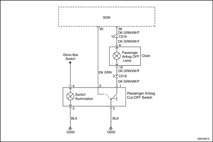
Diagnostic Trouble Code - DTC - B1451
Manual Cut-Off Switch Circuit Defect
Circuit Description
When the ignition switch is turned to ON, the sensing and diagnostic module(SDM) will perform turn-on test to diagnose critical malfunctions within SDM itself.
The SDM continuosly checks the cut-off switch position and circuit defect by letting the regular voltge flow through the cut-off switch circuit and verify the current.
DTC B1451 Will Set When
- The wiring open or short between SDM and cut-off switch.
DTC B1451 - Manual Cut-Off Switch Circuit Defect
Caution : The sensing and diagnostic module(SDM) can maintain sufficient voltage to deploy the airbags and pretensioners for 1 minute after the ignition is OFF and the fuse has been removed. If the airbags and pretensioners are not disconnected, do not begin service until one minute has passed after disconnecting power to SDM. Otherwise, injury could result.
Caution : During service procedure, be very careful when handling the SDM. Never strike or jar the SDM. Never power the supplemental inflatable restraints(SIR) when the SDM is not rigidly attached to the vehicle. All SDM mounting bolts must be carefully tightened , and the arrow on the SDM must be point toward the front of the vehicle to ensure proper operation of the SIR. The SDM could be activated if it is powered when it is not rigidly attached to the vehicle, resulting in unexpected deployment and possible injury.
| Step |
Action |
Value(s) |
Yes |
No |
| 1 |
Confirm the ignition switch "OFF".
Wait for a minute to discharge the SDM charger.
|
-
|
-
|
-
|
| 2 |
Visually inspect the connector and wiring of passenger.
Is the wiring damaged or the connector disconnected?
|
-
|
Go to Step 3
|
Go to Step 4
|
| 3 |
Repair the wiring or connect the connector.
|
-
|
-
|
-
|
| 4 |
- Disconnect the connector of passenger airbag cut-off switch.
- Disconnect the connector of passenger airbag cut-off switch.
- Disconnect the connector of SDM wiring.
- Check the resistance between the terminal 60 of SDM and the terminal 3 of cut-off switch.
Is the resistance about 0(zero) ?
|
≈ 0 Ω
|
Go to Step 5
|
Replace the airbag wiring
|
| 5 |
- Connect the connector of SDM wiring.
- Connect the connector of SDM wiring.
- Confirm the ignition switch "ON".
- Check the current at the terminal 3 of cut-off switch connector.
Is the current higher than 12.5 mA ?
|
12.5 mA
|
Replace the cut-off switch
|
Replace the SDM
|
Diagnostic Trouble Code - DTC - B1453
Vehicle Speed Signal Wrong(Short to Ground)
Circuit Description
When the ignition switch is turned to ON, the sensing and diagnostic module(SDM) will perform turn-on test to diagnose critical malfunctions within SDM itself.
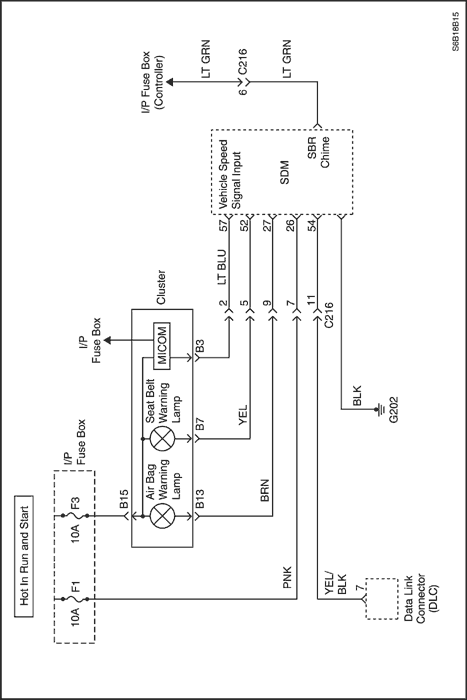
The SDM continuously receive vehicle speed signal from the cluster. If driver seat belt is unbelted, the SDM give the driver such alert as warning lamp and sound according to vehicle status.
DTC B1453 Will Set When
- The SDM can not receive vehicle speed signal from the cluster.
DTC B1453 - Vehicle Speed Signal Wrong - Short to Ground -
Caution : The sensing and diagnostic module(SDM) can maintain sufficient voltage to deploy the airbags and pretensioners for 1 minute after the ignition is OFF and the fuse has been removed. If the airbags and pretensioners are not disconnected, do not begin service until one minute has passed after disconnecting power to SDM. Otherwise, injury could result.
Caution : During service procedure, be very careful when handling the SDM. Never strike or jar the SDM. Never power the supplemental inflatable restraints(SIR) when the SDM is not rigidly attached to the vehicle. All SDM mounting bolts must be carefully tightened , and the arrow on the SDM must be point toward the front of the vehicle to ensure proper operation of the SIR. The SDM could be activated if it is powered when it is not rigidly attached to the vehicle, resulting in unexpected deployment and possible injury.
| Step |
Action |
Value(s) |
Yes |
No |
| 1 |
Visually inspect the the connector and wiring between the SDM and the cluster.
Is the connector disconnected or the wirng damaged?
|
-
|
Replace the wiring or connect the connector.
|
Go to Step 2
|
| 2 |
- Confirm the ignition switch "OFF".
- Wait for a minute the SDM charger to be discharged.
- Disconnect the connector of the cluster.
- Disconnect the connector of SDM.
- Check the resistance between the terminal B14 of cluster wiring and the terminal 57 of SDM wiring.
Is the resistance about 0(zero)?
|
0 Ω
|
Go to Step 3
|
Replace the airbag wiring
|
| 3 |
Check the resistance between the terminal 57 of SDM wiring and the ground.
Is the resistance ∞?
|
∞
|
Go to Step 4
|
Replace the airbag wiring
|
| 4 |
- Replace the cluster.
- Erase the DTC using scan tool.
- Perform the SIR Diangnostic System Check.
Is the DTC removed?
|
-
|
The System is OK
|
Replace the SDM
|
Diagnostic Trouble Code - DTC - B1620
SDM Internal Fault
Circuit Description
When the ignition switch is turned to ON, the sensing and diagnostic module(SDM) will perform turn-on test to diagnose critical malfunctions within SDM itself.
DTC B1620 Will Set When
- The SDM does not implement diagnostic operation. In case of above, the wiring harness of SDM should be checked before replacing the SDM.
DTC B1620 – SDM Internal Fault
Caution : The sensing and diagnostic module(SDM) can maintain sufficient voltage to deploy the airbags and pretensioners for 1 minute after the ignition is OFF and the fuse has been removed. If the airbags and pretensioners are not disconnected, do not begin service until one minute has passed after disconnecting power to SDM. Otherwise, injury could result.
Caution : During service procedure, be very careful when handling the SDM. Never strike or jar the SDM. Never power the supplemental inflatable restraints(SIR) when the SDM is not rigidly attached to the vehicle. All SDM mounting bolts must be carefully tightened , and the arrow on the SDM must be point toward the front of the vehicle to ensure proper operation of the SIR. The SDM could be activated if it is powered when it is not rigidly attached to the vehicle, resulting in unexpected deployment and possible injury.
Diagnostic Trouble Code - DTC - B1650
Frontal Airbag Crash Recorded
Circuit Description
When the ignition switch is turned to ON, the sensing and diagnostic module(SDM) will perform turn-on test to diagnose critical malfunctions within SDM itself.
In case of airbag inflation by a vehicle collision, the SDM maintains warning lamp "ON" and then all the airbag system including SDM, Airbag Module and wiring should be replaced.
DTC B1650 Will Set When
- The history of frontal airbag (driver or passenger) inflation is in the SDM.
DTC B1650 - Frontal Airbag Crash Recorded
Caution : The sensing and diagnostic module(SDM) can maintain sufficient voltage to deploy the airbags and pretensioners for 1 minute after the ignition is OFF and the fuse has been removed. If the airbags and pretensioners are not disconnected, do not begin service until one minute has passed after disconnecting power to SDM. Otherwise, injury could result.
Caution : During service procedure, be very careful when handling the SDM. Never strike or jar the SDM. Never power the supplemental inflatable restraints(SIR) when the SDM is not rigidly attached to the vehicle. All SDM mounting bolts must be carefully tightened , and the arrow on the SDM must be point toward the front of the vehicle to ensure proper operation of the SIR. The SDM could be activated if it is powered when it is not rigidly attached to the vehicle, resulting in unexpected deployment and possible injury.
Diagnostic Trouble Code - DTC - B1651
Driver Side Airbag Crash Recorded
Circuit Description
When the ignition switch is turned to ON, the sensing and diagnostic module(SDM) will perform turn-on test to diagnose critical malfunctions within SDM itself.
In case of driver side airbag inflation by side impact, the SDM maintains warning lamp "ON". The driver belt pretensioner, driver side airbag module, driver side airbag sensor and SDM should be replaced. After replacing these parts, all the airbag system should be checked.
DTC B1651 Will Set When
- The history of driver side airbag inflation is in the SDM.
DTC B1651 - Driver Side Airbag Crash Recorded
Caution : The sensing and diagnostic module(SDM) can maintain sufficient voltage to deploy the airbags and pretensioners for 1 minute after the ignition is OFF and the fuse has been removed. If the airbags and pretensioners are not disconnected, do not begin service until one minute has passed after disconnecting power to SDM. Otherwise, injury could result.
Caution : During service procedure, be very careful when handling the SDM. Never strike or jar the SDM. Never power the supplemental inflatable restraints(SIR) when the SDM is not rigidly attached to the vehicle. All SDM mounting bolts must be carefully tightened , and the arrow on the SDM must be point toward the front of the vehicle to ensure proper operation of the SIR. The SDM could be activated if it is powered when it is not rigidly attached to the vehicle, resulting in unexpected deployment and possible injury.
Diagnostic Trouble Code - DTC - B1652
Passenger Side Airbag Crash Recorded
Circuit Description
When the ignition switch is turned to ON, the sensing and diagnostic module(SDM) will perform turn-on test to diagnose critical malfunctions within SDM itself.
In case of passenger side airbag inflation by side impact, the SDM maintains warning lamp "ON". The passenger belt pretensioner, passenger side airbag module, passenger side airbag sensor and SDM should be replaced. After replacing these parts, all the airbag system should be checked.
DTC B1652 Will Set When
- The history of passenger side airbag inflation is in the SDM.
DTC B1652 - Passenger Side Airbag Crash Recorded
Caution : The sensing and diagnostic module(SDM) can maintain sufficient voltage to deploy the airbags and pretensioners for 1 minute after the ignition is OFF and the fuse has been removed. If the airbags and pretensioners are not disconnected, do not begin service until one minute has passed after disconnecting power to SDM. Otherwise, injury could result.
Caution : During service procedure, be very careful when handling the SDM. Never strike or jar the SDM. Never power the supplemental inflatable restraints(SIR) when the SDM is not rigidly attached to the vehicle. All SDM mounting bolts must be carefully tightened , and the arrow on the SDM must be point toward the front of the vehicle to ensure proper operation of the SIR. The SDM could be activated if it is powered when it is not rigidly attached to the vehicle, resulting in unexpected deployment and possible injury.
Diagnostic Trouble Code - DTC - B1657
Beltpretensioner Crash Recorded
Circuit Description
When the ignition switch is turned to ON, the sensing and diagnostic module(SDM) will perform turn-on test to diagnose critical malfunctions within SDM itself.
In case of belt pretensioner explosion, the SDM maintains warning lamp "ON" and then all the airbag system should be checked and also SDM, pretensioners and wiring should be replaced.
DTC B1657 Will Set When
- The history of belt pretensioner explosion is in the SDM.
DTC B1657 - Beltpretensioner Crash Recorded
Caution : The sensing and diagnostic module(SDM) can maintain sufficient voltage to deploy the airbags and pretensioners for 1 minute after the ignition is OFF and the fuse has been removed. If the airbags and pretensioners are not disconnected, do not begin service until one minute has passed after disconnecting power to SDM. Otherwise, injury could result.
Caution : During service procedure, be very careful when handling the SDM. Never strike or jar the SDM. Never power the supplemental inflatable restraints(SIR) when the SDM is not rigidly attached to the vehicle. All SDM mounting bolts must be carefully tightened , and the arrow on the SDM must be point toward the front of the vehicle to ensure proper operation of the SIR. The SDM could be activated if it is powered when it is not rigidly attached to the vehicle, resulting in unexpected deployment and possible injury.
Diagnostic Trouble Code - DTC - B2500
Airbag Warning Lamp Failure
Circuit Description
When the ignition switch is turned to ON, the sensing and diagnostic module(SDM) will perform turn-on test to diagnose critical malfunctions within SDM itself.
Upon passing these test ignition and deployment loop voltages are measured to ensure that they are within their normal voltage ranges. The SDM monitors the voltages at the driver low and the passenger low to detect shorts to ground or voltage in the deploy loops.
The SDM checks the wiring connection to each inflator by letting the infinitesimal current flow through the internal circuit and verify the resistance. If the warning lamp operates properly "ON" and "OFF", SDM checks the voltage continuously from the warning lamp terminal.
DTC B2500 Will Set When
- The warning lamp does not blinking properly "ON" and "OFF".
Reference
When the ignition switch is turned ON, in case of normal, the warning lamp blinking 6 times during 6 seconds.
But in case, the warning lamp stays "ON" or blinking a second after above normal blinking(6 times during 6 seconds), then it is regarded as a defect(old or current) presents. Please check the defect with scan tool.
DTC B2500 – Airbag Warning Lamp Failure
Caution : The sensing and diagnostic module(SDM) can maintain sufficient voltage to deploy the airbags and pretensioners for 1 minute after the ignition is OFF and the fuse has been removed. If the airbags and pretensioners are not disconnected, do not begin service until one minute has passed after disconnecting power to SDM. Otherwise, injury could result.
Caution : During service procedure, be very careful when handling the SDM. Never strike or jar the SDM. Never power the supplemental inflatable restraints(SIR) when the SDM is not rigidly attached to the vehicle. All SDM mounting bolts must be carefully tightened , and the arrow on the SDM must be point toward the front of the vehicle to ensure proper operation of the SIR. The SDM could be activated if it is powered when it is not rigidly attached to the vehicle, resulting in unexpected deployment and possible injury.
| Step |
Action |
Value(s) |
Yes |
No |
| 1 |
Check the fuse F3.
Is the fuse blown?
|
-
|
Go to Step 2
|
Go to Step 3
|
| 2 |
Replace the fuse F3.
|
-
|
-
|
-
|
| 3 |
- Confirm the ignition switch "ON".
- Confirm the ignition switch "ON".
- Check the voltage from the fuse F3.
Is the voltage in the range of 11-14V?
|
11~14V
|
Go to Step 5
|
Go to Step 4
|
| 4 |
Repair the power supply and the wiring to the fuse F3.
|
-
|
-
|
-
|
| 5 |
- Confirm the ignition switch "OFF".
- Confirm the ignition switch "OFF".
- Remove the instrument cluster.
- Check the bulb of airbag warning lamp.
Is the bulb OK?
|
-
|
Go to Step 7
|
Go to Step 6
|
| 6 |
Replace the bulb of airbag warning lamp.
|
-
|
-
|
-
|
| 7 |
- Confirm the ignition switch "ON".
- Confirm the ignition switch "ON".
- Check the voltage from the terminal B15 from the wiring connector of cluster.
Is the voltage in the range of 11~14V?
|
≈ 11~14V
|
Go to Step 9
|
Go to Step 8
|
| 8 |
Repair the wire between the fuse F3 and the terminal B15 from the wiring connector of cluster.
|
-
|
-
|
-
|
| 9 |
Check the connection between the terminal B15 and B13 from the cluster.
Is the connection OK?
|
-
|
Go to Step 11
|
Go to Step 10
|
| 10 |
Replace the instrument cluster.
|
-
|
-
|
-
|
| 11 |
- Confirm the ignition switch "OFF".
- Confirm the ignition switch "OFF".
- Remove the connector of passenger airbag module and the connector of clock spring.
- Remove the connector of SDM.
- Confirm the ignition switch "OFF".
- Confirm the ignition switch "OFF".
- Check the voltage from the terminal 27 of SDM wiring.
- Check the voltage from the terminal 27 of SDM wiring.
Is the voltage in the range of 11~14V?
|
-
|
Replace the SDM.
|
Go to Step 12
|
| 12 |
Repair the wiring between the terminal 27 of SDM and the instrument cluster.
|
-
|
-
|
-
|
Diagnostic Trouble Code - DTC - B2502
Passenger Airbag "OFF" Indicator Failure
Circuit Description
When the ignition switch is turned to ON, the sensing and diagnostic module(SDM) will perform turn-on test to diagnose critical malfunctions within SDM itself.
The SDM continuosly checks the cut-off switch position and circuit defect by letting the rehular voltge flow through the cut-off switch circuit and verify the current.
DTC B2502 Will Set When
- The warning lamp does not blinking properly "ON" and "OFF".
DTC B2502 – Passenger Airbag "OFF" Indicator Failure
Caution : The sensing and diagnostic module(SDM) can maintain sufficient voltage to deploy the airbags and pretensioners for 1 minute after the ignition is OFF and the fuse has been removed. If the airbags and pretensioners are not disconnected, do not begin service until one minute has passed after disconnecting power to SDM. Otherwise, injury could result.
Caution : During service procedure, be very careful when handling the SDM. Never strike or jar the SDM. Never power the supplemental inflatable restraints(SIR) when the SDM is not rigidly attached to the vehicle. All SDM mounting bolts must be carefully tightened , and the arrow on the SDM must be point toward the front of the vehicle to ensure proper operation of the SIR. The SDM could be activated if it is powered when it is not rigidly attached to the vehicle, resulting in unexpected deployment and possible injury.
| Step |
Action |
Value(s) |
Yes |
No |
| 1 |
- Confirm the ignition switch "OFF".
- Visually inspect the connector and wiring of passenger airbag cut-off switch.
Is the wiring damaged or the connector disconnected?
|
-
|
Go to Step 2
|
Go to Step 3
|
| 2 |
Repair the wiring or connect the connector.
|
-
|
-
|
-
|
| 3 |
- Remove the clock.
- Remove the clock.
- Check the bulb of passenger airbag off lamp.
Is the bulb OK?
|
-
|
Go to Step 5
|
Go to Step 4
|
| 4 |
Replace the bulb of passenger airbag off lamp.
|
-
|
-
|
-
|
| 5 |
Check the connection between the terminal 6 and 10 of clock.
Is the connection OK?
|
-
|
Go to Step 7
|
Go to Step 6
|
| 6 |
Replace the clock.
|
-
|
-
|
-
|
| 7 |
- Confirm the ignition switch "ON".
- Confirm the ignition switch "ON".
- Disconnect the connector of clock.
- Check the voltage at terminal 6 of clock wiring.
Is the voltage 4.75-5.25 V ?
|
4.75 - 5.25V
|
Go to Step 9
|
Go to Step 8
|
| 8 |
Repair the wiring between the terminal 56 of SDM and the terminal 6 of clock.
|
-
|
-
|
-
|
| 9 |
- Disconnect the connector of passenger airbag cut-off switch.
- Check the resistance between the terminal 10 of clock and the terminal 1 of cut-off switch.
Is the resistance about 0(zero)?
|
≈ 0 Ω
|
Go to Step 11
|
Go to Step 10
|
| 10 |
Repair the wiring between the terminal 10 of clock and the terminal 1 of cut-off switch.
|
-
|
-
|
-
|
| 11 |
Replace the SDM.
|
-
|
-
|
-
|
 |
|
 |
|
| © Copyright Chevrolet Europe. All rights reserved |