GENERAL DESCRIPTION AND SYSTEM OPERATION
Supplemental Inflatable Restraints - SIR -
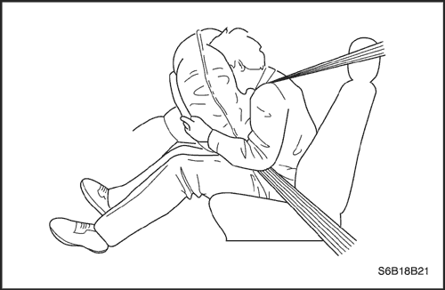
The supplemental inflatable restraints(SIR) is a safety device used in conjunction with the seat belt. The air bag does not replace the fuction of the seatbelt. The driver and the passengers must always fasten their seat belts and adjust them for a proper fit.
The SIR is designed to protect the driver and the front seat passenger in the event of a significant frontal impact to the vehicle. The airbags deploy if the force is applied from a direction within 30 degrees of the vehicle's center line.
The SIR system consists of a
- Driver airbag module
- Driver side airbag module
- Passenger airbag module
- Passenger side airbag module
- Driver's and front passenger's seat belt pretensioners(and load limiter for some model).
- Sensing and diagnostic module(SDM)
- Clock spring.
- Wire harness and connectors.
- AIRBAG indicator on the instrument cluster.
- Side airbag sensor


Airbag Modules
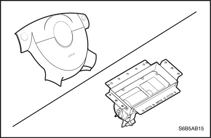
Driver Airbag Module
Caution : Tempering with driver airbag module creates the risk of an injury from unexpected deployments. Therefore, the driver airbag module should never be disassembled.
The driver airbag module is under the center pad of the steering wheel. The driver airbag module contained an igniter charge and a gas generator to inflate the folded airbag.
The airbag connector contains a shorting bar, which makes the circuit shorted when the connector is disconnected. The shorting bar prevents current from travelling through the driver airbag module during servicing. The shorting bar is disengaged when the connector is connected.
Passenger Airbag Module
Caution : Tempering with passenger airbag module creates the risk of an injury from unexpected deplyment. Therefore, the passenger airbag module should never be disassembled.
The passenger airbag module is on the passenger part of the instrument panel. The passenger airbag module contains an igniter charge and a gas generator to inflate the folded airbag .
The passenger airbag module is on the passenger part of the instrument panel. The passenger airbag module contains an igniter charge and a gas generator to inflate the folded airbag .
Side Airbag Module
Caution : Tempering with side airbag module creates the risk of an injury from unexpected deployments. Therefore, the driver airbag module should never be disassembled.
The side airbag modules are in the driver's and passenger's seats. The side airbag module contains an igniter charge and a gas generator to inflate the folded airbag .
Front Seat Belt Pretensioners
Caution : Tempering with seat belt pretensioner creates the risk of an injury from unexpected deployment. Therefore, the driver airbag module should never be disassembled.
The seat belt pretensioners(with load limiter for some vehicles) are assembled with each front seat belt retractors to retract the seat belt webbing when accounted frontal collision. The seat belt pretensioners are controlled by sensing and diagnostic module(SDM). The seat belt pretensioner contains an igniter charge and a gas generator to pull the seat belt webbing. The seat belt pretensioner must be replaced after an accident that causes its activation.
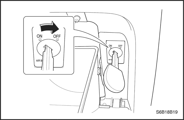
Passenger Airbag Manual Cut-Off Switch
The cut-off switch is located on right side of glove box housing. Operation of passenger frontal and side airbag can be controlled manunally by this switch. Operation of cut-off switch use the ignition key of vehicle. If cut-off switch is turned into "ON" or "OFF" using the ignition key, passenger frontal and side airbag also will be "ON" or "OFF".
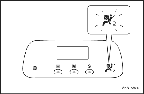
Passenger Airbag "OFF" Lamp
The operation status of passenger frontal and side airbag is displayed on the passenger airbag "OFF" lamp that is located on clock. If the passenger airbag cut-off switch is turned into "OFF" position, passenger airbag "OFF" lamp will be turned on.
In cut-off switch "ON" position, passenger airbag "OFF" lamp will be turned off.
Sensing and Diagnostic Module - SDM -
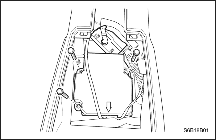
Caution : During the service procedures, be careful when handling the SDM. Never shake or jar the SDM. Never apply power to SIR when the SDM is not rigidly attached to the vehicle. All SDM mounting bolts and grounding nuts must be fully tightened. Failure to follow these precautions could cause deployment and result in personal injury.
The SDM is located on the floor beneath the floor console assembly. The SDM performs the following functions :
- Monitors the supplemental inflatable restraints(SIR) electrical components and sets a diagnostic trouble code(DTC) when malfunction is detected.
- Records any faults that are discovered.
- Displays SIR diagnostic trouble codes and system status information when connected to a scan tool.
- Illuminates the airbag indicator to alert the driver to any fault.
- Provides a reserve power source to deploy the airbags and pretensioners if an accident has disabled the normal power source.
- Monitors vehicle velocity changes to detect frontal impacts, which are severe enough to warrant deployment.
- Causes current to flow through the airbag modules and pretensioner to cause deployment if a frontal impact of sufficient force is detected.
The SDM contains no user-serviceable parts.
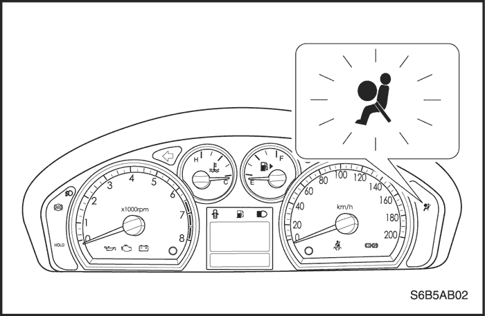
Airbag Warning lamp
The instrument cluster contains an airbag warning indicator and sensing and diagnostic module(SDM). The SDM performs a turn-on test when the ignition is turned ON.
The SDM flashes the airbag indicator six times by supplying an intermittent ground to the indicator lamp circuit. After flashing six times, the airbag indicator will turn off if no more malfunctions have been detected.
If the SDM has detected malfunctions in the internal and external circuits, which could potentially affect the operation of the supplemental inflatable restraints(SIR), the airbag indicator stays on. Some malfunctions could result in non-deployment when necessary or deployment under conditions which would not normally result in deployment.
When the SDM is not properly attached to its connector, the airbag circuit is shorted to ground because there is a shorting bar in the SDM electrical connector. The shorting bar is disengaged when proper connection is made, but if a poor connection exists the SDM connector supplied a ground to the airbag indicator independently of the SDM, and the airbag indicator turns on.
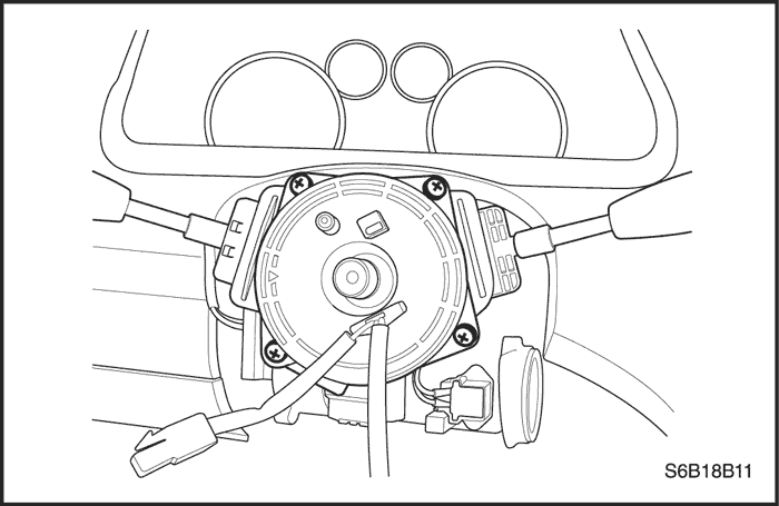
Clock Spring
Caution : Disassembling the clock spring can cause injury or cause the clock spring to malfunction.
Caution : Over-rotating the clock spring (over 3 and one quarter turns to one direction) without the steering wheel in position could damage the clock spring and result in an inoperative driver airbag.
There is a coil assembly in the steering which is referred to as a clock spring because of its internal resemblance to the type of spring used in a mechanical clock. The coil spring should never be disassembled, and there is no timekeeping function. The clock spring contains two or three current-carrying coils. One of the current-carrying coils maintains continuous contact within the driver deployment loop while the steering wheel is rotated. The clock spring also contains coils that maintain continuous contact for horn and remote audio control switch circuit.
Turning the steering wheel in one direction tightens the coil, and turning the steering wheel in the opposite direction loosens the coil. Do not turn the clock spring when the steering wheel is not attached. Refer to
"Clock Spring"
in this section for proper installation of the clock spring.
The clock spring also includes the wiring and the connectors for the horn circuit and the driver airbag circuit. A yellow two-way connector on the lower steering column is attached to the clock spring wiring.
Wiring Harness Connectors
If the sensing and diagnostic module (SDM) electrical connector is not attached properly, a built in shorting bar will connect the wire from airbag warning lamp with the SDM ground wire. This turns on the airbag indicator.
The shorting bar is only a backup safety device. Always disable the supplemental inflatable restraints(SIR) before beginning any service procedure.
| © Copyright Chevrolet Europe. All rights reserved |


