MAINTENANCE AND REPAIR
ON-VEHICLE SERVICE
SERVICE PRECAUTION
Caution : The sensing and diagnostic module(SDM) can maintain sufficient voltage to deploy the airbags and pretensioners for 1 minute after the ignition is OFF and the fuse has been removed. If the airbags and pretensioners are not disconnected, do not begin service until one minute has passed after disconnecting power to SDM. If the airbags are disconnected, service can be executed immediately without waiting for one-minute time period to expire. Failure to temporarily disable the SIR during service can result in unexpected deployment, personal injury and unnecessary SIR repairs.
Disabling the Supplemental Inflatable Restraints - SIR -
- Turn the steering wheel to the straight-ahead position.
- Turn the ignition switch to LOCK and remove the key.
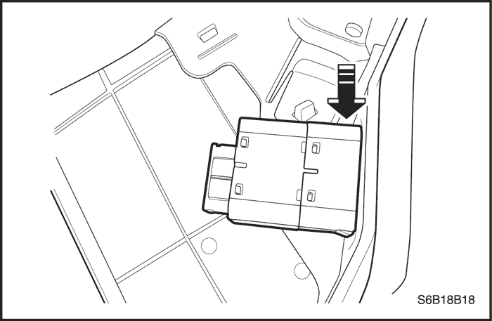
- Remove the airbag fuse F1 in the I/P fuse block and wait more than one minute for SIR capacitor to discharge
Enabling the Supplemental Inflatable Restraints - SIR -
- Insert the airbag fuse F1 in the I/P fuse block.
- Turn the ignition switch to ON and verify that the airbag indicator flashes six times and turns OFF. If it does not operate as described, perform the" SIR Diagnostic System Check" referring in this section.
Caution : While turning the ignition switch, staying well away from the inflator modules, or personal injury can be occurred.
Handling, Installation and Diagnosis
- Airbag modules should not be subjected to temperature above 65 degrees Celsius(149 degrees Fahrenheit).
- An airbag and SDM should not be used if it has been dropped from height of 0.9 meters(3 feet) or greater.
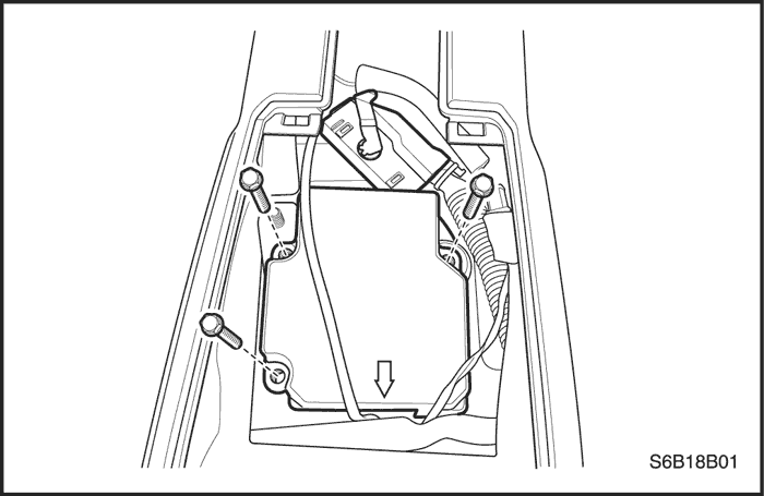
- When an SDM is replaced, it must be oriented with the arrow on the SDM pointing toward the front of the vehicle.
- It is very important for the SDM to be installed flat on the mounting surface, parallel to the vehicle's longitudinal axis.
- To avoid setting diagnostic trouble codes(DTCs), do not apply power to the SIR unless all components are connected or a diagnostic chart request it.
- The SIR Diagnostic System Check must be the starting point of any SIR diagnostics. The SIR Diagnostic System Check will verify proper airbag indicator operation and will lead you to correct chart to diagnose any SIR malfunctions. Bypassing these procedures may result in extended diagnostic time and incorrect parts replacement.
Repairs and Inspections Required After an Accident
Caution : Any repairs to the vehicle's structure must return it to the original production configuration. Deployment requires replacement of SDM, the inflator modules and a dimensional inspection of the steering column.
- If any SIR components are damaged, they must be replaced. If SIR components mounting points are damaged, they must be repaired or replaced.
- Never use SIR parts from another vehicle. This does not include remanufactured parts purchased from an authorized source.
- Do not attempt to service the SDM, the clock spring or other airbag modules, these items must be replaced if they are defective.
- Verify the part number of replaced airbag modules. Some inflator modules look identical but contain different internal components.
Accident With Deployment Components Replacements
All SIR components must be replaced after frontal crash involving airbag deployment. After deployment, a powdery residue may be on the surface of the airbag. The powder consists primarily of cornstarch(used to lubricate the bag as it inflates) and by-products of the chemical reaction. The sodium hydroxide then quickly reacts with atmospheric moisture and is converted to sodium bicarbonate(also known as baking soda). Therefore, it is unlikely that sodium hydroxide will be present after deployment. Replace the following SIR components.
Caution : Wear gloves and safely glasses during the disposal procedure. Refer to "Deployed airbag module disposal procedure" in this section.
- The SDM
- Airbag modules and pretensioners
- SIR wiring
- Clock spring
Accident Without Deployment Component Inspection
Certain inspection must be performed after any crash, whether the airbag has deployed or not. :
- The steering column must be dimensionally inspected.
- Inspect the knee bolsters and mounting points for distortion, bending and cracking or other damages.
- Inspect the instrument panel(I/P) and steering column reinforcement plate for distorsion, bending and cracking or other damage.
- Inspect the I/P braces for distortion, bending and cracking or other damage.
- Inspect the seat belt and mounting points. Refer to Section 8A, Seat Belts.
Sensing and Diagnostic Module - SDM -
Caution : During service procedure, be very careful when handling the SDM. Never strike or jar the SDM. Never power the supplemental inflatable restraints(SIR) when the SDM is not rigidly attached to the vehicle. All SDM mounting bolts must be carefully tightened , and the arrow on the SDM must be point toward the front of the vehicle to ensure proper operation of the SIR. The SDM could be activated if it is powered when it is not rigidly attached to the vehicle, resulting in unexpected deployment and possible injury.
Important : If the vehicle interior has been exposed to extensive water intrusion such as water leaks, driving through high water, flooding or other causes, then the SDM and SDM connector may need to be replaced. With the ignition OFF, inspect the area of SDM, including the carpet. If any significant soaking or evidence of previous soaking is detected, the water must be removed, the water damage repaired and the SDM and SDM connector must be replaced. Before attempting any of these repairs, the SIR must be disabled. Refer to "Disabling the SIR"
in this section.


Removal Procedure
- Disable the supplemental inflatable restraints(SIR). Refer to "Disabling the SIR"
in this section.
- Remove the floor console cover. Refer to Section 9G, Interior Trim.
- Remove the connector position assurance lock, which is tethered to SDM connector.
- Disconnect the SDM electrical connector.
- Remove the SDM mounting bolts.
- Remove the SDM.
Installation Procedure
- Install the SDM with the arrow pointing toward the front of the vehicle.
- Install the SDM mounting bolts.
Tighten
Tighten the SDM mounting bolts to 14 N•m (10 lb-ft)
- Connect the SDM electrical connector.
- Install the connector position assurance lock.
- Install the floor console cover. Refer to Section 9G, Interior Trim.
- Enable the SIR. Refer to "Enabling the SIR"
in this section.
Caution : All SDM mounting bolts must be carefully tightened and the arrow on the SDM must be pointing toward the front of the vehicle to ensure proper operation of the SIR. The SDM could be activated if it is powered while not rigidly attached to the vehicle, resulting in unexpected deployment and possible injury.
Driver Airbag Module
Removal Procedure
- Disconnect the negative battery cable.
Caution : The sensing and diagnostic module(SDM) can maintain sufficient voltage to deploy the airbags and pretensioners for 1 minute after the ignition is OFF and the fuse has been removed. If the airbags and pretensioners are not disconnected, do not begin service until one minute has passed after disconnecting power to SDM. If the airbags are disconnected, service can be executed immediately without waiting for one-minute time period to expire. Failure to temporarily disable the SIR during service can result in unexpected deployment, personal injury and unnecessary SIR repairs.
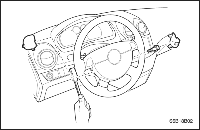
- Position the steering wheel straight ahead.
Caution : When handling an airbag module, always keep the top of the unit facing upward. This leaves room for the airbag to expand if the module unexpectedly deploys. Without room for expansion, a module suddenly propelled toward a person or object can cause injury or vehicle damage.
- Remove two driver airbag module mounting bolts and discard them.
- Remove the connectors from the horn terminal and the driver airbag module.
- Remove the driver airbag module.
Installation Procedure
Caution : When handling an airbag module, always keep the top of the unit facing upward. This leaves room for the airbag to expand if the module unexpectedly deploys. Without room for expansion, a module suddenly propelled toward a person or object can cause injury or vehicle damage.
- Install the connectors to the horn terminal and the driver airbag module.
- Install the driver airbag module.
- Install the driver airbag module mounting bolts.
Tighten
Tighten the driver airbag module mounting bolts to 15 N•m (11lb-ft).
- Connect the negative battery cable.
Clock Spring
Removal Procedure
Caution : The sensing and diagnostic module(SDM) can maintain sufficient voltage to deploy the airbags and pretensioners for 1 minute after the ignition is OFF and the fuse has been removed. If the airbags and pretensioners are not disconnected, do not begin service until one minute has passed after disconnecting power to SDM. If the airbags are disconnected, service can be executed immediately without waiting for one-minute time period to expire. Failure to temporarily disable the SIR during service can result in unexpected deployment, personal injury and unnecessary SIR repairs.
- Disconnect the negative battery cable.
- Remove the driver airbag module. Refer to "Driver airbag module"
in this section.
- Remove the steering wheel. Refer to Section 6E, Steering Wheel and Column.
- Remove the upper and lower steering column cover panel. Refer to Section 6E, Steering Wheel and Column.
- Remove the driver knee bolster. Refer to Section 9E, Instrumentaion/Driver Information.
- Disconnect the driver airbag, horn connectors from the lower steering column.
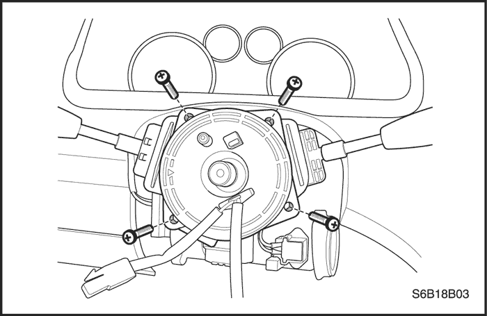
- Remove the screws and discard them.
- Remove the clock spring from the steering shaft.
Installation Procedure
Caution : If the clock spring is not properly aligned, the steering wheel may not be able to rotate completely during a turn. Restricted turning ability can cause the vehicle to crash. Improper alignment of the clock spring also may make the SIR inoperative, preventing the airbag from deploying during crash. Both of the outcomes can result in injury.
Notice : Turning the clock spring more than three turns clockwise or counterclockwise can damage the spring.
- Turn the front wheels straight ahead.
- Install the clock spring with the screws.
Tighten
Tighten the clock spring mounting screws to 1.25 N•m (11 lb-in).
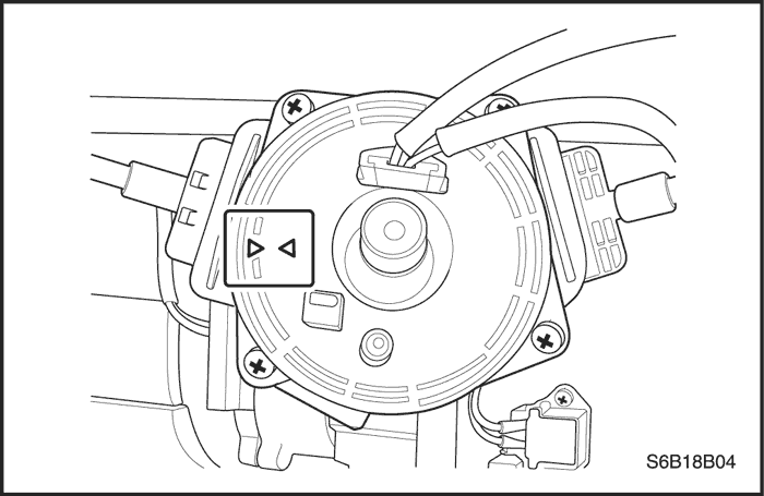
- Turn the lobe of clock spring clockwise to lock (Do not force).
- Then turn the lobe of clock spring counterclockwise approximately three turns to the neutral position, with the front of the wheels straight ahead.
- Properly align the pointed marks on the components of the clock spring.
- Connect the connectors on the lower steering column.
- Install the driver knee bolster. Refer to Section 9E, Instrumentaion/Driver Information.
- Install the upeer and lower steering column cover panel. Refer to Section 6E, Steering Wheel and Column.
- Install the steering wheel.
- Install the driver airbag module. Refer to "Driver Airbag Module" in this section.
- Connect the negative battery cable.
Passenger Airbag Module
Removal Procedure
Caution : The sensing and diagnostic module(SDM) can maintain sufficient voltage to deploy the airbags and pretensioners for 1minute after the ignition is OFF and the fuse has been removed. If the airbags and pretensioners are not disconnected, do not begin service until one minute has passed after disconnecting power to SDM. If the airbags are disconnected, service can be excuted immediately without waiting for one-minute time period to expire. Failure to temporarily disable the SIR during service can result in unexpected deployment, personal injury and unnecessary SIR repairs.
- Disconnect the negative battery cable.
- Remove the glove box. Refer to Section 9E, Instrumentaion/Driver Information.
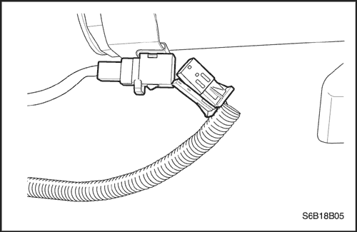
- Disconnect the passenger airbag yellow electrical connector.
- Remove the instrument panel. Refer to Section 9E, Instrumentaion/Driver Information.
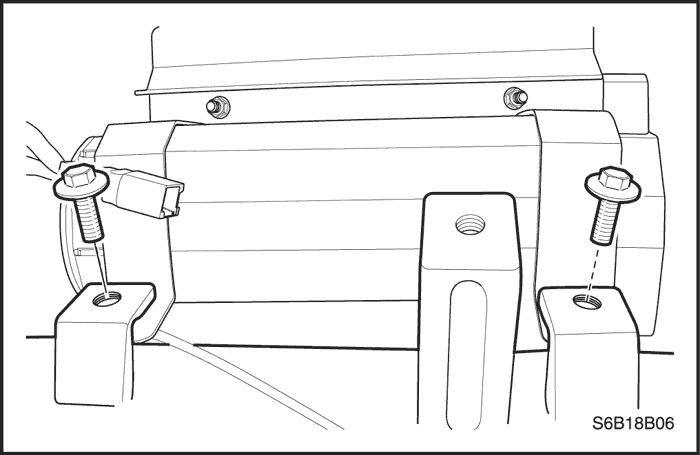
- Remove the mounting bolts from the tie bar.
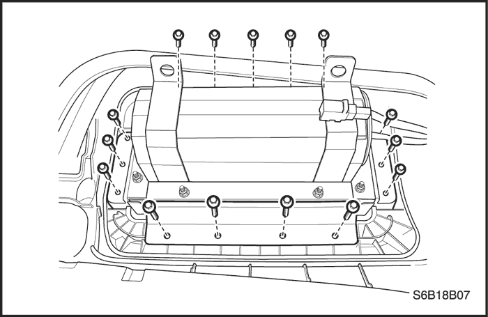
- Remove the passenger airbag module by removing the mounting bolts from the upper instrument panel.
Installation Procedure
- Install the passenger airbag module.
- Install the passenger airbag mounting bolts to the tie bar.
Tighten
Tighten the passenger airbag mounting bolts to 15 N•m (11 lb-ft).
- Install the passenger airbag mounting bolts to the upper instrument panel.
Tighten
Tighten the passenger airbag mounting bolts to 6 N•m (53 lb-in).
- Install the instrument panel. Refer to Section 9E, Instrumentaion/Driver Information.
- Connect the passenger airbag yellow electrical connector.
- Install the glove box. Refer to Section 9E, Instrumentaion/Driver Information.
- Connect the negative battery cable.
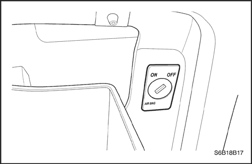
Passenger Airbag Cut-OFF Switch
Removal Procedure
- Disconnect the negative battery cable.
- Open the glove box and disconnect the connector of cut-off switch in the instrument panel.
- Remove the cut-off switch by pushing the tab on upper side of switch housing.
Installation Procedure
- Install the cut-off switch on the glove box housing.
- Connect the connector of cut-off switch.
- Connect the negative battery cable.
Side Airbag Sensor
Removal Procedure
Caution : The sensing and diagnostic module(SDM) can maintain sufficient voltage to deploy the airbags and pretensioners for 1minute after the ignition is OFF and the fuse has been removed. If the airbags and pretensioners are not disconnected, do not begin service until one minute has passed after disconnecting power to SDM. If the airbags are disconnected, service can be executed immediately without waiting for one-minute time period to expire. Failure to temporarily disable the SIR during service can result in unexpected deployment, personal injury and unnecessary SIR repairs.
- Disconnect the negative battery cable.
- Remove the lower B-pillar trim panel. Refer to Section 9G, Interior Trim.
- Disconnect the electrical connector.
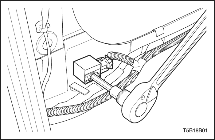
- Remove the side airbag sensor mounting bolt.
- Remove the side airbag sensor.
Installation Procedure
- Install the side airbag sensor.
- Install the side airbag sensor mounting bolt.
Tighten
Tighten the side airbag sensor mounting bolt to 10 N•m (89 lb-in).
- Connect the electrical connector.
- Install the lower B-pillar trim panel. Refer to Section 9G, Interior Trim.
- Connect the negative battery cable.
Front Seat Belt Pretensioner
Airbag Module Deployment - Inside of Vehicle -
Deploy the airbags before disposing them. If a vehicle to be scrapped, the airbag may be deployed inside the vehicle.
Caution : To avoid injury while deploying an airbag or a pretensioner in the vehicle, observe the following precaution :
- Before deploying the airbags, remove all loose objects from the airbag's expansion area.
- Deploy the airbags with the vehicle doors closed and the side windows open.
- Deploy the airbags only in an evacuated area. Service personnel who must be present during the deployment should be at least 10 meters(33 feet) in front of the vehicle.
- Do not connect the voltage source until after having completed all other preparations for the deployment of airbags.
- Allow a deployed airbag module or pretensioner cool for 30 minutes before handling.
- Wear gloves and eye protection during the disposal procedure.
- If the deployment fails, disconnect the voltage source and wait 5 minutes before approaching the vehicle.
Deployment Procedure
Caution : The sensing and diagnostic module(SDM) can maintain sufficient voltage to deploy the airbags and pretensioners for 1 minute after the ignition is OFF and the fuse has been removed. If the airbags and pretensioners are not disconnected, do not begin service until one minute has passed after disconnecting power to SDM. If the airbags are disconnected, service can be executed immediately without waiting for one-minute time period to expire. Failure to temporarily disable the SIR during service can result in unexpected deployment, personal injury and unnecessary SIR repairs.
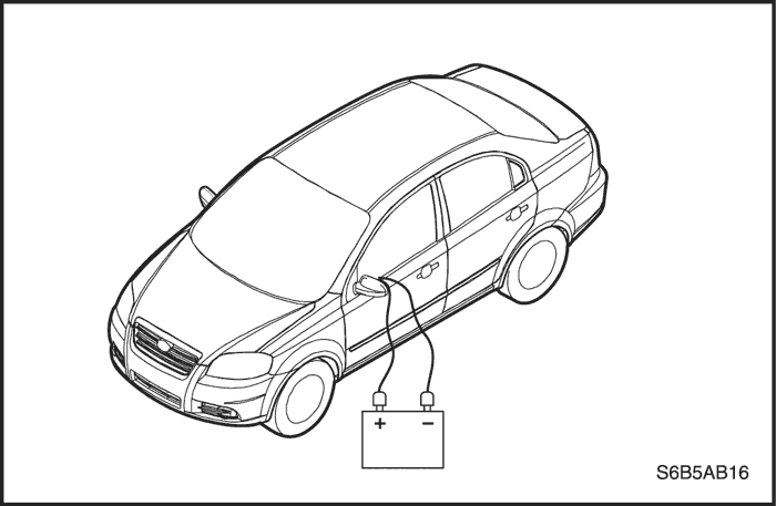
- Disconnect both battery cables and place the battery at least 10 meters (33 feet) from the vehicle.
- Remove the driver side knee bolster or instrument panel lower cover from the steering column. Refer to Section 9G, Interior Trim.
- At the lower steering column, cut the two wires leading from the supplemental inflatable restraints(SIR) harness to the clock spring.
- Strip 13mm(0.5 inch) of the insulation from the end of the wires leading to the clock spring.
- Use two additional wires, each at least 10 meters(33 feet) long, to reach from the deployment battery to the inflator module.
- Strip 13mm(0.5 inch) of the insulation from the end of these two additional wires.
- Twist the two wires together at one end.
- Twist the two wires together at one end.
- Place the twisted ends of the two wires near the deployment battery. Do not connect the wires to the battery at this time.
- Using the free ends of the 10 meters(33 feet) wires leading to the clock spring, make two splices, one at each wires from the airbag modules.
- Wrap the wires with insulation tape.
- Now that the free ends of the 10 meters(33 feet) wires are spliced to the airbag module wires, and the ends that are twisted together are near the deployment battery. Clear the area.
- Untwist the wires that near the deployment battery.
- Touch one wire to the positive battery terminal and touch the other wire to the negative battery terminal. The airbag will deploy.
- Repeat this procedure for the passenger airbag, side airbags and pretensioners.
- Using proper precautions, dispose of the deployed airbags/pretensioners. Refer to "Deployed Airbag Module Disposal Procedure"
in this section.
Airbag Module Deployment - Outside of Vehicle -
If the vehicle is within the warranty period, contact the Daewoo regional service manager for approval or special instructions before deploying the airbag modules.
Deploy airbag modules in following situations :
Caution : To avoid injury while deploying an airbag or a pretensioner outside the vehicle, observe the following precaution :
- Deploy the airbags only in an evacuated area. Service personnel who must be present during the deployment should be at least 10 meters(33 feet) in front of the vehicle.
- Do not connect the voltage source until after having completed all other preparations for the deployment of airbags.
- Allow a deployed airbag module or pretensioner cool for 30 minutes before handling.
- Wear gloves and eye protection during the disposal procedure.
- If the deployment fails, disconnect the voltage source and wait 5 minutes before approaching the vehicle.
- Position the airbag module face up, on flat ground outdoors, at least 10 meters(33 feet) from the any obstacles or people.
- Use two additional wires, each at least 10 meters(33 feet) long, to reach from the deployment battery to the airbag module/pretensioner.
- Strip 13mm(0.5 inch) of the insulation from the ends of these two additional wires.
- Twist the two wires together at one end.
- Place the twisted ends of the two wires near the deployment battery. Do not connect the wires to the battery at this time.
- Using the free ends of the 10 meters(33 feet) wires leading to the airbag module/pretensioner, make two splices, one at each wires from the airbag module/pretensioner.
- Wrap the splices with insulating tape.
- Now that the free ends of the 10 meters(33 feet) wires are spliced to the airbag module/pretensioner wires, and the ends that are twisted together are near the deployment battery, clear the area.
- Untwist the wires that near the deployment battery.
- Touch one wire to the positive battery terminal and touch the other wire to the negative battery terminal. The airbag will deploy.
- Using proper precautions, dispose of the deployed airbags/pretensioners. Refer to "Deployed Airbag Module Disposal Procedure"
in this section.
Deployed Airbag Module disposal Procedure
Caution : After deployment, a powdery residue may be on the surface of the airbag. The powder primarily consists of cornstarch(used to lubricate the bag as it inflates) and by-products of the chemical reaction. The sodium hydroxide then quickly reacts with atmospheric moisture and is converted to sodium carbonate and sodium bicarbonate(also known as baking soda). Therefore, it is unlikely that sodium hydroxide will be presents after deployment.
Caution : Be sure to wear gloves and eye protection during the disposal procedure.
Caution : After deployment, the metal surfaces of the airbag module will be hot. In order to avoid the risk of an injury or a fire do not place the deployed airbag module near any flammable objects, and allow the airbag module to cool for 30 minutes before handling.
Deploy an airbag or pretensioner before disposing of it.
This includes those in a whole vehicle being scrapped. If the vehicle is still within the warranty period contact the Daewoo regional service manager for approval or special instructions before deploying an airbag module or a pretensioner. Deployed airbag module or pretensioner should be disposed of in the same manner as other scrap parts, with the addition of the following steps :
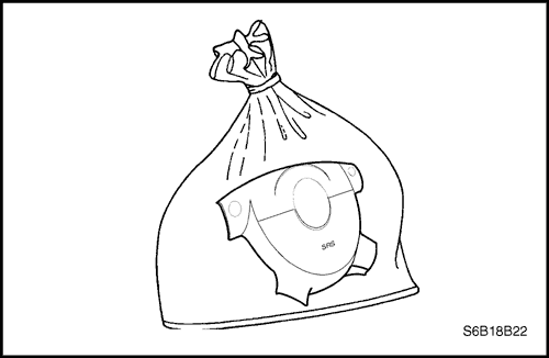
- Place the deployed airbag or pretensioner in a sturdy plastic bag.
- Seal the plastic bag securely.
- Wash your hands and rinse them with water after handling a deployed airbag.
SIR Wiring Repair
Connector Repair
Caution : Before attempting any repairs, the SIR must be disabled. Refer to "Disabling the SIR" in this section for instructions on how to disable the SIR.
The terminals in the SIR are made of special metal to provide necessary contact integrity for the sensitive, low energy circuits. Do not repair any connectors of the SIR. Replace any damaged connectors and wirings which are connected to connectors with new one.
Wire Repair
Caution : Before attempting any repairs, the SIR must be disabled. Refer to "Disabling the SIR" in this section for instructions on how to disable the SIR.
Do not repair any wires of supplemental inflatable restraints(SIR). Replace any damaged wires with new one.
| © Copyright Chevrolet Europe. All rights reserved |


