Aveo |
||||||||
|
||||||||
|
Bulb
|
Replacement Bulb Number
|
|
Backup Lamp
|
21W
|
|
Center High-Mounted Stoplamp
|
5W
|
|
Front Fog Lamp
|
55W (H3)
|
|
Headlamp
|
60/55W (H4)
|
|
Interior Courtesy Lamp
|
10W
|
|
License Plate Lamp
|
5W
|
|
Luggage Compartment Lamp
|
10W
|
|
Park Lamp
|
5W
|
|
Park and Front Turn Signal Lamp
|
21W
|
|
Rear Turn Signal Lamp
|
21W
|
|
Side Turn Signal Lamps
|
5W
|
|
Tail and Stoplamp
|
21/5W
|
|
Application
|
N•m
|
Lb-Ft
|
Lb-In
|
|
CHMSL Mounting Screws
|
3
|
-
|
27
|
|
Door Jamb Switch Screw
|
4.5
|
-
|
40
|
|
Headlamp Assembly Bolts
|
4
|
-
|
35
|
|
Interior Courtesy Lamp Housing Screws
|
2
|
-
|
18
|
|
License Plate Lamp Screws
|
1.5
|
-
|
13
|
|
Taillamp Assembly Screws
|
3
|
-
|
27
|
|
Fog Lamp Assembly Screws
|
5
|
-
|
44
|

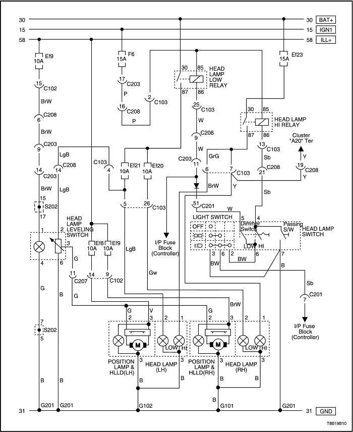

| Step | Action | Value(s) | Yes | No |
| 1 |
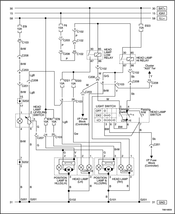
Check fuses Ef21 (left-side headlamps) and Ef20 (right-side headlamps).
Is fuse Ef21 or Ef20 blown?
|
-
|
Go to Step 2
|
Go to Step 3
|
| 2 |
Is the repair complete?
|
-
|
System OK
|
-
|
| 3 |
Check the voltage at fuses Ef21 and Ef20.
Does the voltage available at fuses Ef21 and Ef20 equal the value specified?
|
11-14 v
|
Go to Step 14
|
Go to Step 4
|
| 4 |
Temporarily substitute the illumination lamp relay in place of the headlamp low relay.
Do the headlamps operate with the substituted relay?
|
-
|
Go to Step 5
|
Go to Step 6
|
| 5 |
Reinstall the illumination lamp relay in its original position, and install a new headlamp relay.
Is the repair complete?
|
-
|
System OK
|
-
|
| 6 |
Does the voltage equal the value specified?
|
11-14 v
|
Go to Step 8
|
Go to Step 7
|
| 7 |
Repair the open circuit between low headlamp relay terminal 86 and headlamp switch connector terminal 5.
Is the repair complete?
|
-
|
System OK
|
-
|
| 8 |
Does the ohmmeter indicate the value specified?
|
0 Ω
|
Go to Step 10
|
Go to Step 9
|
| 9 |
Replace the headlamp switch.
Is the repair complete?
|
-
|
System OK
|
-
|
| 10 |
Does the voltage equal the value specified?
|
11-14 v
|
Go to Step 12
|
Go to Step 11
|
| 11 |
Repair the open circuit between the headlamp switch connector terminal 6 and light switch connector terminal 2.
Is the repair complete?
|
-
|
System OK
|
-
|
| 12 |
Does the ohmmeter indicate the value specified?
|
≈ 0 Ω
|
Go to Step 13
|
Go to Step 9
|
| 13 |
Repair the open circuit between ground and light switch connector terminal 3.
Is the repair complete?
|
-
|
System OK
|
-
|
| 14 |
Does the voltage at each headlamp connector terminal 2 equal the value specified?
|
11-14 v
|
Go to Step 16
|
Go to Step 15
|
| 15 |
Repair the open circuit between fuses Ef21 or Ef20 and the low beam headlamps.
Is the repair complete?
|
-
|
System OK
|
-
|
| 16 |
Is the resistance equal to the value specified?
|
0 Ω
|
Go to Step 18
|
Go to Step 17
|
| 17 |
Repair the open circuit between the ground and the headlamp connector terminal 3.
Is the repair complete?
|
-
|
System OK
|
-
|
| 18 |
Replace the faulty headlamps.
Is the repair complete?
|
- |
System OK
|
- |
| Step | Action | Value(s) | Yes | No |
| 1 |
Check the high beam headlamps in the "flash-topass" mode.
Do the high beam headlamps work in the "flash-topass" mode?
|
-
|
Go to Step 2
|
Go to Step 3
|
| 2 |
Replace the headlamp combination switch.
Is the repair complete?
|
-
|
System OK
|
-
|
| 3 |
Temporarily substitute the illumination lamp relay in place of the headlamp high relay.
Do the headlamps operate with the substituted relay?
|
-
|
Go to Step 4
|
Go to Step 5
|
| 4 |
Reinstall the illumination lamp relay in its original position, and install a new headlamp relay.
Is the repair complete?
|
-
|
System OK
|
-
|
| 5 |
Does the voltage equal the value specified?
|
11-14 v
|
Go to Step 7
|
Go to Step 6
|
| 6 |
Repair the open circuit between headlamp high relay terminal 86 and headlamp switch connector terminal 4.
Is the repair complete?
|
-
|
System OK
|
-
|
| 7 |
Does the ohmmeter indicate the value specified?
|
≈ 0 Ω
|
Go to Step 8
|
Go to Step 2
|
| 8 |
Does the voltage equal the value specified?
|
11-14 v
|
Go to Step 10
|
Go to Step 9
|
| 9 |
Repair the open circuit between the headlamp switch connector terminal 6 and light switch connector terminal 2.
Is the repair complete?
|
-
|
System OK
|
-
|
| 10 |
Does the ohmmeter indicate the value specified?
|
≈ 0 Ω
|
Go to Step 11
|
Go to Step 2
|
| 11 |
Repair the open circuit between ground and the light switch connector terminal 3.
Is the repair complete?
|
-
|
System OK
|
-
|
| 12 |
Does the voltage available at the headlamp connector terminal 1 equal the value specified?
|
11-14 v
|
Go to Step 14
|
Go to Step 13
|
| 13 |
Repair the open circuit between fuse Ef23 and the high beam headlamps.
Is the repair complete?
|
-
|
System OK
|
-
|
| 14 |
Is the resistance equal to the value specified?
|
≈ 0 Ω
|
Go to Step 16
|
Go to Step 15
|
| 15 |
Repair the open circuit between the ground and the headlamp connector terminal 3.
Is the repair complete?
|
-
|
System OK
|
-
|
| 16 |
Replace the faulty headlamps.
Is the repair complete?
|
-
|
System OK
|
-
|
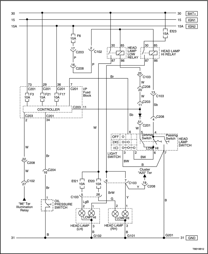
| Step | Action | Value(s) | Yes | No |
| 1 |
Check fuses Ef20, Ef21, Ef23 and F6.
Are any fuses blown?
|
-
|
Go to Step 2
|
Go to Step 4
|
| 2 |
Is the repair complete?
|
-
|
Go to Step 3
|
-
|
| 3 |
Turn the low beam headlamps on.
Does the low beam headlamps work?
|
-
|
Go to Step 6
|
Go to Step 4
|
| 4 |
Check the low beam headlamps system. Refer to the "Low Beam Headlamps Are Inoperative, High Beam Headlamps As Ok"
in this section.
Is any problem found?
|
-
|
Go to Step 5
|
-
|
| 5 |
Repair the problem.
Is the repair complete?
|
-
|
Go to Step 6
|
-
|
| 6 |
Turn the high beam headlamps on.
Do the high beam headlamps work?
|
-
|
System OK
|
Go to Step 7
|
| 7 |
Check the high beam headlamps system. Refer to the "High Beam Headlamps Are Inoperative, Low Beam Headlamps Are Ok"
in this section.
Is any problem found?
|
-
|
Go to Step 8
|
-
|
| 8 |
Repair the problem.
Is the repair complete?
|
-
|
System OK
|
-
|
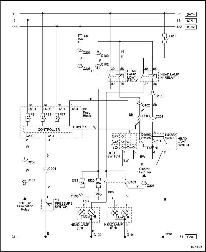
| Step | Action | Value(s) | Yes | No |
| 1 |
Turn the headlamps ON with the headlamp switch.
Do the headlamps work?
|
-
|
Go to Step 3
|
Go to Step 2
|
| 2 |
Repair the regular headlamp system before completing this diagnostic table.
Does the DRL system work after the headlamps have been repaired?
|
-
|
System OK
|
Go to Step 3
|
| 3 |
Check fuse Ef23, F21.
Is fuse Ef23, F21 blown?
|
-
|
Go to Step 4
|
Go to Step 5
|
| 4 |
Is the repair complete?
|
-
|
System OK
|
-
|
| 5 |
Does the voltage equal the specified value?
|
11-14 v
|
Go to Step 7
|
Go to Step 6
|
| 6 |
Repair the power supply circuit for fuse Ef23, F21.
Is the repair complete?
|
-
|
System OK
|
-
|
| 7 |
Is the voltage equal to the specified value?
|
11-14 v
|
Go to Step 9
|
Go to Step 8
|
| 8 |
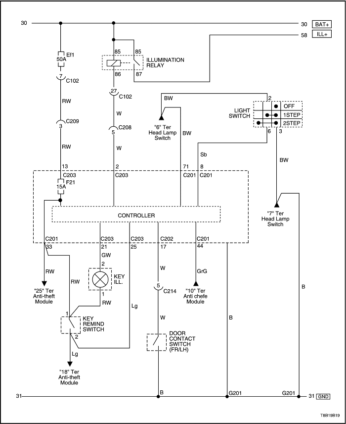
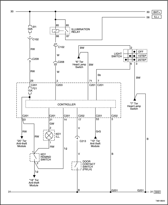
Repair the open circuit fuse Ef23, F21 and terminal 13 of the C203 (29 of the C201 in Hatchback) connector.
Is the repair complete?
|
-
|
System OK
|
-
|
| 9 |
Is the parking brake indicator lamp ON?
|
-
|
Go to Step 10
|
Go to Step 13
|
| 10 |
Disconnect the electrical connector to the parking brake lever switch.
Is the parking brake indicator lamp still ON?
|
-
|
Go to Step 11
|
Go to Step 12
|
| 11 |
Repair the short to ground in the parking brake circuit.
Is the repair complete?
|
-
|
System OK
|
-
|
| 12 |
Replace the parking brake lever switch.
Is the repair complete?
|
-
|
System OK
|
-
|
| 13 |
Is the voltage equal to the specified value?
|
0 v
|
Go to Step 15
|
Go to Step 14
|
| 14 |
Repair the open between fuse F3 and terminal 73 of the C201 connector.
Is the repair complete?
|
-
|
System OK
|
-
|
| 15 |
Replace the controller module (SJB).
Is the repair complete?
|
-
|
System OK
|
-
|
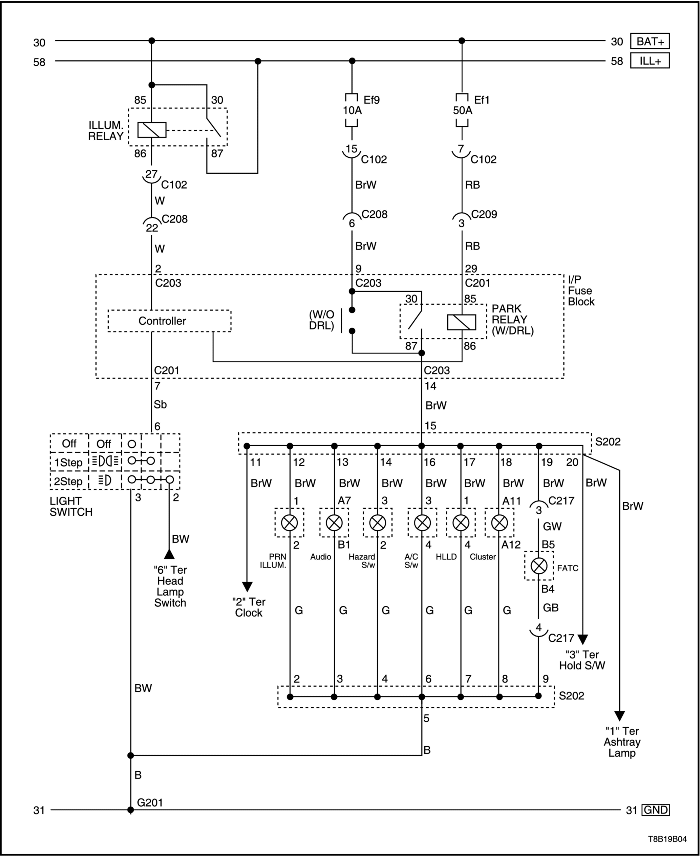
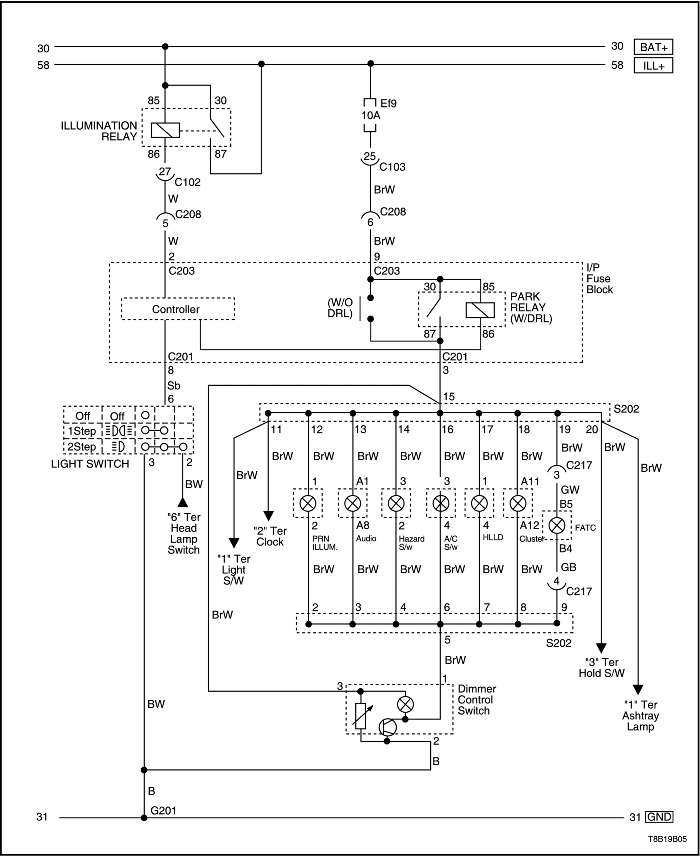
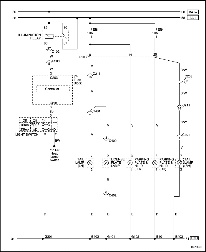
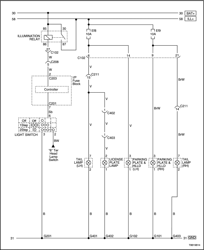
| Step | Action | Value(s) | Yes | No |
| 1 |
Check the headlamps.
Do the headlamps work?
|
-
|
Go to Step 3
|
Go to Step 2
|
| 2 |
Repair the headlamps before continuing with this chart.
After the headlamps have been repaired, are the parking lamps and taillamps still inoperative?
|
-
|
Go to Step 3
|
System OK
|
| 3 |
Does voltage at the bulb socket equal the specified value?
|
11-14 v
|
Go to Step 4
|
Go to Step 7
|
| 4 |
Connect an ohmmeter between ground and the lamp socket negative terminal.
Is the resistance equal to the specified value?
|
≈ 0 Ω
|
Go to Step 6
|
Go to Step 5
|
| 5 |
Repair the ground circuit for the lamps.
Is the repair complete?
|
-
|
System OK
|
-
|
| 6 |
Replace the faulty bulbs.
Is the repair complete?
|
-
|
System OK
|
-
|
| 7 |
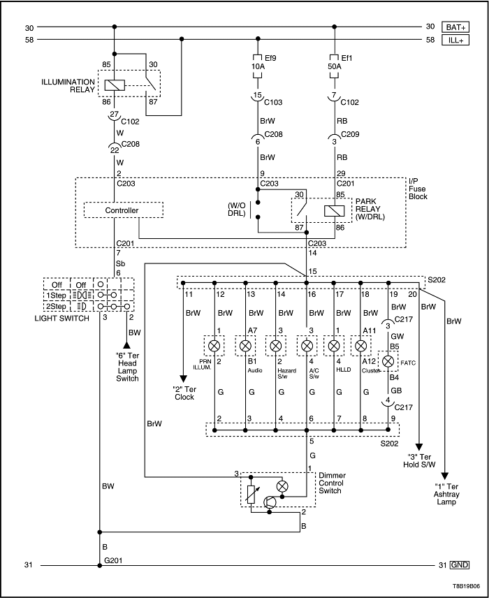
Check fuses Ef8 and Ef9.
Are any of the fuses blown?
|
-
|
Go to Step 8
|
Go to Step 9
|
| 8 |
Is the repair complete?
|
-
|
System OK
|
-
|
| 9 |
Does the voltage at the fuses equal the specified value?
|
11-14 v
|
Go to Step 10
|
-
|
| 10 |
Repair the open circuit between the fuses Ef8 and Ef9 and the illumination lamps.
Is the repair complete?
|
-
|
System OK
|
-
|
| Step | Action | Value(s) | Yes | No |
| 1 |
Check fuse F7.
Is fuse F7 blown?
|
-
|
Go to Step 2
|
Go to Step 3
|
| 2 |
Is the repair complete?
|
-
|
System OK
|
-
|
| 3 |
Use a voltmeter to check the voltage at fuse F7.
Is the voltage at F7 equal to the specified value?
|
11-14 v
|
Go to Step 5
|
Go to Step 4
|
| 4 |
Repair the power supply circuit for fuse F7.
Is the repair complete?
|
-
|
System OK
|
-
|
| 5 |
Does the test lamp illuminate?
|
-
|
Go to Step 6
|
Go to Step 8
|
| 6 |
Connect an ohmmeter between ground and the stoplamp ground terminal.
Is the resistance equal to the specified value?
|
0 Ω
|
Go to Step 8
|
Go to Step 7
|
| 7 |
Repair the ground circuit.
Is the repair complete?
|
-
|
System OK
|
-
|
| 8 |
Is the resistance equal to the specified value?
|
0 Ω
|
Go to Step 10
|
Go to Step 9
|
| 9 |
Replace the stoplamp switch.
Is the repair complete?
|
-
|
System OK
|
-
|
| 10 |
Does the voltmeter show the specified value?
|
11-14 v
|
Go to Step 12
|
Go to Step 11
|
| 11 |
Repair the open circuit between the fuse F7 and the brake switch.
Is the repair complete?
|
-
|
System OK
|
-
|
| 12 |
Repair the open circuit between the brake switch and the stoplamps.
Is the repair complete?
|
-
|
System OK
|
-
|
| Step | Action | Value(s) | Yes | No |
| 1 |
Are the taillamps on?
|
-
|
Go to Step 3
|
Go to Step 2
|
| 2 |
Repair the taillamps before completing this diagnostic table.
Does the CHMSL work after the taillamps are repaired?
|
-
|
System OK
|
Go to Step 3
|
| 3 |
Is the lamp bulb defective?
|
-
|
Go to Step 4
|
Go to Step 5
|
| 4 |
Replace the CHMSL bulb.
Is the repair complete?
|
-
|
System OK
|
-
|
| 5 |
Is the resistance equal to the specified value?
|
≈ 0 Ω
|
Go to Step 7
|
Go to Step 6
|
| 6 |
Repair the open circuit between ground and the BLK wire in the CHMSL connector.
Is the repair complete?
|
-
|
System OK
|
-
|
| 7 |
Repair the open circuit between the brake switch and the CHMSL.
Is the repair complete?
|
-
|
System OK
|
-
|
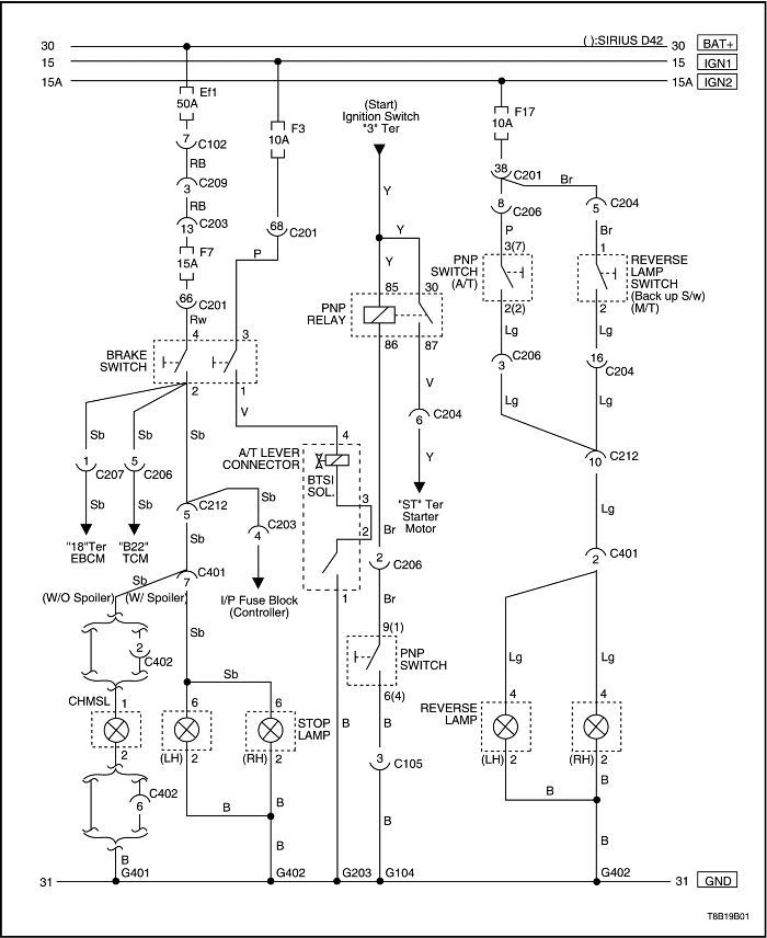
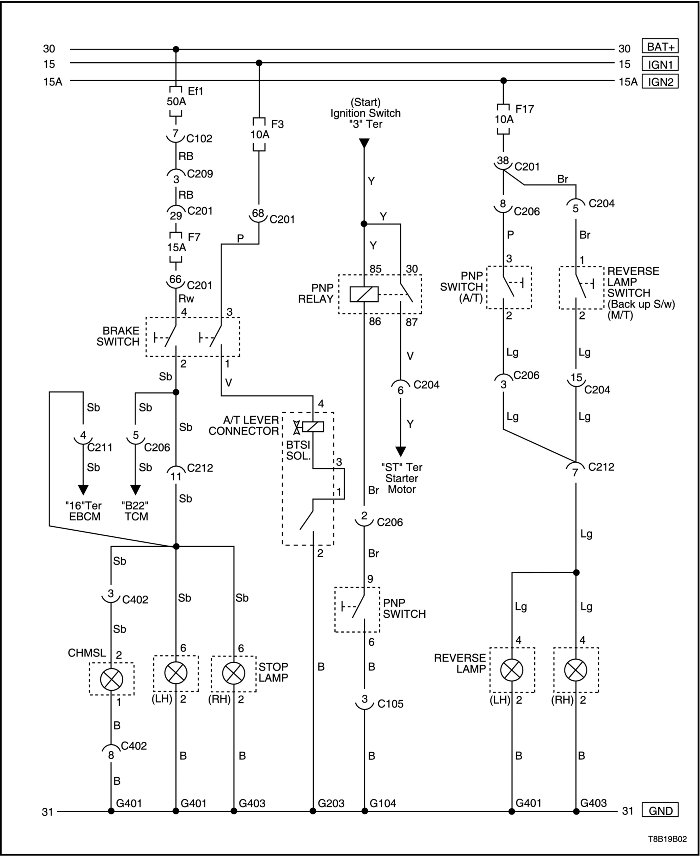
| Step | Action | Value(s) | Yes | No |
| 1 |
Does the battery voltage available at the backup lamp socket positive terminal equal the specified value?
|
11-14 v
|
Go to Step 3
|
Go to Step 2
|
| 2 |
Repair the open circuit between fuse F17 and the backup lamps.
Is the repair complete?
|
-
|
System OK
|
-
|
| 3 |
Connect an ohmmeter between ground and the negative terminal at the bulb socket.
Is the resistance equal to the specified value?
|
0 Ω
|
Go to Step 4
|
Go to Step 5
|
| 4 |
Replace the faulty backup lamps.
Is the repair complete?
|
-
|
System OK
|
-
|
| 5 |
Does the battery voltage available at terminal 1 (or terminal 3(7), if equipped with A/T) equal the specified value?
|
11-14 v
|
Go to Step 7
|
Go to Step 6
|
| 6 |
Repair the open circuit between the backup lamps and the, reverse switch (or the neutral safety/backup switch if equipped with A/T).
Is the repair complete?
|
-
|
System OK
|
-
|
| 7 |
Does the continuity between terminals 1 and 2 (terminals 3(7) and 2(2), if equipped with A/T) equal the specified value?
|
0 Ω
|
Go to Step 9
|
Go to Step 8
|
| 8 |
Replace the reverse switch (neutral safety/backup switch, if equipped with A/T).
Is the repair complete?
|
-
|
System OK
|
-
|
| 9 |
Repair the ground circuit between the reverse switch (neutral safety/backup switch, if equipped with A/T) and ground G402 (G403 in Hatchback).
Is the repair complete?
|
-
|
System OK
|
-
|
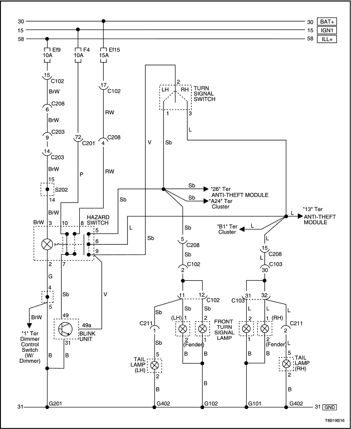
| Step | Action | Value(s) | Yes | No |
| 1 |
Check fuses Ef15 and F4.
Is either fuse blown?
|
-
|
Go to Step 2
|
Go to Step 3
|
| 2 |
Is the repair complete?
|
-
|
System OK
|
-
|
| 3 |
Does the battery voltage available at both fuses Ef15 and F4 equal the specified value?
|
11-14 v
|
Go to Step 4
|
Go to Step 7
|
| 4 |
Does the battery voltage pulsing at the turn signal hazard lamp socket positive terminal equal the specified value?
|
11-14 v
|
Go to Step 5
|
Go to Step 9
|
| 5 |
At each bulb socket, use an ohmmeter to check the ground circuit.
Is the resistance equal to the specified value?
|
≈ 0 Ω
|
Go to Step 6
|
Go to Step 8
|
| 6 |
Replace any faulty turn signal/hazard bulbs.
Is the repair complete?
|
-
|
System OK
|
-
|
| 7 |
Repair the power supply circuit to fuses.
Is the repair complete?
|
-
|
System OK
|
-
|
| 8 |
Repair the open ground wires.
Is the repair complete?
|
-
|
System OK
|
-
|
| 9 |
Does the battery voltage pulsing at the blinker unit terminal 49a equal the specified value?
|
11-14 v
|
Go to Step 15
|
Go to Step 10
|
| 10 |
Does the battery voltage available at the blinker unit terminal 49 equal the specified value?
|
11-14 v
|
Go to Step 11
|
Go to Step 14
|
| 11 |
Is the resistance equal to the specified value?
|
≈ 0 Ω
|
Go to Step 13
|
Go to Step 12
|
| 12 |
Repair the blinker unit ground connection.
Is the repair complete?
|
-
|
System OK
|
-
|
| 13 |
Replace the faulty blinker unit.
Is the repair complete?
|
-
|
System OK
|
-
|
| 14 |
Does the battery voltage available at both terminals equal the specified value?
|
11-14 v
|
Go to Step 15
|
Go to Step 20
|
| 15 |
Do both tests show the specified value?
|
0 Ω
|
Go to Step 18
|
Go to Step 17
|
| 16 |
Does the continuity between terminals 5, 6, and 9 equal the specified value?
|
0 Ω
|
Go to Step 19
|
Go to Step 17
|
| 17 |
Replace the faulty hazard lamp switch.
Is the repair complete?
|
-
|
System OK
|
-
|
| 18 |
Repair the open circuit between the hazard lamp switch terminal 7 and the blinker unit terminal 49.
Is the repair complete?
|
-
|
System OK
|
-
|
| 19 |
Repair the open circuit between the hazard lamp switch and the fuses Ef15 or F4.
Is the repair complete?
|
-
|
System OK
|
-
|
| Step | Action | Value(s) | Yes | No |
| 1 |
Check fuse Ef15.
Is fuse Ef15 blown?
|
-
|
Go to Step 2
|
Go to Step 3
|
| 2 |
Is the repair complete?
|
-
|
System OK
|
-
|
| 3 |
Use a voltmeter to check for power to fuse Ef15.
Does the battery voltage available at fuse Ef15 equal the value specified?
|
11-14 v
|
Go to Step 5
|
Go to Step 4
|
| 4 |
Repair the power supply circuit to fuse Ef15.
Is the repair complete?
|
-
|
System OK
|
-
|
| 5 |
Does the battery voltage available at connector terminal 8 equal the value specified?
|
11-14 v
|
Go to Step 6
|
Go to Step 9
|
| 6 |
Is the resistance equal to the specified value?
|
0 Ω
|
Go to Step 7
|
Go to Step 10
|
| 7 |
Is the resistance equal to the specified value?
|
0 Ω
|
Go to Step 8
|
Go to Step 9
|
| 8 |
Repair the open circuit between the hazard switch connector terminal 8 and fuse Ef15.
Is the repair complete?
|
-
|
System OK
|
-
|
| 9 |
Replace the faulty hazard switch.
Is the repair complete?
|
-
|
System OK
|
-
|
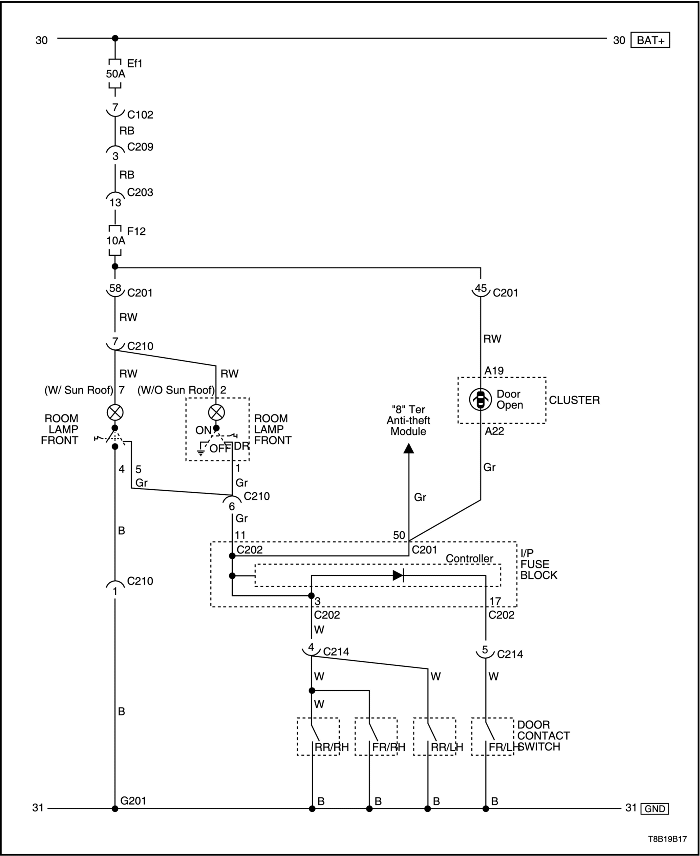
| Step | Action | Value(s) | Yes | No |
| 1 |
Does the bulb pass the visual and physical checks?
|
-
|
Go to Step 3
|
Go to Step 2
|
| 2 |
Replace the bulb.
Is the repair complete?
|
-
|
System OK
|
-
|
| 3 |
Is fuse Ef1, F12 blown?
|
-
|
Go to Step 4
|
Go to Step 5
|
| 4 |
Is the repair complete?
|
-
|
System OK
|
-
|
| 5 |
Check fuse Ef1, F12.
Does the voltage at fuse Ef1, F12 equal the specified value?
|
11-14 v
|
Go to Step 7
|
Go to Step 6
|
| 6 |
Repair the open power supply circuit for fuse Ef1, F12.
Is the repair complete?
|
-
|
System OK
|
-
|
| 7 |
Does the voltage at connector terminal 2 (7; W/ Sunroof) equal the value specified?
|
11-14 v
|
Go to Step 8
|
Go to Step 9
|
| 8 |
Repair the open circuit between fuse Ef1, F12 and the interior courtesy lamp terminal 2 (7; W/ Sunroof).
Is the repair complete?
|
-
|
System OK
|
-
|
| 9 |
Is the resistance equal to the specified value?
|
0Ω
|
Go to Step 10
|
Go to Step 11
|
| 10 |
Replace the interior courtesy lamp switch assembly.
Is the repair complete?
|
-
|
System OK
|
-
|
| 11 |
Repair the ground circuit for the interior courtesy lamp.
Is the repair complete?
|
-
|
System OK
|
-
|
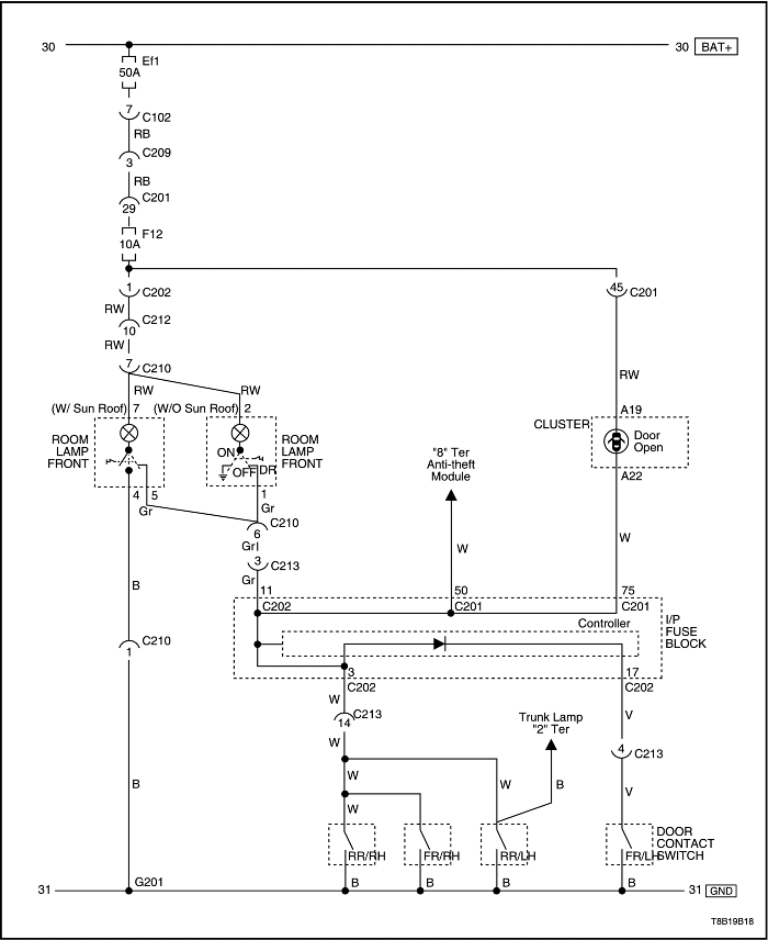
| Step | Action | Value(s) | Yes | No |
| 1 |
Does the bulb pass the visual and physical check?
|
-
|
Go to Step 3
|
Go to Step 2
|
| 2 |
Replace the bulb.
Is the repair complete?
|
-
|
System OK
|
-
|
| 3 |
Is fuse EF22 blown?
|
-
|
Go to Step 4
|
Go to Step 5
|
| 4 |
Is the repair complete?
|
-
|
System OK
|
-
|
| 5 |
Check fuse EF22.
Does the voltage at fuse EF22 equal the specified value?
|
11-14 v
|
Go to Step 7
|
Go to Step 6
|
| 6 |
Repair the open power supply circuit for fuse EF22.
Is the repair complete?
|
-
|
System OK
|
-
|
| 7 |
Does the voltage at the BRN wire equal the specified value?
|
11-14 v
|
Go to Step 8
|
Go to Step 9
|
| 8 |
Repair the open circuit between fuse EF22 and the luggage compartment lamp.
Is the repair complete?
|
-
|
System OK
|
-
|
| 9 |
Does the voltage at the luggage compartment lamp switch equal the specified value?
|
11-14 v
|
Go to Step 11
|
Go to Step 10
|
| 10 |
Repair the open circuit between the luggage compartment lamp and the luggage compartment lamp switch.
Is the repair complete?
|
-
|
System OK
|
-
|
| 11 |
Use an ohmmeter to check the resistance between ground and the BLK wire at the luggage compartment lamp switch connector (harness side).
Is the resistance equal to the specified value?
|
0Ω
|
Go to Step 12
|
Go to Step 13
|
| 12 |
Replace the luggage compartment lamp switch.
Is the repair complete?
|
-
|
System OK
|
-
|
| 13 |
Repair the ground circuit for the interior courtesy lamp.
Is the repair complete?
|
-
|
System OK
|
-
|
| Step | Action | Value(s) | Yes | No |
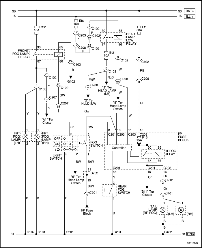
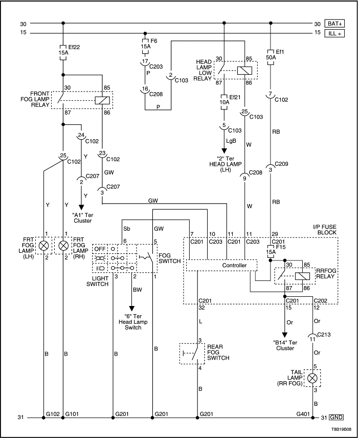
| 1 |
Check fuse Ef22.
Is fuse Ef22 blown?
|
-
|
Go to Step 2
|
Go to Step 3
|
| 2 |
Is the repair complete?
|
-
|
System OK
|
-
|
| 3 |
Use a voltmeter to check fuse Ef22.
Does the battery voltage available at fuse Ef22 equal the specified value?
|
11-14 v
|
Go to Step 5
|
Go to Step 4
|
| 4 |
Repair the open circuit from the battery to fuse Ef22.
Is the repair complete?
|
-
|
System OK
|
-
|
| 5 |
Remove the fog lamp relay and temporarily substitute a known good relay, such as the headlamp relay. (Do not substitute the illumination lamp relay.)
Do the fog lamps work with the substituted relay?
|
-
|
Go to Step 6
|
Go to Step 7
|
| 6 |
Is the repair complete?
|
-
|
System OK
|
-
|
| 7 |
Does the voltage available at the fog lamp relay socket equal the specified value?
|
11-14 v
|
Go to Step 9
|
Go to Step 8
|
| 8 |
Repair the open circuit between fuse Ef22 and the fog lamp relay.
Is the repair complete?
|
-
|
System OK
|
-
|
| 9 |
At the fog lamp relay socket, use an ohmmeter to verify that the connector for relay terminal 86 is connected to ground.
Does the resistance equal the specified value?
|
0 Ω
|
Go to Step 11
|
Go to Step 10
|
| 10 |
Repair the ground circuit for the fog lamp relay.
Is the repair complete?
|
-
|
System OK
|
-
|
| 11 |
Does the battery voltage available at terminal 1 of the fog lamp connector equal the specified value?
|
11-14 v
|
Go to Step 13
|
Go to Step 12
|
| 12 |
Repair the open circuit between the fog lamp relay terminal 87 and the fog lamps.
Is the repair complete?
|
-
|
System OK
|
-
|
| 13 |
Use an ohmmeter (or test lamp) to check the ground at terminal 2 of the fog lamp connector.
Does the resistance equal the specified value?
|
0 Ω
|
Go to Step 15
|
Go to Step 14
|
| 14 |
Repair the fog lamp ground circuit.
Is the repair complete?
|
-
|
System OK
|
-
|
| 15 |
Replace the faulty fog lamp bulbs.
Is the repair complete?
|
-
|
System OK
|
-
|
| © Copyright Chevrolet Europe. All rights reserved |


