MAINTENANCE AND REPAIR
ON-VEHICLE SERVICE
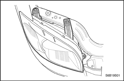


Headlamps
Removal Procedure
- Remove the radiator grille.
- Remove the headlamp mounting bolts.
- Disconnect the electrical connectors.
- Remove the headlamp assembly.
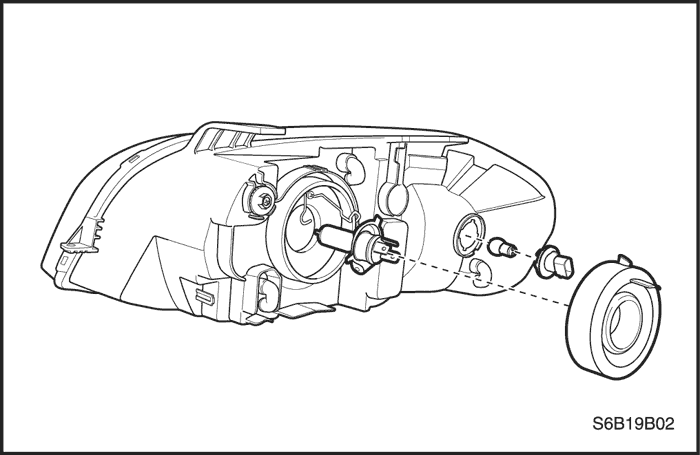
- Remove the cap concealing the headlamp bulb.
- Disconnect the headlamp bulb electrical connector.
- Remove the retaining wire.
- Remove the headlamp bulb.
Installation Procedure
- Install the headlamp bulb.
- Install the retaining wire.
- Connect the headlamp bulb electrical connector.
- Install the cap concealing the headlamp bulb.
- Connect the electrical connectors.
Notice : Dissimilar metals in direct contact with each other may corrode rapidly. Make sure to use the correct fasteners to prevent premature corrosion.
- Install the headlamp assembly with the bolts.
Tighten
Tighten the headlamp assembly bolts to 4 N•m (35 lb-in).
- Install the radiator grille.
Turn Signal Lamps
Removal Procedure
- Disconnect the negative battery cable.
- Remove the headlamp. Refer to "Headlamps"
in this section.
- Remove the turn signel lamp bulb.
Installation Procedure
- Install the turn signal lamp bulb.
- Install the headlamp. Refer to "Headlamps"
in this section.
- Connect the negative battery cable.
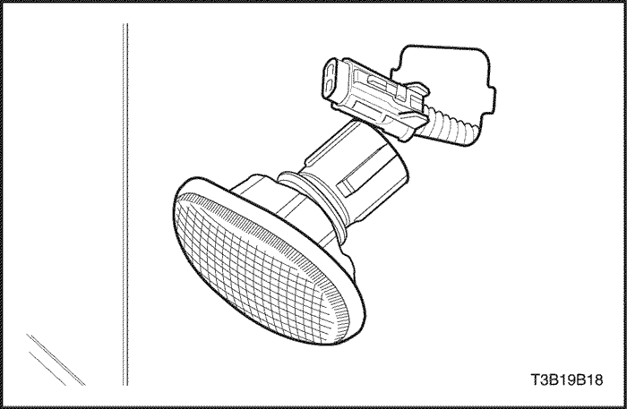
Side Turn Signal Lamps
Removal Procedure
- Disconnect the negative battery cable.
- Slide the side turn signal lamp rearward.
- Remove the lamp.
- Disconnect the electrical connector.
Installation Procedure
- Connect the electrical connector.
- Install the side turn signal lamp.
- Connect the negative battery cable.
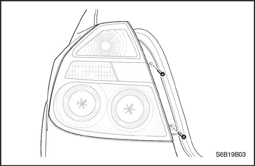
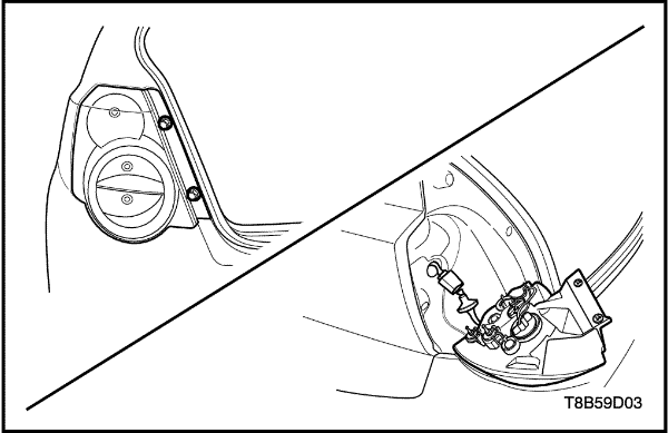
Tail Lamps
Removal Procedure
- Remove the luggage compartment rear quarter trim panel.
- Disconnect the electrical connectors.
- Remove the screws and the lamp assembly.
- Remove the bulb(s).
Installation Procedure
- Install the bulb(s).
Notice : Dissimilar metals in direct contact with each other may corrode rapidly. Make sure to use the correct fasteners to prevent premature corrosion.
- Install the lamp assembly with the screws.
Tighten
Tighten the taillamp assembly nuts to 3 N•m (27 lb-in).
- Connect the electrical connectors.
- Install the luggage compartment rear quarter trim panel.
Tail Lamps (Hatchback)
Removal Procedure
- Disconnect the negative battery cable.
- Remove the screws and the lamps assembly.
- Remove the bulb(s).
Installation Procedure
- Install the bulb(s).
- Install the lamp assembly with the screws.
Tighten
Tighten the tail lamp assembly screws to 3 N•m (27 lb-in).
- Connect the negative battery cable.
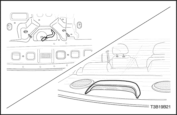
Center High-Mounted Stop Lamp
Removal Procedure
- Disconnect the negative battery cable.
- Open the rear deck lid.
- Remove the screws and the CHMSL.
- Remove the center high-mounted stoplamp (CHMSL) bulb.
Installation Procedure
Notice : Dissimilar metals in direct contact with each other may corrode rapidly. Make sure to use the correct fasteners to prevent premature corrosion.
- Install the CHMSL bulb.
- Install the CHMSL with the screws.
- Connect the negative battery cable.
Center High-Mounted Stop Lamp (Attached Spoiler)
Removal Procedure
- Disconnect the negative battery cable.
- Remove the spoiler. Refer to Section 9M, Exterior Trim.
- Remove the nuts and spoiler.
- Remove the screws and the center high-mounted stoplamp (CHMSL).
Installation Procedure
Notice : Dissimilar metals in direct contact with each other may corrode rapidly. Make sure to use the correct fasteners to prevent premature corrosion.
- Connect the electrical connector.
- Install the CHMSL with the screws.
Tighten
Tighten the CHMSL mounting screws to 3 N•m (27 lb-in).
- Install the spoiler. Refer to Section 9M, Exterior Trim.
- Connect the negative battery cable.
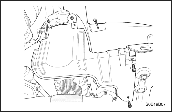
Fog Lamps
Removal Procedure
- Disconnect the negative battery cable.
- Remove the nuts and the engine under cover.
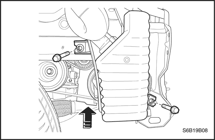
- Remove the bolts and decline the resonator. Refer to Section 1C, Engine Mechanical.
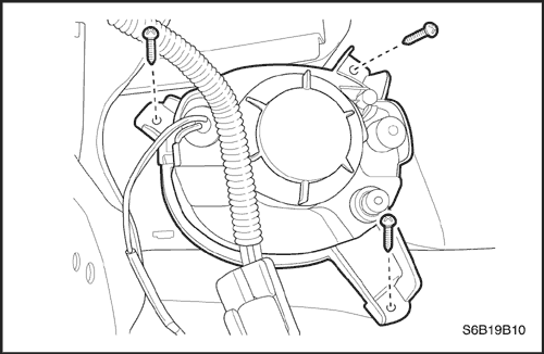
- Remove the nuts securing the fog lamp assembly.
- Remove the fog lamp assembly.
- Disconnect the electrical connector.
Installation Procedure
- Install the bulb.
- Connect the electrical connector.
- Install the fog lamp assembly.
Notice : Dissimilar metals in direct contact with each other may corrode rapidly. Make sure to use the correct fasteners to prevent premature corrosion.
- Secure the fog lamp assembly with the screw.
Tighten
Tighten the fog lamp assembly screws to 5 N•m (44 lb-in).
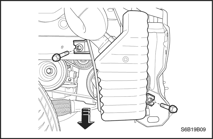
- Install the resonator with the bolts.
- Install the engine under cover with the screw.
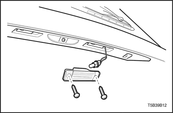
License Plate Lamp
Removal Procedure
- Remove the screws.
- Disconnect the electrical connector.
- Remove the lamp assembly.
- Remove the bulb.
Installation Procedure
- Install a new bulb.
- Connect the electrical connector.
Notice : Dissimilar metals in direct contact with each other may corrode rapidly. Make sure to use the correct fasteners to prevent premature corrosion.
- Install the lamp assembly with the screws.
Tighten
Tighten the license plate lamp screws to 1.5 N•m (13 lb-in).
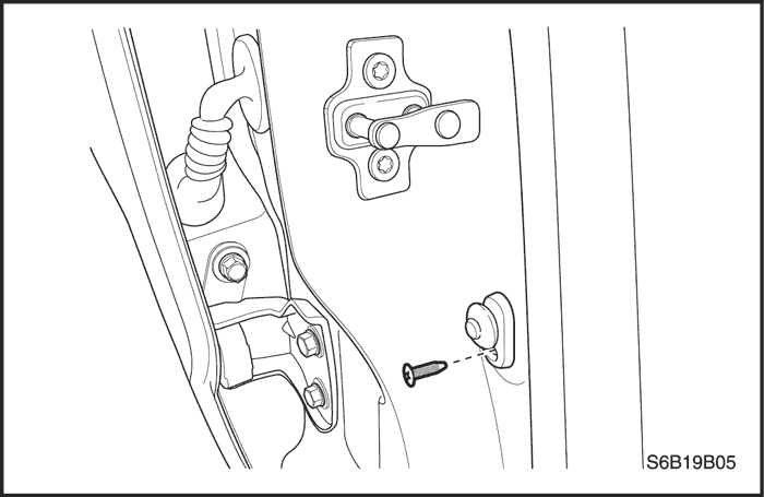
Door Jamb Switch
Removal Procedure
- Remove the screw and the door jamb switch.
- Disconnect the electrical connector.
Installation Procedure
- Connect the electrical connector.
Notice : Dissimilar metals in direct contact with each other may corrode rapidly. Make sure to use the correct fasteners to prevent premature corrosion.
- Install the door jamb switch with the screw.
Tighten
Tighten the door jamb switch screw to 4.5 N•m (40 lb-in).
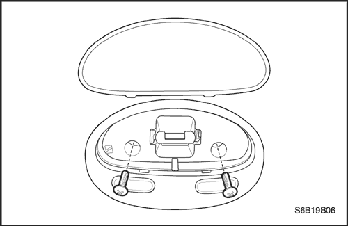
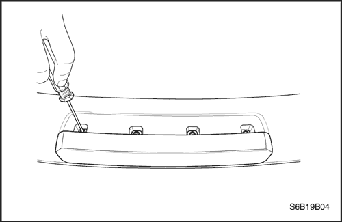
Interior Courtesy Lamp
Removal Procedure
- Disconnect the negative battery cable.
- Pry off the interior courtesy lamp lens by inserting a screwdriver into the recess along the edge of the lens.
- Remove the screws and the interior courtesy lamp housing from the headliner.
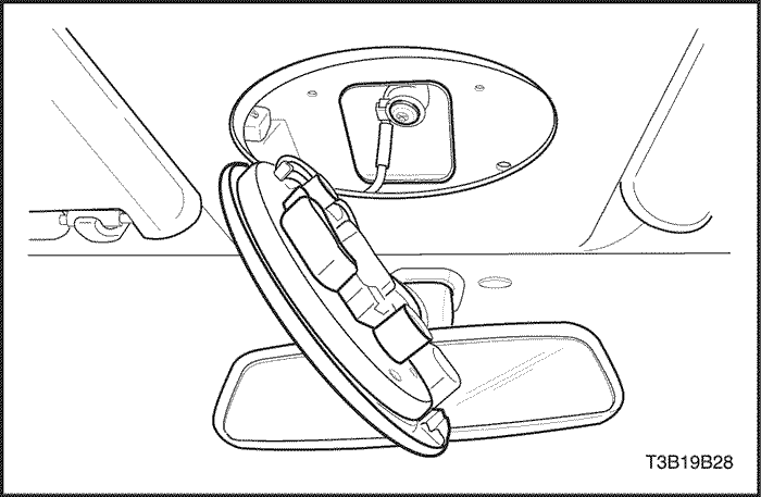
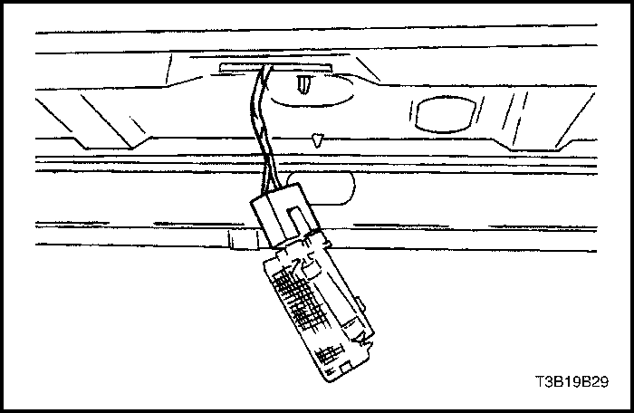
- Disconnect the electrical connector.
- Remove the bulb.
Installation Procedure
- Install a new bulb.
- Connect the electrical connector.
Notice : Dissimilar metals in direct contact with each other may corrode rapidly. Make sure to use the correct fasteners to prevent premature corrosion.
- Install the interior courtesy lamp housing to the headliner with the screws.
Tighten
Tighten the interior courtesy lamp housing screws to 2.5 N•m (22 lb-in).
- Press the courtesy lamp lens onto the housing.
- Connect the negative battery cable.
Luggage Compartment Lamp
Removal Procedure
- Disconnect the negative battery cable.
- Gently pry the luggage compartment lamp off by inserting a flathead screwdriver into the recess on the edge of the lamp.
- Disconnect the electrical connector.
- Remove the bulb.
Installation Procedure
- Install a new bulb.
- Connect the electrical connector.
- Insert the luggage compartment lamp into the recess and press the lens into place.
- Connect the negative battery cable.
| © Copyright Chevrolet Europe. All rights reserved |


