Aveo |
||||||||
|
||||||||
|
Application
|
N•m
|
Lb-Ft
|
Lb-In
|
|
Air Deflector Screws
|
2
|
-
|
18
|
|
Clock Screws
|
3
|
-
|
27
|
|
Driver Knee Bolster Bolts
|
10
|
-
|
89
|
|
Floor Console Brace Bolts
|
4
|
-
|
35
|
|
Floor Console Brace Nuts
|
4
|
-
|
35
|
|
HVAC Controls Screws
|
4
|
-
|
35
|
|
Instrument Cluster Screws
|
4
|
-
|
35
|
|
Instrument Cluster Trim Panel Screws
|
4
|
-
|
35
|
|
Instrument Panel End Bolts
|
20
|
15
|
-
|
|
Instrument Panel End Screws
|
4
|
-
|
35
|
|
Instrument Panel Nuts Above the Steering Column
|
20
|
15
|
-
|
|
Instrument Panel Bolts Behind the HVAC Controls
|
4
|
-
|
35
|
|
Steering Column Bracket Nut
|
22
|
16
|
-
|
|
Steering Column Lower Trim Cover Screws
|
2.5
|
-
|
22
|
|
Steering Column U-Clamp Nuts
|
22
|
16
|
-
|
|
Steering Column Upper Trim Cover Screws
|
3
|
-
|
27
|
|
Indicator Lamp
|
Color
|
Bulb
|
|
ABS Warning
|
Amber
|
14 v 1.4 W
|
|
Airbag Warning
|
Red
|
14 v 1.4 W
|
|
Battery Charge Indicator
|
Red
|
14 v 1.4 W
|
|
Check Engine
|
Amber
|
14 v 1.4 W
|
|
Door Open Warning
|
Red
|
14 v 1.4 W
|
|
Engine Overheat
|
Red
|
14 v 1.4 W
|
|
Fasten Seat Belt Warning
|
Red
|
14 v 1.4 W
|
|
High Beam Indicator
|
Blue
|
14 v 1.4 W
|
|
Low Fuel Level Warning
|
Amber
|
14 v 1.4 W
|
|
Oil Pressure Warning
|
Red
|
14 v 1.4 W
|
|
Parking Brake Indicator and Brake Fluid Warning
|
Red
|
14 v 1.4 W
|
|
Service Engine Soon Warning
|
Amber
|
14 v 1.4 W
|
|
Transaxle Power Mode Indicator
|
Amber
|
14 v 1.4 W
|
|
Turn Signal Indicators
|
Green
|
14 v 1.4 W
|
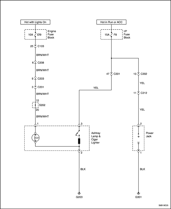
| Step | Action | Value(s) | Yes | No |
| 1 |
Check fuse F8.
Is the fuse blown?
|
-
|
Go to Step 2
|
Go to Step 3
|
| 2 |
Is the repair complete?
|
-
|
System OK
|
-
|
| 3 |
Does the battery voltage available at the fuse F8 match the value specified?
|
11-14 v
|
Go to Step 5
|
Go to Step 4
|
| 4 |
Repair the open power supply circuit for fuse F8.
Is the repair complete?
|
-
|
System OK
|
-
|
| 5 |
Does the battery voltage available at the YEL wire match the value specified?
|
11-14 v
|
Go to Step 7
|
Go to Step 6
|
| 6 |
Repair the open circuit between fuse F8 and the cigar lighter.
Is the repair complete?
|
-
|
System OK
|
-
|
| 7 |
With the ignition key still in the ACC position, connect the voltmeter between the YEL and the BLK wires at the cigar lighter connector.
Does the battery voltage match the value specified?
|
11-14 v
|
Go to Step 9
|
Go to Step 8
|
| 8 |
Repair the open ground circuit.
Is the repair complete?
|
-
|
System OK
|
-
|
| 9 |
Replace the cigar lighter.
Is the repair complete?
|
-
|
System OK
|
-
|
| Step | Action | Value(s) | Yes | No |
| 1 |
Check fuses Ef9, F9, Ef1 and F21.
Is either fuse Ef9, F9, Ef1 and F21 blown?
|
-
|
Go to Step 2
|
Go to Step 3
|
| 2 |
Is the repair complete?
|
-
|
System OK
|
-
|
| 3 |
Does the voltmeter indicate the value specified?
|
11-14 v
|
Go to Step 5
|
Go to Step 4
|
| 4 |
Repair the open power supply circuit for the fuse.
Is the repair complete?
|
-
|
System OK
|
-
|
| 5 |
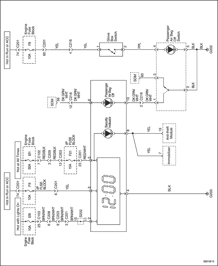
Use a voltmeter to check the battery voltage available at the clock connector terminal 5.
Does the voltmeter indicate the value specified?
|
11-14 v
|
Go to Step 7
|
Go to Step 6
|
| 6 |
Repair the open circuit between the clock connector terminal 5 and the fuse F21.
Is the repair complete?
|
-
|
System OK
|
-
|
| 7 |
Turn the ignition ON.
Is battery voltage available at the clock connector terminal 3?
|
-
|
Go to Step 9
|
Go to Step 8
|
| 8 |
Repair the open circuit between terminal 15 of the clock connector and fuse F9.
Is the repair complete?
|
-
|
System OK
|
-
|
| 9 |
Check continuity between terminal 4 of the clock connector and ground.
Does the multimeter indicate the value specified?
|
0 Ω
|
Go to Step 10
|
Go to Step 11
|
| 10 |
Replace the clock.
Is the repair complete?
|
-
|
System OK
|
-
|
| 11 |
Repair the open ground circuit between terminal 4 the clock connector and ground G203.
Is the repair complete?
|
-
|
System OK
|
-
|
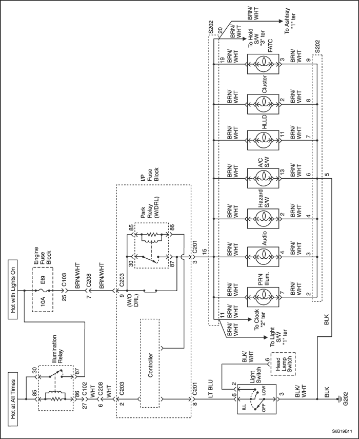
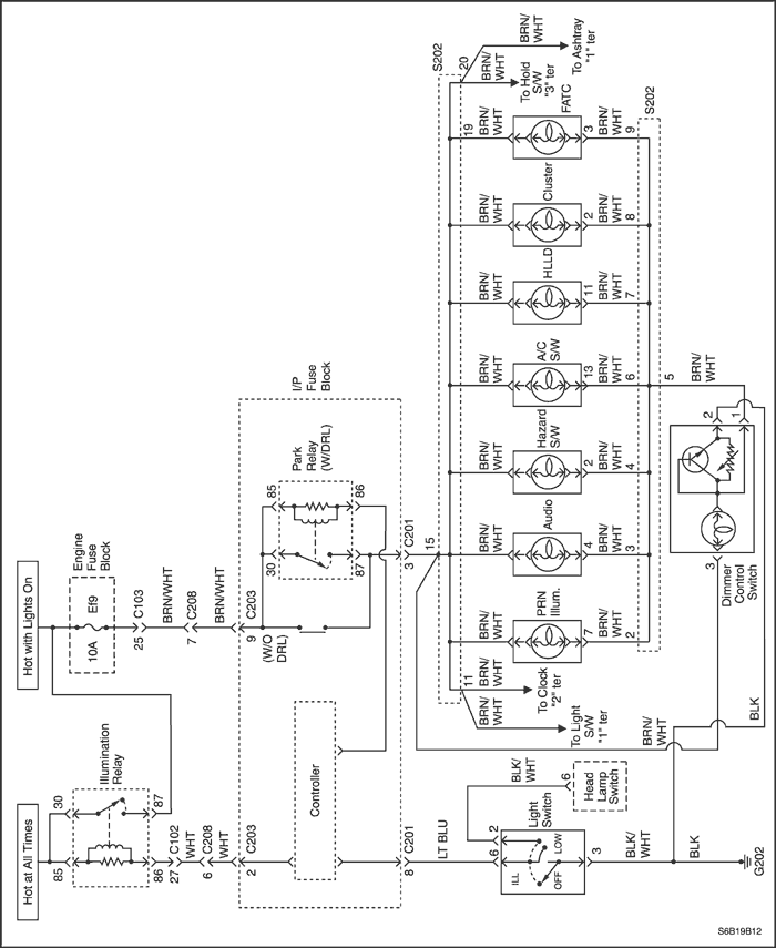
| Step | Action | Value(s) | Yes | No |
| 1 |
Check fuse Ef9.
Is fuse Ef9 blown?
|
-
|
Go to Step 2
|
Go to Step 3
|
| 2 |
Is the repair complete?
|
-
|
System OK
|
-
|
| 3 |
Does the battery voltage match the value specified?
|
11-14 v
|
Go to Step 5
|
Go to Step 4
|
| 4 |
Repair the open power supply circuit to fuse Ef9.
Is the repair complete?
|
-
|
System OK
|
-
|
| 5 |
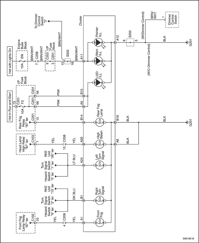
Use an ohmmeter to check the resistance between ground and the BLK wire of the dimmer control switch connector.
Is the resistance equal to the specified value?
|
0
|
Go to Step 7
|
Go to Step 6
|
| 6 |
Repair the open ground circuit.
Is the repair complete?
|
-
|
System OK
|
-
|
| 7 |
Does the battery voltage match the value specified?
|
11-14 v
|
Go to Step 9
|
Go to Step 8
|
| 8 |
Repair the open circuit between the BRN/WHT wire of the dimmer control switch connector and fuse Ef9.
Is the repair complete?
|
-
|
System OK
|
-
|
| 9 |
Does the battery voltage match the value specified?
|
11-14 v
|
Go to Step 11
|
Go to Step 10
|
| 10 |
Repair the open circuit between the BRN/WHT wire of the dimmer control switch connector and each lamps.
Is the repair complete?
|
-
|
System OK
|
-
|
| 11 |
Replace the dimmer control switch.
|
-
|
System OK
|
-
|
| Step | Action | Value(s) | Yes | No |
| 1 |
Check fuse Ef9.
Is fuse Ef9 blown?
|
-
|
Go to Step 2
|
Go to Step 3
|
| 2 |
Is the repair complete?
|
-
|
System OK
|
-
|
| 3 |
Does the battery voltage match the value specified?
|
11-14 v
|
Go to Step 5
|
Go to Step 4
|
| 4 |
Repair the open circuit power supply circuit to fuse Ef9.
Is the repair complete?
|
-
|
System OK
|
-
|
| 5 |
Does the battery voltage match the value specified?
|
11-14 v
|
Go to Step 7
|
Go to Step 6
|
| 6 |
Repair the open circuit between the automatic transaxle position lamp socket and fuse Ef9.
Is the repair complete?
|
-
|
System OK
|
-
|
| 7 |
Is the resistance equal to the value specified?
|
≈ 0 Ω
|
Go to Step 9
|
Go to Step 8
|
| 8 |
Repair the open ground circuit between the automatic transaxle position lamp socket and ground.
Is the repair complete?
|
-
|
System OK
|
-
|
| 9 |
Replace the automatic transaxle position lamp.
Is the repair complete?
|
-
|
System OK
|
-
|
| Step | Action | Value(s) | Yes | No |
| 1 |
Is the vehicle speed sensor DTC set?
|
-
|
Go to Step 2
|
|
| 2 |
Does the ohmmeter indicate the specified value?
|
0 Ω
|
Go to Step 4
|
Go to Step 3
|
| 3 |
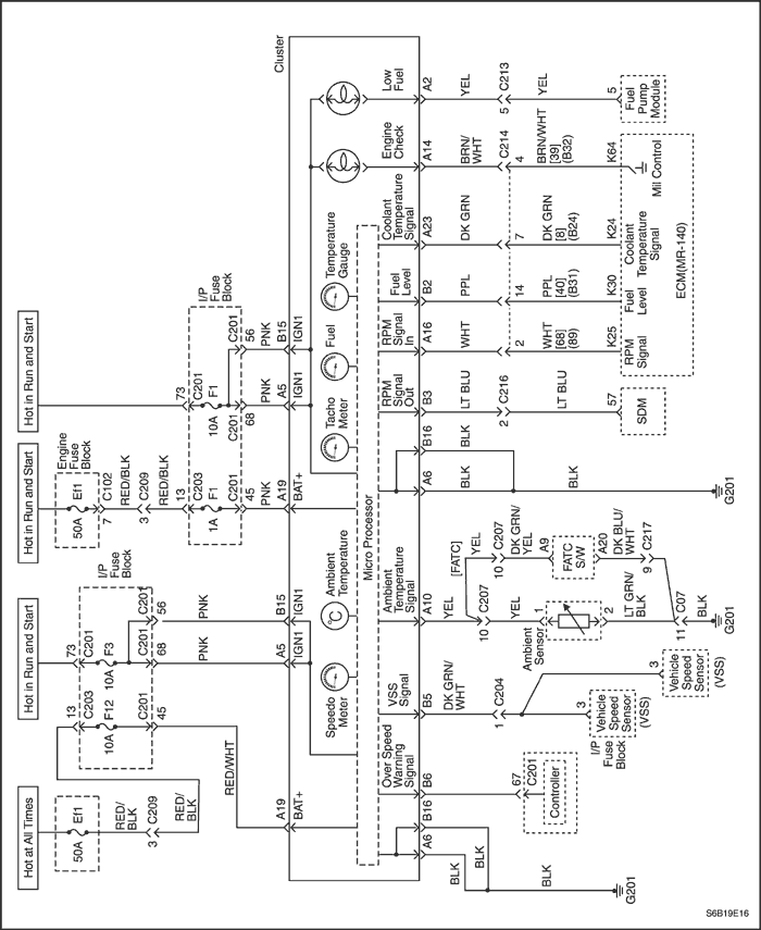
Repair the open circuit between the instrument cluster connector terminal A19 and the ECM terminal K30 (HV Type: B31, Sirius D4: 40).
Is the repair complete?
|
-
|
System OK
|
-
|
| 4 |
Replace the fuel gauge.
Is the repair complete?
|
-
|
System OK
|
-
|
| Step | Action | Value(s) | Yes | No |
| 1 |
Allow the engine to cool to room temperature.
With the ignition ON, does the temperature gauge always read at the high end of the scale?
|
-
|
Go to Step 7
|
Go to Step 2
|
| 2 |
Disconnect ECM electrical connector.
Does the temperature gauge indicator drop to the low end of the scale?
|
-
|
Go to Step 3
|
|
| 3 |
Check for a short to ground between the ECM and the temperature gauge.
Is there a short to ground?
|
-
|
Go to Step 4
|
Go to Step 5
|
| 4 |
Repair the short to ground.
Is the repair complete?
|
-
|
System OK
|
-
|
| 5 |
Replace the temperature gauge.
Is the repair complete?
|
-
|
System OK
|
-
|
| 6 |
Does the voltage equal the value specified?
|
11-14 v
|
Go to Step 9
|
Go to Step 7
|
| 7 |
Check for an open circuit between the ECM and the temperature gauge.
Is there an open circuit?
|
-
|
Go to Step 8
|
Go to Step 5
|
| 8 |
Repair the open circuit between the ECM and the temperature gauge.
Is the repair complete?
|
-
|
System OK
|
-
|
| 9 |
Does the temperature gauge move to the high end of the scale?
|
-
|
Go to Step 5
|
| Step | Action | Value(s) | Yes | No |
| 1 |
Check fuse F1.
Is fuse F1 blown?
|
-
|
Go to Step 2
|
Go to Step 3
|
| 2 |
Is the repair complete?
|
-
|
System OK
|
-
|
| 3 |
Does the battery voltage match the value specified?
|
11-14 v
|
Go to Step 5
|
Go to Step 4
|
| 4 |
Repair the open power supply circuit to fuse F1.
Is the repair complete?
|
-
|
System OK
|
Go to Step 3
|
| 5 |
Does the battery voltage match the value specified?
|
11-14 v
|
Go to Step 7
|
Go to Step 6
|
| 6 |
Repair the open circuit between fuse F1 and the instrument cluster connector A5.
Is the repair complete?
|
-
|
System OK
|
-
|
| 7 |
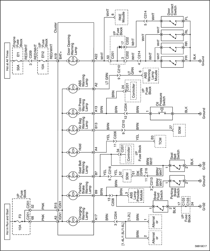
Check the instrument cluster indicator lamp bulbs.
Are the bulbs OK?
|
-
|
Go to Step 9
|
Go to Step 8
|
| 8 |
Is the repair complete?
|
-
|
System OK
|
-
|
| 9 |
Replace the instrument cluster.
Is the repair complete?
|
-
|
System OK
|
-
|
| © Copyright Chevrolet Europe. All rights reserved |


