To the top of the document
Cruze
   
GMDE Start Page Load static TOC Load dynamic TOC Help?

Front Wheel Drive Shaft Inner Joint and Boot Replacement

Special Tools

    • CH-804 Tensioner
    • GE-396 Snap Ring Pliers

For equivalent regional tools, refer to Special Tools .

Removal Procedure


    2027958
  1. Remove the large seal retaining clamp from the CV joint with a side cutter. Discard the seal retaining clamp.
  2. If equipped with a small swage ring, use a hand grinder to cut through the swage ring, taking care not to damage the halfshaft bar, in order to remove the swage ring. Otherwise, remove the small seal retaining clamp with a side cutter. Discard the retaining clamp.
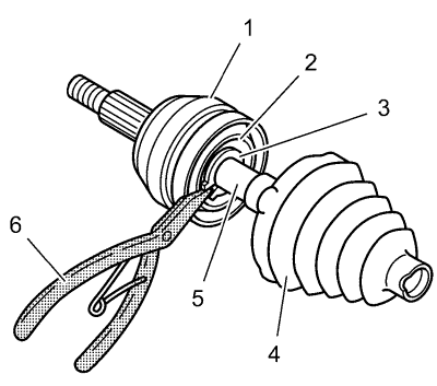
  3. Separate the halfshaft outboard seal from CV joint outer race (1) at large diameter.
  4. Slide the seal (4) away from joint along halfshaft bar (5).
  5. Wipe the grease from the face of the CV joint inner race (2).
  6. Spread the ears on the race retaining ring (3) with GE-396 pliers (6)
  7. Remove the CV joint assembly (1) from the halfshaft bar (4).
  8. Remove the halfshaft outboard seal (4) from the halfshaft bar (5).
  9. Discard the old outboard seal.

  10. 2027963
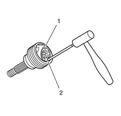
  11. Place a brass drift against the CV joint cage (1).
  12. Tap gently on the brass drift with a hammer in order to tilt the cage (1).
  13. Remove the first chrome alloy ball (2) when the CV joint cage (1) tilts.
  14. Tilt the CV joint cage (1) in the opposite direction to remove the opposing chrome alloy ball (2).
  15. Repeat this process to remove all 6 of the balls.

  16. 2027965
  17. Pivot the CV joint cage (4) and the inner race 90 degrees to the centre line of the outer race (2). At the same time, align the cage windows (3) with the lands of the outer race (1).
  18. Lift out the cage (4) and the inner race.

  19. 2027968
  20. Remove the inner race (1) from the cage (2) by rotating the inner race (1) upward.
  21. Clean the following items thoroughly with cleaning solvent. Remove all traces of old grease and any contaminates.
  22. • The inner and outer race assemblies
    • The CV joint cage
    • The chrome alloy balls
  23. Dry all the parts.
  24. Check the CV joint assembly for the following items:
  25. • Unusual wear
    • Cracks
    • Damage
  26. Replace any damaged parts.
  27. Clean the halfshaft bar. Use a wire brush to remove any rust in the seal mounting area (grooves).

  28. 2028230
  29. If equipped with a damping wight (2) remove retaining clamp from the damping wight.
  30. Remove damping wight (2) from halfshaft bar (1).

  31. 2028232
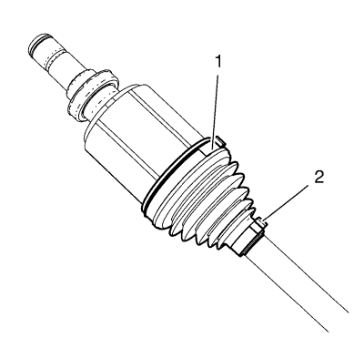
  32. Remove the large seal retaining clamp (1) from the CV joint with a side cutter. Discard the seal retaining clamp.
  33. If equipped with a small swage ring, use a hand grinder to cut through the swage ring, taking care not to damage the halfshaft bar, in order to remove the swage ring. Otherwise, remove the small seal retaining clamp (2) with a side cutter. Discard the retaining clamp.
  34. Slide the seal away from the joint along the halfshaft bar and discard the seal.
  35. Inspect the needle rollers, needle bearings, and trunnion. Check the tripot housing for unusual wear, cracks, or other damage. Replace any damaged parts.

Installation Procedure


    2027976

    Note: Place a towel in the vise before inserting the halfshaft.

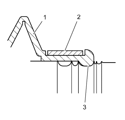
  1. Slide the seal (1) onto the halfshaft bar and position the neck of the outboard seal (1) in the seal groove on the halfshaft bar. The largest groove below the sight groove on the halfshaft bar is the seal groove (3).
  2. Install the new small eared clamp (2) on the neck of the outboard seal (1).
  3. Caution: Refer to Fastener Caution in the Preface section.

    2027983
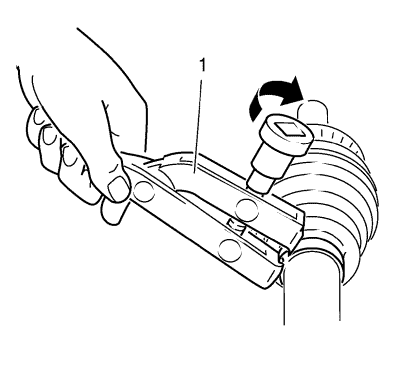
  4. Crimp the eared clamp (1) using the CH-804 tensioner (1), and a torque wrench. Tighten the eared clamp to 25 N·m (19 lb ft).
  5. Place approximately half of the grease from the service kit inside the seal and pack the tripot joint with the remaining grease.
  6. Slide the large diameter of the halfshaft inboard seal, with larger clamp in place, over the outside of the trial tripot bushing and locate the lip of the seal in the groove.
  7. Crimp the seal retaining clamp using CH-804 tensioner (1) to 25 N·m (19 lb ft).

  8. 2027976

    Note: Place a towel in the vise before inserting the halfshaft.

  9. Mount the halfshaft into a vise.
  10. Install the new small eared clamp (2) on the neck of the outboard seal (1). Do not crimp.
  11. Slide the outboard seal (1) onto the halfshaft bar and position the neck of the outboard seal (1) in the seal groove on the halfshaft bar. The largest groove below the sight groove on the halfshaft bar is the seal groove (3).
  12. 2028230
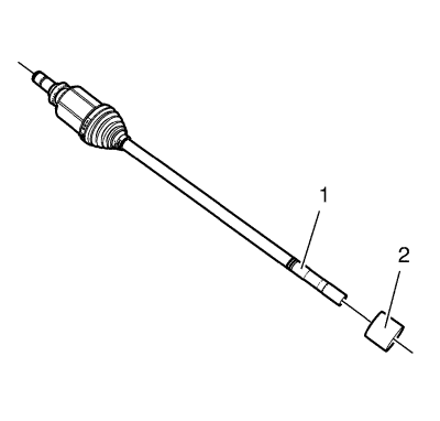
  13. If equipped with a damping wight (2) Install the damping wight (2).
  14. Install retaining clamp (1) at the damping wight (2).
  15. Caution: Refer to Fastener Caution in the Preface section.


    2027983
  16. Crimp the eared clamp using the CH-804 tensioner (1), and a torque wrench. Tighten the eared clamp to 25 N·m (19 lb ft).
  17. 2027968
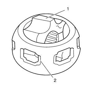
  18. Put a light coat of grease from the service kit on the ball grooves of the inner race and the outer race.
  19. Hold the inner race 90 degrees to centreline of cage with the lands of the inner race (1) aligned with the windows of the cage (2) and insert the inner race into the cage.
  20. 2027965
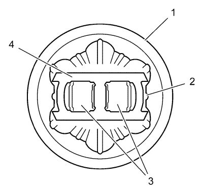
  21. Hold the cage and the inner race 90 degrees to centreline of the outer race (1) and align the cage windows (3) with the lands of the outer race.
  22. Note: Be sure that the retaining ring side of the inner race faces the halfshaft bar.

  23. Place the cage and the inner race into the outer race.
  24. Be sure that the retaining ring side of the inner race faces the halfshaft bar.
  25. Repeat this process until all 6 balls are in place.
  26. Place approximately half the grease from the service kit inside the outboard seal and pack the CV joint with the remaining grease.
  27. 2027984
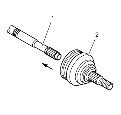
  28. Push the CV joint (2) onto the halfshaft bar (1) until the retaining ring is seated in the groove on the halfshaft bar.
  29. 2027985

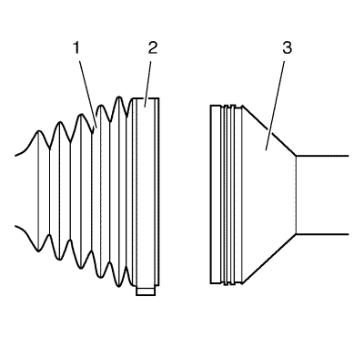
    Note: The outboard seal (1) must not be dimpled, stretched or out of shape in any way. If the outboard seal (1) is not shaped correctly, equalize the pressure in the outboard seal (1) and shape the seal properly by hand.

  30. Slide large diameter of the outboard seal (1) with the large seal retaining clamp (2) in place over the outside of the CV joint outer race (3) and locate the seal lip in the groove on the CV joint outer race.

  31. 2027983
  32. Crimp the seal retaining clamp using CH-804 tensioner (1) to 25 N·m (19 lb ft).


© Copyright Chevrolet. All rights reserved