To the top of the document
Orlando
   
GMDE Start Page Load static TOC Load dynamic TOC Help?

Engine Control Module Wiring Harness Replacement - 2.0L Diesel LNP

Removal Procedure

  1. Open the bonnet.
  2. Remove the battery cover. Refer to Battery Cover Replacement .
  3. Disconnect the battery negative cable. Refer to Battery Negative Cable Disconnection and Connection : without Start/Stop System .

  4. 2506324
  5. Disconnect the 2 engine control module wiring harness plugs (1) from the engine control module (2).

  6. 2506326
  7. Remove the engine control module bracket (2) along with the engine control module (1) from the battery tray (3).
  8. Remove the battery tray. Refer to Battery Tray Replacement .
  9. Remove the windscreen washer solvent container filler tube . Refer to Windscreen Washer Solvent Container Filler Tube Replacement .
  10. Remove the front compartment fuse block. Refer to Front Compartment Fuse Block Replacement .
  11. Remove the engine sight shield. Refer to Engine Sight Shield Replacement .

  12. 2506210
  13. Remove the wiring harness ground cable nut (2) and remove the wiring harness ground cable (3).
  14. Remove the wiring harness plug (1) in top direction from the front compartment fuse block housing.
  15. Disconnect the wiring harness connection adaptor plug (4).
  16. Remove the 2 wiring harness clips from the drivetrain and front suspension frame front inner support and from the charge air cooler outlet hose.

  17. 2511649
  18. Disconnect the exhaust temperature sensor wiring harness plug (5).
  19. Unclip the heated oxygen sensor wiring harness plug (3) from the retainer clip (4) and disconnect the heated oxygen sensor wiring harness plug (3).
  20. Disconnect the exhaust pressure differential sensor hose wiring harness plug (2).
  21. Disconnect the camshaft position sensor wiring harness plug (1).

  22. 2511650
  23. Remove the air cleaner outlet duct. Refer to Air Cleaner Outlet Duct Replacement .
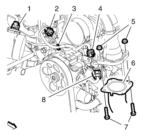
  24. Remove the 2 charge air cooler inlet air hose bolts (7) from the 2 charge air cooler inlet air hose nuts (5). Hang the charge air cooler inlet air hose (6) aside.
  25. Disconnect the exhaust temperature sensor wiring harness plug (2).
  26. Disconnect the exhaust temperature sensor wiring harness plug (4) and unclip the wiring harness clip (3) from the steering pump.
  27. Disconnect the turbocharger wastegate actuator wiring harness plug (8).
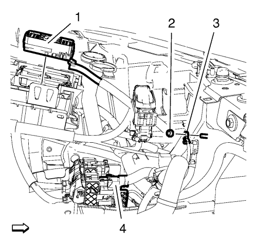
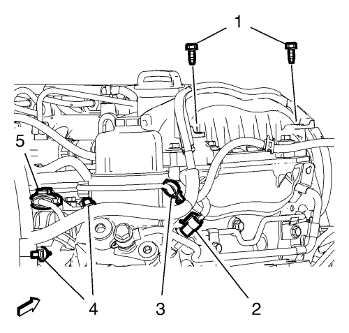
  28. Disconnect the mass air flow sensor wiring harness plug (1) and remove the wiring harness clip from the air filter housing.

  29. 2511653
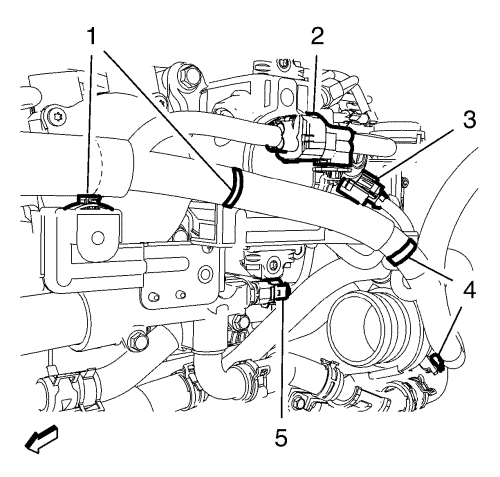
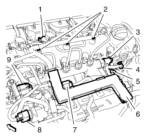
  30. Disconnect the oil pressure sensor wiring harness plug (2).
  31. Remove the wiring harness clip (3) from the charge air control vacuum hose.
  32. Remove the 2 wiring harness channel bolts (1) from the wiring harness channel.
  33. Disconnect the inlet air pressure/temperature sensor wiring harness plug (5).
  34. Disconnect the 2 wiring harness clips (4) from the oil filter assembly and from the inlet manifold.

  35. 2511654
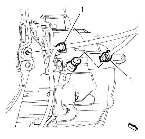
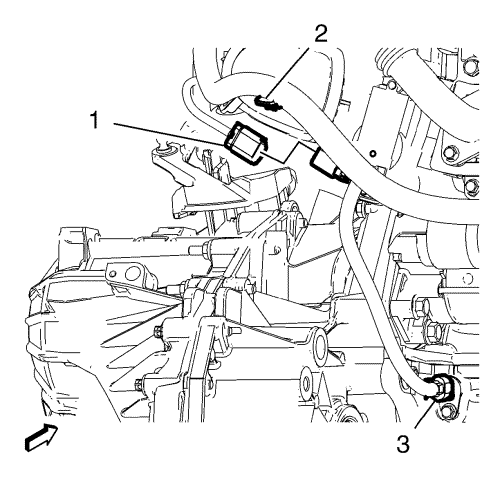
  36. Disconnect the reverse lamp switch wiring harness plug (2) from the transmission.
  37. Remove the wiring harness clip (1) from the transmission.
  38. Raise and support the vehicle. Refer to Lifting and Jacking the Vehicle .
  39. Remove the engine compartment insulator. Refer to Front Compartment Insulator Replacement .

  40. 2511655
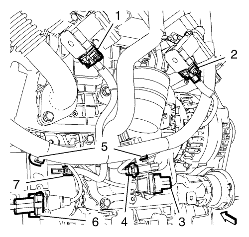
  41. Disconnect the 2 knock sensor wiring harness plugs (3, 6).
  42. Disconnect the alternator wiring harness plug (4).
  43. Disconnect the starter wiring harness plug (7).
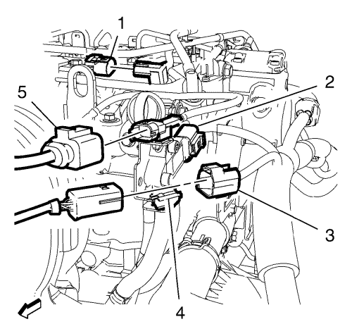
  44. Disconnect the vacuum solenoid valve wiring harness plug (1) and the vacuum solenoid valve wiring harness plug (2).
  45. Remove the 2 wiring harness clips (5) from the 2 brackets.

  46. 2511656
  47. Disconnect the crankshaft position sensor wiring harness plug (3).
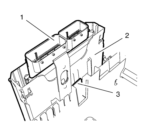
  48. Disconnect the throttle body wiring harness plug (1).
  49. Unclip the wiring harness clip (2) from the charge air cooler outlet hose.

  50. 2511658
  51. Disconnect the air conditioning wiring harness plug (1) and the engine oil level indicator wiring harness plug (2). Hang the wiring harness aside.
  52. Lower the vehicle.

  53. 2511669
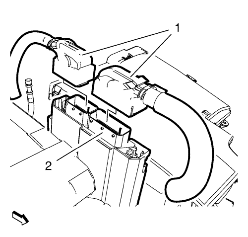
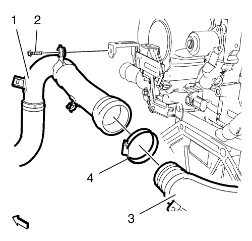
  54. Remove the front charge air cooler outlet hose bolt (2) from the wiring harness bracket.
  55. Remove the front charge air cooler outlet hose clip (4) from the rear charge air cooler outlet hose (3). Hang the front charge air cooler hose (1) aside.

  56. 2511659
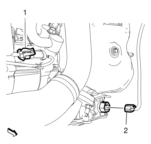
  57. Unclip and disconnect the glow plug wiring harness plug (2) from the engine wiring harness bracket.
  58. Disconnect the fuel pump wiring harness plug (3)
  59. Disconnect the engine coolant temperature sensor wiring harness plug (5).
  60. Unclip the 4 wiring harness clips (1, 4) from the wiring harness bracket.

  61. 2511661
  62. Disconnect the vacuum solenoid valve wiring harness plug (8).
  63. Disconnect the exhaust gas recirculation valve wiring harness plug (9).
  64. Disconnect the inlet actuator valve wiring harness plug (7).
  65. Disconnect the fuel injection rail pressure sensor wiring harness plug (3).
  66. Disconnect the 4 glow plug wiring harness plugs (5).
  67. Disconnect the 4 fuel injector wiring harness plugs (1).
  68. Unclip the 4 engine wiring harness clips (2, 4) from the camshaft cover.
  69. Unclip the engine wiring harness channel (6) in top direction from the 3 exhaust gas recirculation cooler brackets.
  70. Remove the engine wiring harness from the vehicle.

Installation Procedure


    2511661
  1. Position the engine wiring harness on the vehicle.
  2. Clip the engine wiring harness channel (6) to the 3 exhaust gas recirculation cooler brackets.
  3. Clip the 4 engine wiring harness clips (2, 4) to the camshaft cover.
  4. Connect the 4 fuel injector wiring harness plugs (1).
  5. Connect the fuel injection rail pressure sensor wiring harness plug (3).
  6. Connect the 4 glow plug wiring harness plugs (5).
  7. Connect the fuel injection pressure sensor wiring harness plug (3).
  8. Connect the inlet actuator valve wiring harness plug (7).
  9. Connect the exhaust gas recirculation valve wiring harness plug (9).
  10. Connect the vacuum solenoid valve wiring harness plug (8).

  11. 2511659
  12. Clip the 4 wiring harness clips (1, 4) to the wiring harness bracket.
  13. Connect the engine coolant temperature sensor wiring harness plug (5).
  14. Connect the fuel pump wiring harness plug (3).
  15. Clip and connect the glow plug wiring harness plug (2) to the engine wiring harness bracket.
  16. Caution: Refer to Fastener Caution in the Preface section.


    2511669
  17. Position the front charge air cooler outlet hose (1) along with the front charge air cooler outlet hose clip (4) to the rear charge air cooler outlet hose (3) and tighten the clamp to 3.5 N·m (31 lb in).
  18. Install the front charge air cooler outlet hose bolt (2) to the wiring harness bracket and tighten to 10 N·m (89 lb in).
  19. Raise the vehicle.

  20. 2511658
  21. Position the wiring harness.
  22. Connect the air conditioning wiring harness plug (1) and the engine oil level indicator wiring harness plug (2).

  23. 2511656
  24. Clip the wiring harness clip (2) to the charge air cooler outlet hose.
  25. Connect the throttle body wiring harness plug (1).
  26. Connect the crankshaft position sensor wiring harness plug (3).

  27. 2511655
  28. Install the 2 wiring harness clips (5) to the 2 brackets.
  29. Connect the vacuum solenoid valve wiring harness plug (1) and the vacuum solenoid valve wiring harness plug (2).
  30. Connect the starter wiring harness plug (7).
  31. Connect the alternator wiring harness plug (4).
  32. Connect the 2 knock sensor wiring harness plugs (3, 6).
  33. Install the engine compartment insulator. Refer to Front Compartment Insulator Replacement .
  34. Lower the vehicle.

  35. 2511654
  36. Install the wiring harness clip (1) to the transmission.
  37. Connect the reverse lamp switch wiring harness plug (2) to the transmission.

  38. 2511653
  39. Connect the 2 wiring harness clips (4) to the oil filter assembly and to the inlet manifold.
  40. Connect the inlet air pressure/temperature sensor wiring harness plug (5).
  41. Install the 2 wiring harness channel bolts (1) to the wiring harness channel and tighten to 10 N·m (89 lb in).
  42. Install the wiring harness clip (3) to the charge air control vacuum hose.
  43. Connect the oil pressure sensor wiring harness plug (2).

  44. 2511650
  45. Connect the mass air flow sensor wiring harness plug (1) and install the wiring harness clip to the air filter housing.
  46. Connect the turbocharger wastegate actuator wiring harness plug (8).
  47. Connect the exhaust temperature sensor wiring harness plug (4) and clip the wiring harness clip (3) to the steering pump.
  48. Connect the exhaust temperature sensor wiring harness plug (2).
  49. Install the 2 charge air cooler inlet air hose bolts (7) to the 2 charge air cooler inlet air hose nuts (5) and tighten to 22 N·m (16 lb ft)
  50. Install the air cleaner outlet duct. Refer to Air Cleaner Outlet Duct Replacement .

  51. 2511649
  52. Connect the camshaft position sensor wiring harness plug (1).
  53. Connect the exhaust pressure differential sensor hose wiring harness plug (2).
  54. Clip the heated oxygen sensor wiring harness plug (3) to the retainer clip (4) and connect the heated oxygen sensor wiring harness plug (3).
  55. Connect the exhaust temperature sensor wiring harness plug (5).

  56. 2506210
  57. Install the 2 wiring harness clips to the drivetrain and front suspension frame front inner support and to the charge air cooler outlet hose.
  58. Connect the wiring harness connection adaptor plug (4).
  59. Install the wiring harness plug (1) to the front compartment fuse block housing.
  60. Install the wiring harness ground cable (3) and install the wiring harness ground cable nut (2) and tighten to 9 N·m (80 lb in).
  61. Install the front compartment fuse block. Refer to Front Compartment Fuse Block Replacement .
  62. Install the engine sight shield. Refer to Engine Sight Shield Replacement .
  63. Install the windscreen washer solvent container filler tube. Refer to Windscreen Washer Solvent Container Filler Tube Replacement .
  64. Install the battery tray. Refer to Battery Tray Replacement .

  65. 2506326
  66. Install the engine control module bracket (2) along with the engine control module (1) to the battery tray (3).

  67. 2506324
  68. Connect the 2 engine control module wiring harness plugs (1) to the engine control module (2).
  69. Connect the battery negative cable. Refer to Battery Negative Cable Disconnection and Connection : without Start/Stop System .
  70. Install the battery cover. Refer to Battery Cover Replacement .
  71. Close the bonnet.


© Copyright Chevrolet. All rights reserved


© Copyright Chevrolet. All rights reserved