Oil Pressure Diagnosis and Testing
Special Tools
| • | EN-135 Adapter Oil Pressure Check |
| • | GE-498-B Oil Pressure Gauge |
For equivalent regional tools, refer to Special Tools .
Removal Procedure
- Disconnect the battery negative cable. Refer to
Battery Negative Cable Disconnection and Connection : without Start/Stop System .
- Remove the engine sight shield. Refer to Engine Sight Shield Replacement .
- Remove the air cleaner assembly. Refer to Air Cleaner Assembly Replacement .
- Clip the power steering fluid reservoir outlet hose out of the 2 mounts and hang aside.
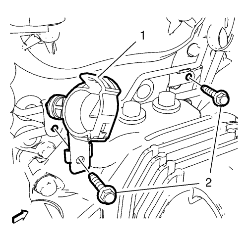
- Remove the 2 bolts (2) from the mount brackets. Remove the power steering fluid reservoir outlet hose bracket (1).
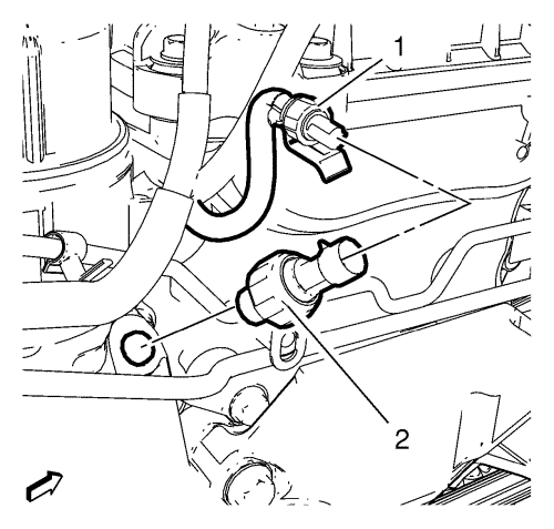
- Disconnect the oil pressure switch wiring harness plug (1) from the engine oil pressure switch (2).
- Remove the engine oil pressure switch (2).
Measurement Procedure
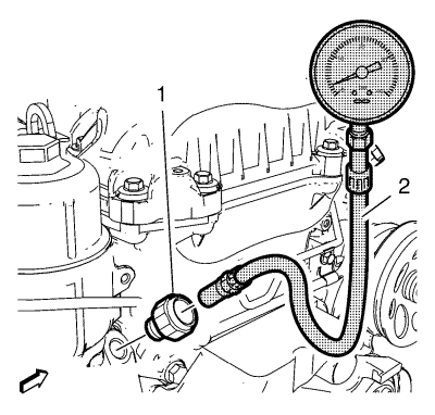
- Install the EN-135 adaptor (1).
- Install the GE-498-B gauge (2) to the EN-135 adaptor (1).
- Install the mass air flow sensor to the air filter outlet duct.
- Connect the mass air flow sensor wiring harness plug to the mass air flow sensor.
- Connect the battery negative cable. Refer to
Battery Negative Cable Disconnection and Connection : without Start/Stop System .
- Start the engine.
- Check the oil pressure.
- Compare the values with those from the engine mechanical specifications. Refer to Engine Mechanical Specifications .
- Turn off the engine.
- Disconnect the battery negative cable. Refer to
Battery Negative Cable Disconnection and Connection : without Start/Stop System .
- Disconnect the mass air flow sensor wiring harness plug from the mass air flow sensor.
- Remove the mass air flow sensor from the air filter outlet duct.
- Remove the GE-498-B gauge (2).
- Remove the EN-135 adaptor (1).
Installation Procedure
Caution: Refer to Fastener Caution in the Preface section.
- Install the engine oil pressure switch and tighten to 20 N·m (15 lb ft).
- Connect the oil pressure switch wiring harness plug (1) to the engine oil pressure switch (2).
- Install the power steering fluid reservoir outlet hose mount bracket (1). Install the 2 bolts (2) to the mount brackets and tighten to 10 N·m (89 lb in).
- Clip the power steering fluid reservoir outlet hose into the 2 mounts.
- Install the air cleaner assembly. Refer to Air Cleaner Assembly Replacement .
- Install the engine sight shield. Refer to Engine Sight Shield Replacement .
- Connect the battery negative cable. Refer to
Battery Negative Cable Disconnection and Connection : without Start/Stop System .
| © Copyright Chevrolet. All rights reserved |
| © Copyright Chevrolet. All rights reserved |


