Cylinder Head Replacement
Special Tools
| • | EN-6333 Timing Belt Tensioner Locking Pin |
| • | EN-6340 Camshaft Locking Tool |
| • | EN-6625 Crankshaft Locking Device |
| • | EN-45059 Torque Angle Sensor Kit |
For equivalent regional tools, refer to Special Tools .
Removal Procedure
- Remove the intake manifold. Refer to Inlet Manifold Replacement .
- Remove the exhaust manifold. Refer to
Exhaust Manifold Replacement : 2.0L Diesel LNP → 1.6L LDE, LXV, 1.8L 2H0, LUW and LFH .
- Remove the timing belt upper front cover. Refer to
Timing Belt Upper Front Cover Removal : LDE, LED, LFJ, LXV, 2H0, LUW, LFH .
- Raise and support the vehicle. Refer to Lifting and Jacking the Vehicle .
- Remove the front compartment splash shield. Refer to Front Compartment Splash Shield Replacement .
- Remove the drive belt tensioner. Refer to Drive Belt Tensioner Replacement .
- Lower the vehicle.
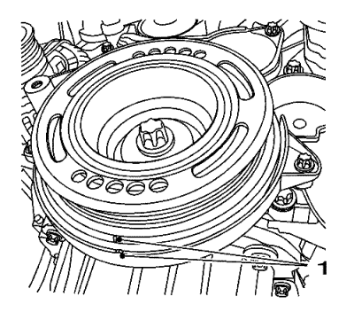
- Set crankshaft balancer in direction of engine rotation to "cylinder 1 TDC of combustion stroke" (1).
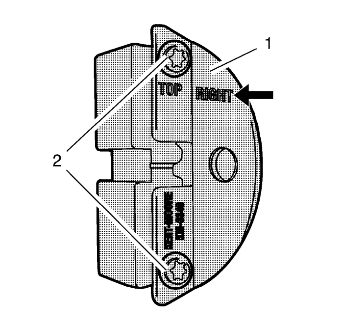
- Prepare the right half of the EN-6340 locking tool.
| 9.1. | Remove the 2 bolts (2). |
| 9.2. | Remove the front panel (1) |
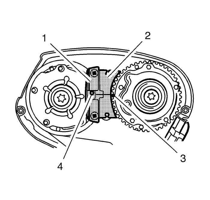
- Install the EN-6340 locking tool into the camshaft adjusters.
| | Note: The spot type marking (4) on the inlet camshaft adjuster does not correspond to the groove of EN-6340-left locking tool during this process but must be somewhat above as shown. |
| • | Install the EN-6340-left locking tool (1) in the camshaft adjusters as shown. |
| | Note: The spot type marking (3) on the exhaust camshaft adjuster must correspond to the groove on EN-6340-right locking tool . |
| • | Install EN-6340-right locking tool (2) in the camshaft adjusters as shown. |
- Remove EN-6340 locking tool.
- Raise the vehicle.
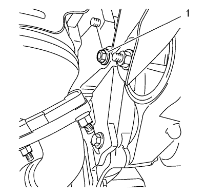
- Remove the bolt (1).
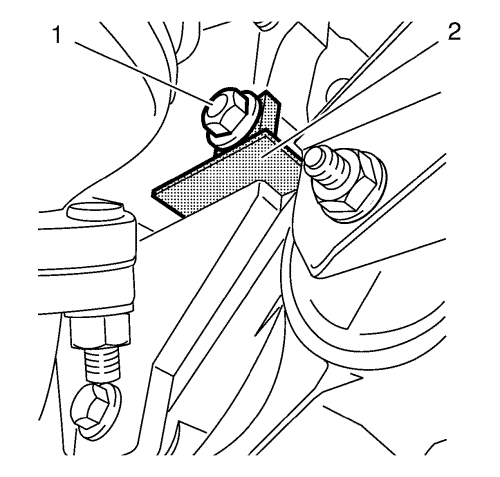
- Install EN-6625 locking device (2) to block the crankshaft.
- Install the bolt (1).
- Remove the crankshaft balancer. Refer to Crankshaft Balancer Removal .
Note: The SPX installation manual is supplied with the special tool and is also available online from SPX directly. Go to www.spxtools-shop.com.
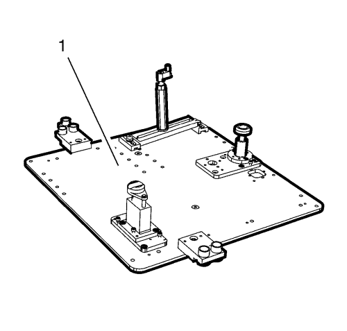
- Assemble the CH-49290 support tool (1) according to the details provided in the SPX installation manual.
- Support the CH-904 base frame on a jack.
- Support the CH-49290 support tool on the CH-904 base frame .
Note: The SPX installation manual is supplied with the special tool and is also available online from SPX directly. Go to www.spxtools-shop.com.
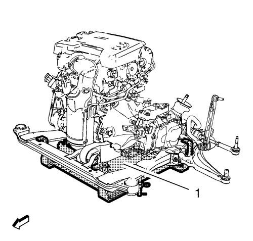
- Install the CH-49290 support tool (1) according to the details provided in the SPX installation manual.
- Remove the engine mount bracket. Refer to Engine Mount Bracket Replacement .
- Remove the timing belt centre front cover. Refer to Timing Belt Centre Front Cover Removal .
- Remove the timing belt lower front cover. Refer to Timing Belt Lower Front Cover Removal .
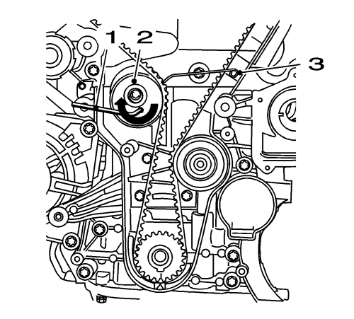
- Loosen the timing belt tensioner bolt.
- Apply tension to the drive belt tensioner (2) in the direction of the arrow, using an Allen key (1).
- Install the EN-6333 locking pin (3).
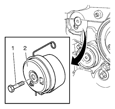
- Remove the timing belt tensioner bolt (1) and the timing belt tensioner (2).
- Remove the camshaft cover. Refer to
Camshaft Cover Replacement : 1.6L LDE, LXV, 1.8L 2H0, LUW and LFH .
- Remove the 2 camshaft position sensor. Refer to
Camshaft Position Sensor Replacement : LDE, LXV, LUW, 2H0 and LFH .
- Remove the 2 camshaft position actuator solenoid valve. Refer to Camshaft Position Actuator Solenoid Valve Replacement .
- Remove the 2 camshaft position actuator adjusters. Refer to Camshaft Position Actuator Adjuster Removal .
- Remove the timing belt rear cover. Refer to Timing Belt Rear Cover Removal .
- Remove engine coolant thermostat housing. Refer to
Engine Coolant Thermostat Replacement : 2.0L Diesel LNP → 1.6L LDE, LXV, 1.8L LUW, 2H0 and LFH .
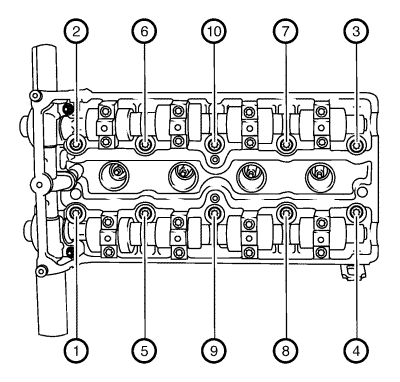
- Remove the 10 cylinder head bolts in sequence as shown, using the EN-45059 sensor kit .
| 34.1. | Loosen the 10 bolts 90°. |
| 34.2. | Loosen the 10 bolts 180°. |
- Remove the cylinder head and place on a suitable base.
- Remove and discard the cylinder head gasket.
Installation Procedure
- Clean the sealing surfaces.
- Inspect for plane surface.
| 2.1. | Cylinder block, cylinder head |
| 2.2. | Straight-edge, feeler gage |
- Install a NEW cylinder head gasket.
- Install the cylinder head.
Caution: Refer to Fastener Caution in the Preface section.
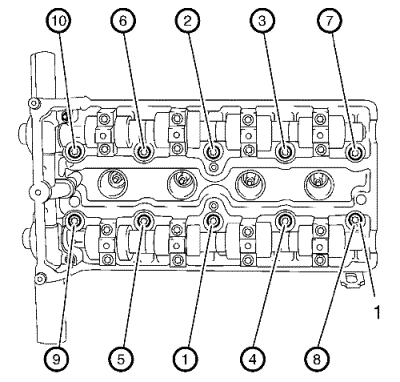
Note: Note the correct tightening sequence.
- Install 10 NEW cylinder head bolts (1).
- Tighten the bolts in 5 passes. Use the EN-45059 sensor kit .
| 6.1. | First pass to 25 N·m (18 lb ft) |
- Install engine coolant thermostat housing. Refer to
Engine Coolant Thermostat Replacement : 2.0L Diesel LNP → 1.6L LDE, LXV, 1.8L LUW, 2H0 and LFH .
- Install the timing belt rear cover. Refer to Timing Belt Rear Cover Installation .
- Install the camshaft position actuator adjuster. Refer to Camshaft Position Actuator Adjuster Installation .
- Install the camshaft position actuator solenoid valve. Refer to Camshaft Position Actuator Solenoid Valve Replacement .
- Install the 2 camshaft position sensor. Refer to
Camshaft Position Sensor Replacement : LDE, LXV, LUW, 2H0 and LFH .
- Install the camshaft cover. Refer to
Camshaft Cover Replacement : 1.6L LDE, LXV, 1.8L 2H0, LUW and LFH .
- Clean the timing belt tensioner thread.
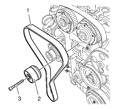
- Install the timing belt tensioner (2).
- Install the timing belt tensioner bolt (3).
- Apply tension to the drive belt tensioner (2) in the direction of the arrow, using an Allen key (1).
- Remove the EN-6333 locking pin (3).
Note: The timing belt tensioner moves automatically to the correct position.
- Release tension on timing belt tensioner.
Caution: Refer to Fastener Caution in the Preface section.
- Tighten the timing belt tensioner bolt to 20 N·m (15 lb ft).
- Install the timing belt lower front cover. Refer to Timing Belt Lower Front Cover Installation .
- Install the timing belt centre front cover. Refer to Timing Belt Centre Front Cover Installation .
- Install the engine mount bracket. Refer to Engine Mount Bracket Replacement .
- Raise the vehicle.
- Lower the CH-49290 support tool (1) with the CH-904 base frame and a jack.
- Remove the CH-49290 support tool from the CH-904 base frame .
Note: The SPX installation manual is supplied with the special tool and is also available online from SPX directly. Go to www.spxtools-shop.com.
- Disassemble the CH-49290 support tool (1) according to the details provided in the SPX installation manual.
- Install the crankshaft balancer. Refer to Crankshaft Balancer Installation .
- Remove bolt (1).
- Remove EN-6625 locking device (2) to block the crankshaft.
- Install the bolt (1) and tighten to 75 N·m (55 lb ft).
- Lower the vehicle.
- Check the timing
| | Note: Note the marking at the camshaft sprockets. |
| • | Turn the crankshaft 720° in the direction of engine rotation by the bolt on the crankshaft balancer. |
| | Note: The spot type marking (4) on the inlet camshaft adjuster does not correspond to the groove of EN-6340-left locking tool during this process but must be somewhat above as shown. |
| • | Install EN-6340-left locking tool (1) into the camshaft adjusters as shown. |
| | Note: The spot type marking (3) on the exhaust camshaft adjuster must correspond to the groove on EN-6340-right locking tool . |
| • | Install EN-6340-right locking tool (2) into the camshaft adjusters as shown. |
Note: Note the marking at the crankshaft balancer and the cover.
- Control the crankshaft balancer position.
Markings on torsional crankshaft balancer (1) and lower cover (1) must align.
- Install the drive belt tensioner. Refer to Drive Belt Tensioner Replacement .
- Install the front compartment splash shield. Refer to Front Compartment Splash Shield Replacement .
- Lower the vehicle.
- Remove the EN-6340 locking tool.
- Install the timing belt upper front cover. Refer to
Timing Belt Upper Front Cover Installation : LDE, LED, LFJ, LXV, 2H0, LUW, LFH .
- Install the exhaust manifold. Refer to
Exhaust Manifold Replacement : 2.0L Diesel LNP → 1.6L LDE, LXV, 1.8L 2H0, LUW and LFH .
- Install the inlet manifold. Refer to Inlet Manifold Replacement .
- Fill the cooling system. Refer to Cooling System Draining and Filling .
- Check and correct the engine oil.
| © Copyright Chevrolet. All rights reserved |
| © Copyright Chevrolet. All rights reserved |


