Note: Coat the transmission inner parts with gear fluid when installing.
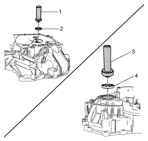
- Install the new input shaft oil seal (2) using the DT-50179 input shaft seal installation tool (1).
- Install the new differential right side oil seal (4) using the DT-49088 oil seal installation tool (3).
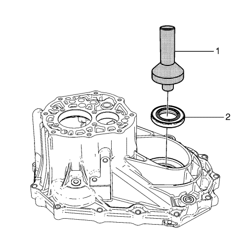
- Install the new differential left side oil seal (2) using the DT-50181 oil seal installation tool (1).
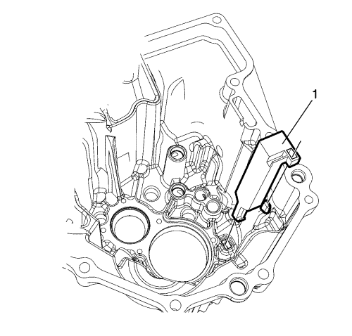
- Install the oil gutter (1).
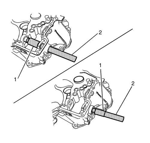
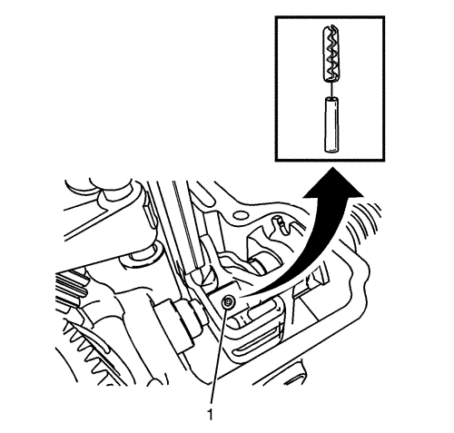
- Install the shift and selector shaft needle bearing using the DT-49083 needle bearing installation tool (1) and DT-49082 needle bearing removal/installation tool (2).
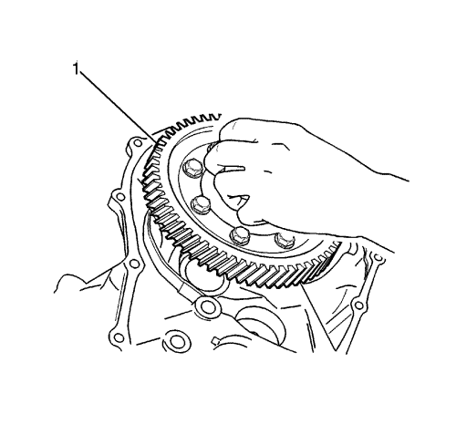
- Install the differential assembly (1) to the right side of the transmission case. Position the differential ring gear surface lower than the right side of the transmission case surface.
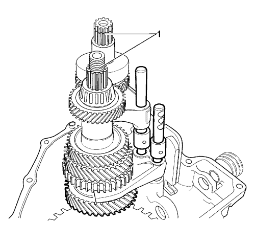
- Install the low- and high-speed shift shaft assembly onto the gear unit.
Note: Do NOT damage the teeth of the layshaft pinion and the differential ring gear.
- Push the gear unit (1) by matching the unit with the input and the layshaft hole.
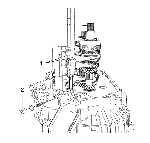
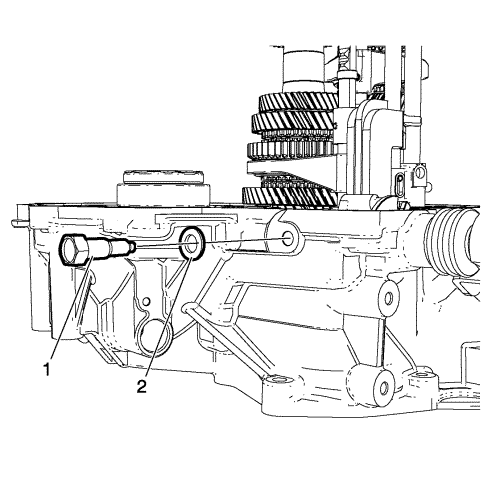
- Install the 5th and reverse gear shift shaft (1).
Caution: Refer to Fastener Caution in the Preface section.
- Install the 5th and reverse gear shift shaft ball, spring, washer and bolt (2) and tighten to 13 N·m (10 lb ft).
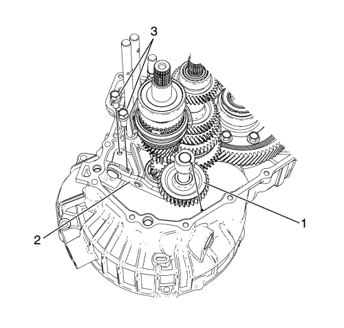
Note: Match the marking of the reverse idle gear shaft bolt hole with the protrusion of the transmission case - right side.
- Install the reverse idle gear shaft assembly (1).
- Install the reverse gear gear lever (2).
- Install the reverse gear gear lever bolts (3) and tighten to 23 N·m (17 lb ft).
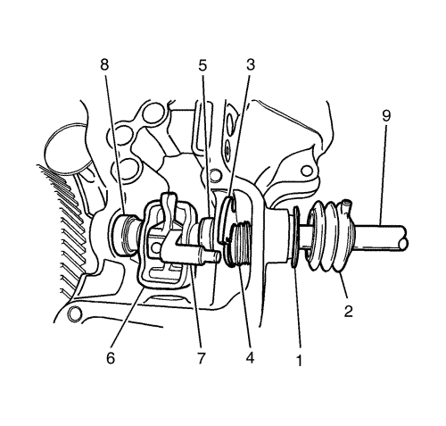
- Install the shift and selector shaft oil seal (1).
- Install the shift and select bellows (2).
- Install the 5th and reverse gear shift cam (3)
- Install the return spring (4).
- Install the gear select spring assembly (5).
- Install the gear shift interlock plate (6).
- Install the gear gear lever (7).
- Install the gear select spring assembly (8).
- Install the shift and select shaft (9).
Note: When installing the inner and outer pins, make the crevices of 2 pins symmetric to each other.
- Install the new shift and the select lever inner and outer pins (1).
- Install the shift interlock washer (2) and bolt (1) and tighten to 23 N·m (17 lb ft).
- Coat the transmission case with recommended transmission case sealant - THREE BOND 1215 or LOCTITE 5702.
- Install the transmission left side case to the transmission right side case.
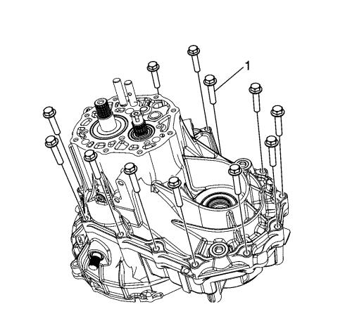
- Install 12 bolts (1) onto the left side case and tighten to 19 N·m (14 lb ft).
- Install the bolts (1) onto the right case and tighten to 19 N·m (14 lb ft).
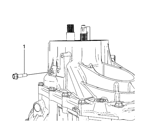
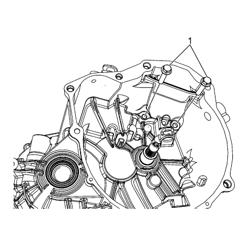
- Install the reverse idle gear shaft bolt (1) and tighten to 23 N·m (17 lb ft).
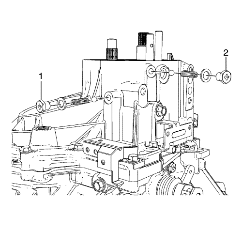
- Install the 3rd-4th gear shift shaft ball, spring, washer and bolt (2) and tighten to 13 N·m (10 lb ft).
- Tighten the low-speed (1, 2 gear) shift shaft ball, spring, washer, and bolt (1) to install the 1st-2nd gear shift shaft ball, spring, washer and bolt (1) and tighten to 13 N·m (10 lb ft).
Note: Check if the bearing and the outer race are correctly installed by rotating the layshaft.
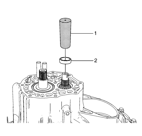
- Install the layshaft bearing outer race (2) using the DT-46496 gear, bearing installation tool (1).
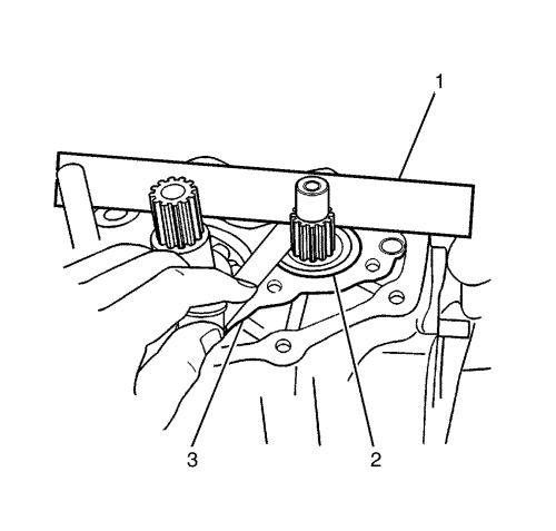
- Measure the clearance between the transmission case surface (3) and the bearing outer race (2) using a straight ruler (1) and a gauge. Refer to Transmission Case Surface and Bearing Outer Races Clearance Table in Manual Gearbox Specifications
- Select a shim so that clearance is within standard.
- Install the layshaft bearing shim.
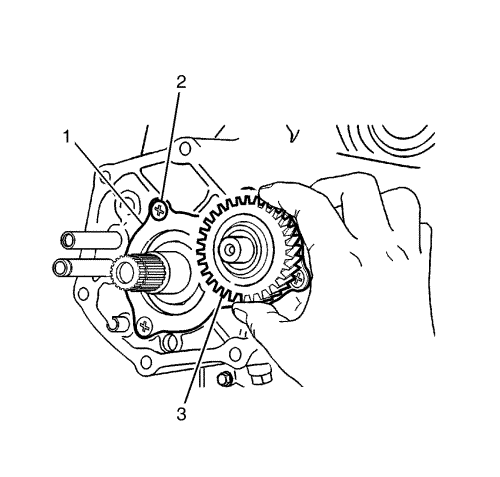
- Install the left case plate (1).
- Install the 6 new left case plate screws (2) and tighten to 8 N·m (71 lb in).
Note: Position the machined boss side toward the side cover plate.
- Install the layshaft 5th gear (3).
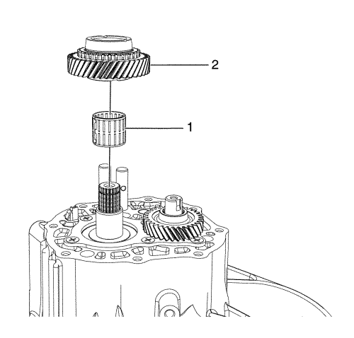
- Insert the input shaft 5th gear bearing (1) into the input shaft.
- Install the input shaft 5th gear (2).
Note: Make sure that the lever mark must be showed after assembly.
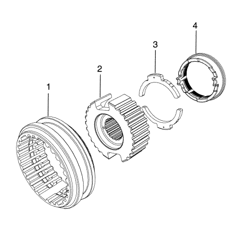
- Assemble the 5th gear synchroniser hub assembly.
| • | Position the longer boss side of hub (2) toward inner side. |
| • | Position the chamfered spline of sleeve (1) toward inner side and install the hub (2) to the sleeve (1). |
| • | Position the lever marks side toward outer side and install the levers (3) into the hub (2). |
| • | Install the synchroniser ring (4) inserting ring lugs into the spaces between levers (3). |
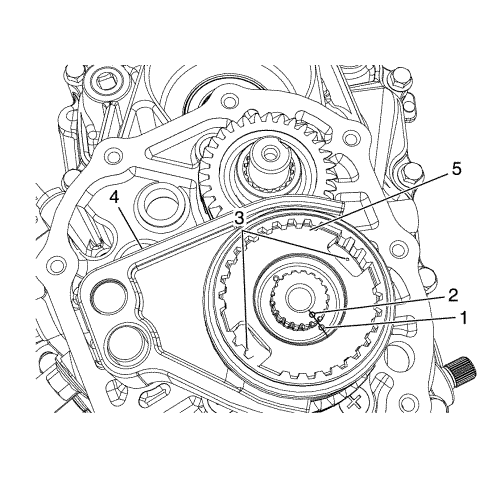
Note: Position the longer boss side of hub toward inner side and match the hub mark (1) with the input shaft punched mark (2). Make sure that the lever marks (3) must be showed to the 5th synchroniser hub assembly.
- Install 5th gear fork to the synchroniser hub assembly.
- Install the 5 gear fork (4) and synchroniser hub assembly (5) to the input shaft.
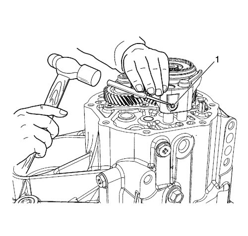
- Install the new 5th gear selector fork pin (1) using a pin punch and hammer.
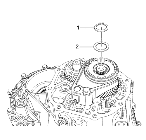
- Install the 5th gear synchroniser hub plate (2).
- Install the new input shaft circlip (1).
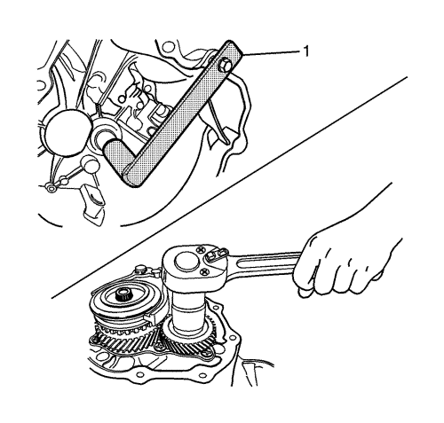
- Move the shift shaft lever into the 5th gear position.
- Hold the input shaft using the DT-49084 input shaft holder (1).
- Install the new layshaft nut and tighten to 70 N·m (52 lb ft).
- Caulk the nut using a chisel and hammer.
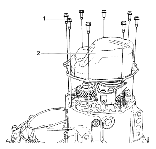
- Coat the side cover with recommended Side Cover Sealant-THREE BOND 1215 or LOCTITE 5702.
- Install the side cover (2).
- Install 8 side cover bolts (1) and tighten to 10 N·m (89 lb in).
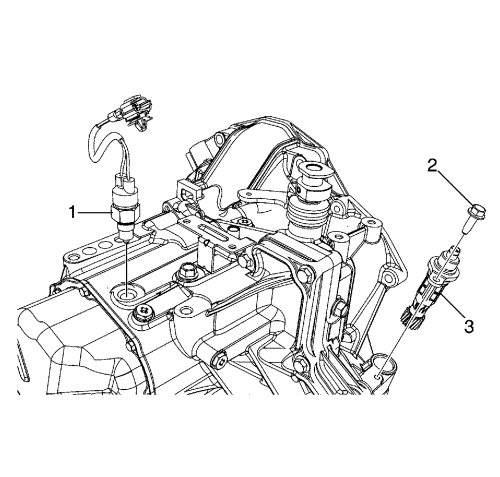
- Install the speedometer driven gear assembly (3).
- Install the speedometer driven gear bolt (2) and tighten to 6 N·m (53 lb in).
- Install the reverse light switch (1) and tighten to 17 N·m (13 lb ft).
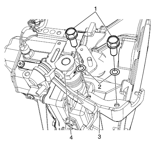
- Install the selector and gear lever cable bracket (3) and bush (4).
- Install the selector and gear lever cable bracket washers (2) and bolts (1) and tighten to 23 N·m (17 lb ft).
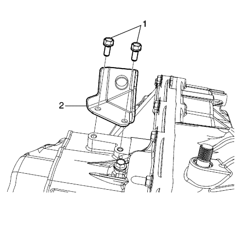
- Install the clutch cable bracket (2) and bolts (1) and tighten to 23 N·m (17 lb ft).
- Install the clutch release bearing, shaft, and bushing. Refer to Clutch Release Bearing Replacement .
- Install the clutch release arm. Refer to Clutch Pedal Arm Replacement .
- Install the transmission assembly. Refer to Transmission Replacement .


