Spark
Brake Pedal Assembly Replacement — Left Hand Drive
Removal Procedure
Remove the steering column opening filler. Refer to
Steering Column Opening Filler Replacement
.
Remove the steering column lower trim cover. Refer to
Steering Column Lower Trim Cover Replacement
.
Remove the intermediate steering shaft. Refer to
Intermediate Steering Shaft Replacement
.
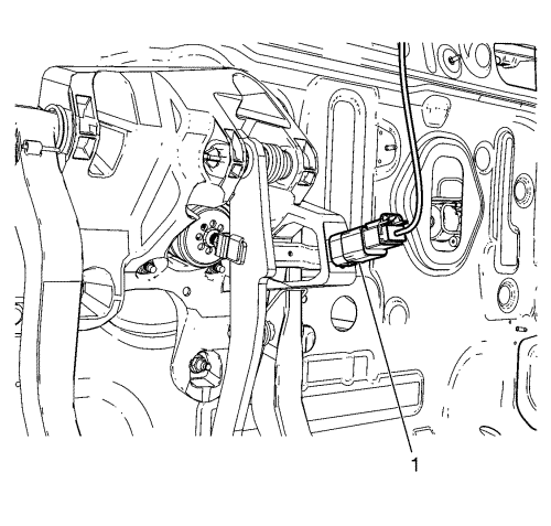
Disconnect the electrical connector of the stop lamp switch (1).
Disconnect the accelerator cable from the accelerator pedal by pulling and raising the cable end (1).
Lift up the cable end retaining spring (1) and disconnect the clutch cable (2) from the clutch pedal, if equipped. Refer to
Clutch Cable Replacement
.
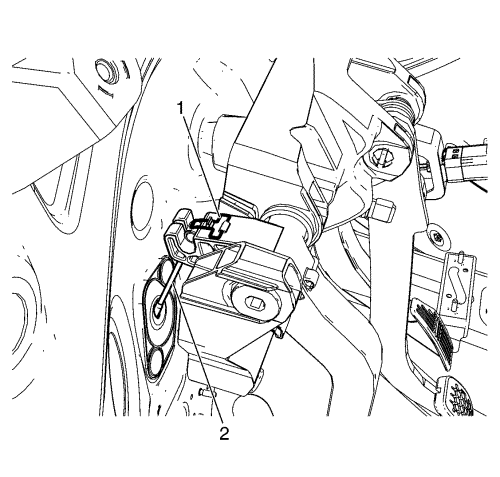
Remove the retaining clip (1) and pin (2) from the brake pedal.
Release the brake booster pushrod from the brake pedal.
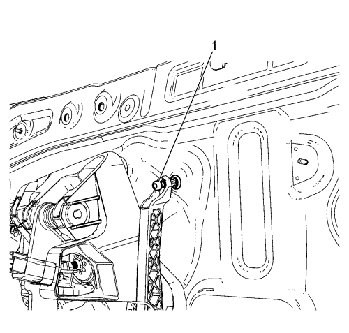
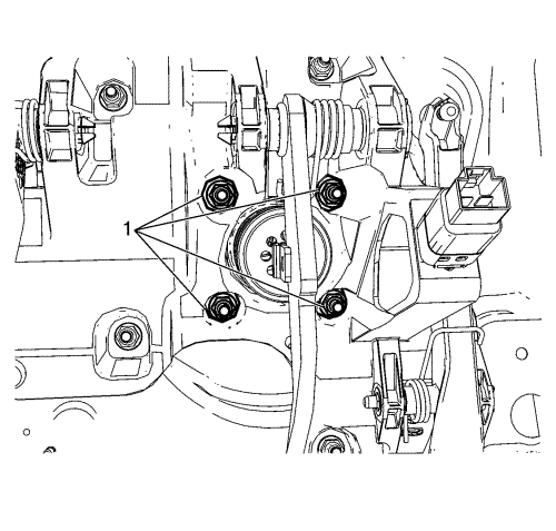
Remove the brake booster-to-accelerator, brake and clutch (ABC) pedal module retaining nuts (1) from the ABC pedal module.
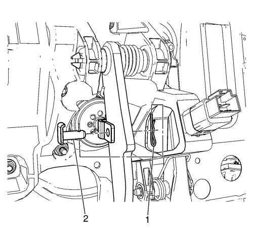
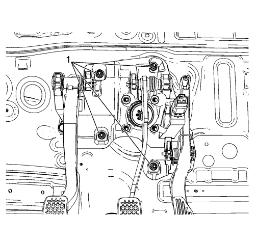
Remove the ABC module-to-dash panel retaining nuts (1) from the ABC pedal module.
Remove the ABC pedal module from the vehicle.
Remove the accelerator pedal from the ABC pedal module, if necessary.
Installation Procedure
Install the accelerator pedal to the ABC pedal module, if necessary.
Install the ABC pedal module into the vehicle.
Caution:
Refer to
Fastener Caution
in the Preface section.
Install the ABC module-to-dash panel retaining nuts (1) and tighten to
22 N·m (16 lb ft)
.
Loosely install the brake booster-to-ABC pedal module retaining nuts (1).
Connect the brake booster pushrod to the brake pedal.
Install the pushrod pin (2) to the brake pedal and insert the retaining clip (1) to the pin (2).
Completely tighten the brake booster-to-ABC pedal module retaining nuts (1) and tighten to
22 N·m (16 lb ft)
.
Connect the clutch cable to the clutch pedal, if equipped. Refer to
Clutch Cable Replacement
.
Connect the accelerator cable to the accelerator pedal.
Connect the electrical connector of the stop lamp switch.
Install the intermediate steering shaft. Refer to
Intermediate Steering Shaft Replacement
.
Install the steering column lower trim cover. Refer to
Steering Column Lower Trim Cover Replacement
.
Install the steering column opening filler. Refer to
Steering Column Opening Filler Replacement
.
© Copyright Chevrolet. All rights reserved