Crankshaft and Bearing Cleaning and Inspection
Cleaning Procedure
- Clean the crankshaft with solvent.
- Thoroughly clean all oil passages and inspect for restrictions or burrs.
Warning: Refer to Safety Glasses and Compressed Air Warning in the Preface section.
- Dry the crankshaft with compressed air.
Visual Inspection
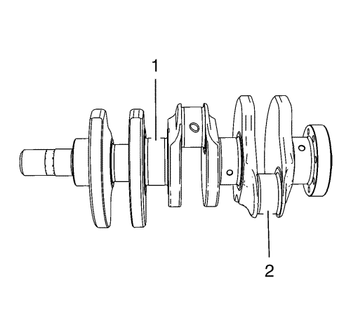
- Inspect the 4 crankshaft bearing journals (1) and the 3 connecting rod bearing journals (2) for wear:
| • | pitting or embedded bearing material |
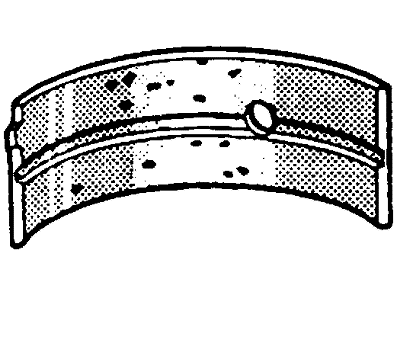
- Inspect the crankshaft bearings for craters or pockets. Flattened sections on the bearing halves also indicate fatigue.
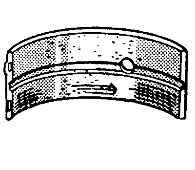
- Inspect the crankshaft bearings for excessive scoring or discolouration.
- Inspect the crankshaft bearings for dirt or debris imbedded into the bearing material.
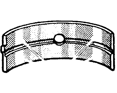
- Inspect the crankshaft bearings for improper seating indicated by bright, polished sections of the bearing.
Note: If the lower half of the bearing is worn or damaged, both upper and lower halves should be replaced.
Generally, if the lower half is suitable for use, the upper half should also be suitable for use.
Check Crankshaft Bearing Clearance (With Micrometer Gauge Internal Measuring Device)
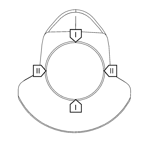
- Measurement the crankshaft bearing journal diameter with a micrometre gauge at the measuring points (I) and (II).
- Calculate the average crankshaft bearing journal diameter. Formula: 1. result + 2. result / 2.
Refer to Engine Mechanical Specifications for the recommended limits.
- Crankshaft bearing clearance is calculated by using:
| • | crankshaft bearing journal diameter |
| • | crankshaft bearing shell thickness |
| | Note: Different classes of bearing shells can be used for a crankshaft bearing to reduce bearing clearance. The stronger of the two bearing shells must be inserted in the crankcase. |
- Determine the crankshaft bearing clearance.
Calculation formula: average crankshaft bearing bore diameter minus average crankshaft bearing journal diameter minus crankshaft bearing shell thickness from lower crankcase minus crankshaft bearing shell thickness from engine block.
Refer to Engine Mechanical Specifications for the recommended limits.
Check Crankshaft Bearing Clearance (With Plastigage)
- Install crankshaft with the 5 upper crankshaft bearing shells at the engine block.
Note: Do not rotate the crankshaft.
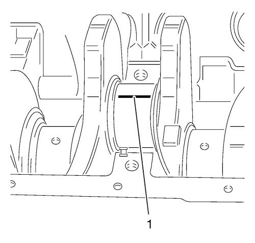
- Lay on 4x plastigage (flexible plastic thread) axially over the entire width of the crankshaft bearing journal (1).
- Install the 4 lower crankshaft bearing shells.
Note: Only reuse the old bolts for the measurement.
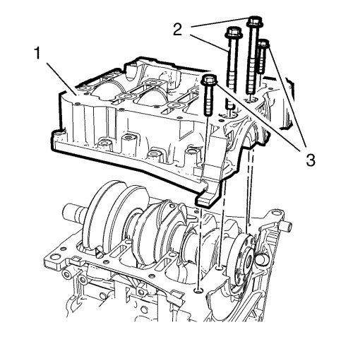
- Install the lower crankcase (1)
- Loosely install the 8 lower crankcase inner bolts (2).
- Loosely install the 8 lower crankcase outer bolts (3).
Caution: Refer to Fastener Caution in the Preface section.
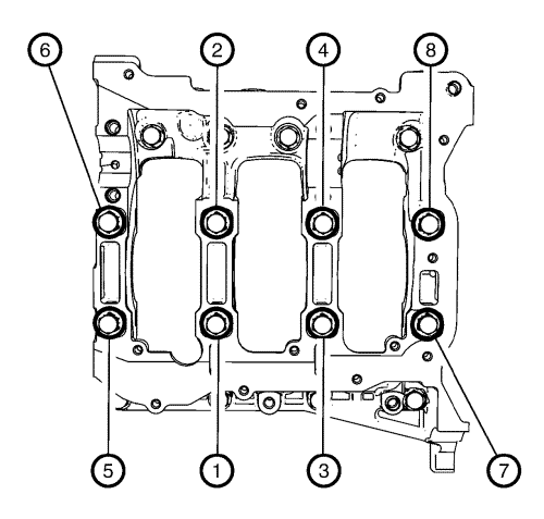
- Tighten the 10 lower crankcase inner bolts in sequence as shown and in the following order:
| • | Tighten the bolts in sequence as shown to 20 N·m (15 lb ft). |
| • | Tighten in sequence as shown to an additional 80 °. |
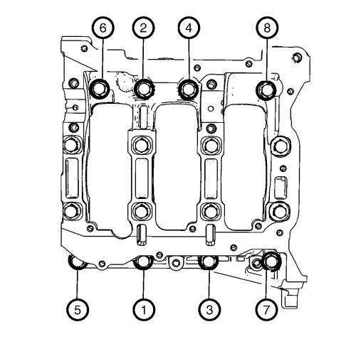
- Tighten the 8 lower crankcase outer bolts in sequence as shown to 30 N·m (22 lb ft).
- Detach the crankcase.
- Remove and DISCARD the 8 lower crankcase outer bolts (3).
- Remove and DISCARD the 8 lower crankcase inner bolts (2).
- Remove lower crankcase (1).
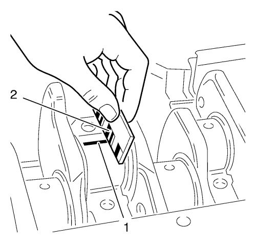
Note: When reading the value, do not confuse millimetres and inches on the measuring scale.
- Measure the crankshaft bearing play.
| • | Compare the width of the flattened plastic thread (1) to the measuring scale (2). |
| © Copyright Chevrolet. All rights reserved |


