Cylinder Leakage Test
Special Tools
| • | EN-46783 Thread Adapter |
| • | EN-46785 Fixing Tool Crankshaft |
| • | EN-50515 Fixing Tool Camshaft |
For equivalent regional tools, refer to Special Tools .
Removal Procedure
- Remove the fuel injector. Refer to Fuel Injector Replacement .
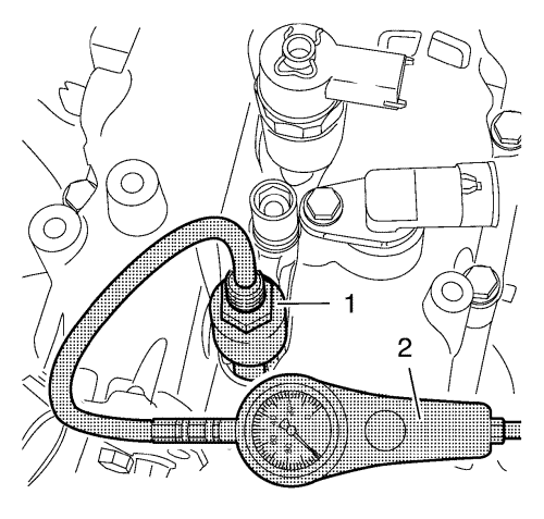
- Clean the injector sealing surfaces in the cylinder head using the EN-47632 cleaning tool (1) in following procedure:
| 2.1. | first use the brush side to loosen the dirt. |
| 2.2. | second use the sponge side to remove the dirt. |
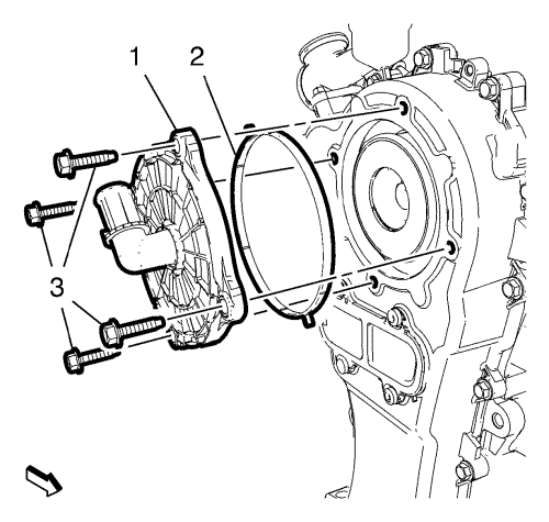
- Remove the 4 positive crankcase ventilation cover bolts (3).
- Remove the positive crankcase ventilation cover (1).
- Remove the positive crankcase ventilation cover gasket (2).
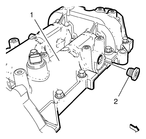
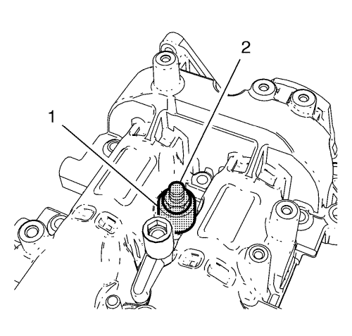
- Remove the cylinder head core hole plug exhaust side (2) from the camshaft housing (1).
- Clean the threads from cylinder head core hole plug and the camshaft housing.
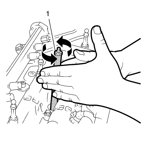
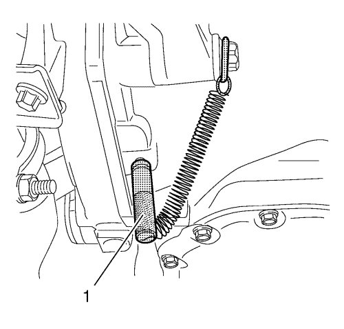
- Install the EN-50515 fixing tool (1) on exhaust side.
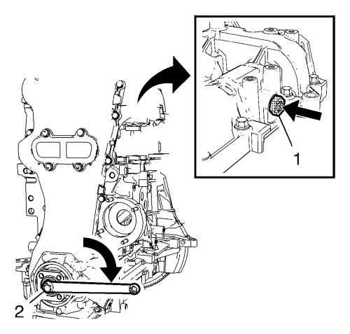
- Apply pressure to the EN-50515 fixing tool (arrow) and turn crankshaft at crankshaft sprocket bolt (2) carefully in engine direction of rotation (arrow), until EN-50515 fixing tool (1) becomes engaged in the exhaust camshaft.
Note: The cylinder 1 is on TDC if the EN-50515 fixing tool and EN-46785 fixing tool are installed.
- Turn the crankshaft carefully until the EN-46785 fixing tool (1) engages in the flywheel.
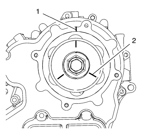
Note: The marking is necessary to adjust the TDC of the individual cylinders.
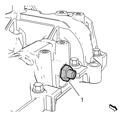
- Make a marking on the oil pump housing (1) and 3 check marks on the oil separator (2).
- Remove the EN-46785 fixing tool and the EN-50515 fixing tool .
Test Procedure Cylinder 1
- Calibrate the pressure loss meter.
- Engage 4th gear and apply the park brake.
Note: EN-46791 adapter can only be installed in pairs along with the fuel injector at cylinder 1 and cylinder 2.
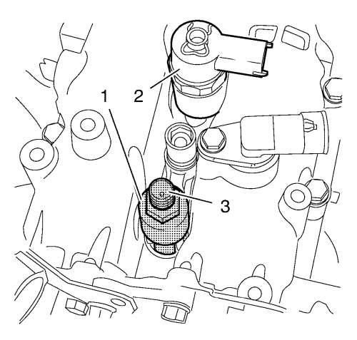
- Install the EN-46791 adapter (1) along with the fuel injector (2) and the fuel injector bracket in cylinder 1 with a NEW fuel injector gasket.
- Install the fuel injector washer.
Caution: Refer to Fastener Caution in the Preface section.
- Install the fuel injector bracket nut and tighten to 25 N·m (18 lb ft).
- Install the EN-46783 thread adapter (3) to the EN-46791 adapter (1).
- Install the pressure loss tester (2) to the EN-46783 thread adapter (1).
- Pressurise cylinder 1.
- Check pressure loss in cylinder 1.
| • | Max. pressure difference between the individual cylinders 10% approx. |
| • | The pressure loss per cylinder should not exceed 25%. |
| • | Check escaping air to localise the damage on: |
| - | Oil dipstick guide tube |
- Remove the fuel injector bracket nut cylinder 1 and 2.
- Remove the fuel injector washer.
- Remove the fuel injector cylinder 2 and pressure loss tester along with the EN-46791 adapter from cylinder 1.
Test Procedure Cylinder 3
- Set the transmission to neutral.
- Turn the engine 240° by crankshaft.
| | Note: Note the alignment marking on camshaft sprocket bolt. |
| • | Turn the crankshaft in the direction of the engine rotation by the bolt on the torsional vibration damper flange. |
| • | Engage 4th gear and apply the park brake. |
- Install the EN-46791 adapter (1) and the fuel injector bracket in cylinder 3 with a NEW fuel injector gasket.
- Install the fuel injector washer.
- Install the fuel injector bracket nut and tighten to 25 N·m (18 lb ft).
- Install the EN-46783 thread adapter (2) to the EN-46791 adapter (1).
- Install the pressure loss tester (2) to the EN-46783 thread adapter (1).
- Pressurise cylinder 3.
- Check pressure loss in cylinder 3.
| • | Max. pressure difference between the individual cylinders 10% approx. |
| • | The pressure loss per cylinder should not exceed 25%. |
| • | Check escaping air to localise the damage on: |
| - | Oil dipstick guide tube |
- Remove the fuel injector bracket nut .
- Remove the fuel injector washer.
- Remove the pressure loss tester along with the EN-46791 adapter from the cylinder 3.
Test Procedure Cylinder 2
- Set the transmission to neutral.
- Turn the engine 240° by crankshaft.
| | Note: Note the alignment marking on camshaft sprocket bolt. |
| • | Turn the crankshaft in the direction of the engine rotation by the bolt on the torsional vibration damper flange. |
| • | Engage 4th gear and apply the park brake. |
Note: EN-46791 adapter can only be installed in pairs along with the fuel injector at cylinder 1 and cylinder 2.
- Install EN-46791 adapter (1) along with the fuel injector (2) and fuel injector bracket in cylinder 2 with a NEW fuel injector gasket.
- Install the fuel injector washer.
- Install the fuel injector bracket nut and tighten to 25 N·m (18 lb ft).
- Install the EN-46783 thread adapter (3) to the EN-46791 adapter (1).
- Install the pressure loss tester (2) to the EN-46783 thread adapter (1).
- Pressurise cylinder 2.
- Check pressure loss in cylinder 2.
| • | Max. pressure difference between the individual cylinders 10% approx. |
| • | The pressure loss per cylinder should not exceed 25%. |
| • | Check escaping air to localise the damage on: |
| - | Oil dipstick guide tube |
- Remove the fuel injector bracket nut cylinder 1 and 2.
- Remove the fuel injector washer.
- Remove the fuel injector cylinder 1 and pressure loss tester with the EN-46791 adapter from the cylinder 2.
Installation Procedure
- Remove the EN-46785 fixing tool (1).
- Remove the EN-50515 fixing tool (1) from exhaust side.
- Install the camshaft housing core hole plug exhaust side (2) to the camshaft housing (1) and tighten to 15 N·m (11 lb ft).
- Install the positive crankcase ventilation cover gasket (2).
- Install the positive crankcase ventilation cover (1).
- Install the 4 positive crankcase ventilation cover bolts (3) and tighten in a cross sequence to 10 N·m (89 lb in).
- Install the fuel injector. Refer to Fuel Injector Installation .
| © Copyright Chevrolet. All rights reserved |


