Brake Pressure Modulator Valve Replacement
Removal Procedure
Warning: Refer to Brake Fluid Irritant Warning in the Preface section.
Caution: Refer to Brake Fluid Effects on Paint and Electrical Components Caution in the Preface section.
Caution: Always connect or disconnect the wiring harness connector from the EBCM/EBTCM with the ignition switch in the OFF position. Failure to observe this precaution could result in damage to the EBCM/EBTCM.
- Turn the ignition switch to the OFF position.
- Remove the underhood electrical center.
- Without draining the coolant or removing the hoses, remove and position aside the radiator surge tank. Refer to
Radiator Surge Tank Replacement : Diesel → Petrol Engines .
- Disconnect the electronic brake control module (EBCM) electrical connector by lifting the locking tabs.
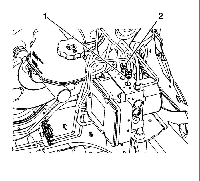
- Disconnect the left front brake pipe fitting (1) at the brake pressure modulator valve (BPMV).
- Cap the brake pipe fitting and plug the BPMV outlet port to prevent brake fluid loss and contamination.
- Disconnect the right front brake pipe fitting (2) from the BPMV.
- Cap the brake pipe fitting and plug the BPMV outlet port to prevent brake fluid loss and contamination.
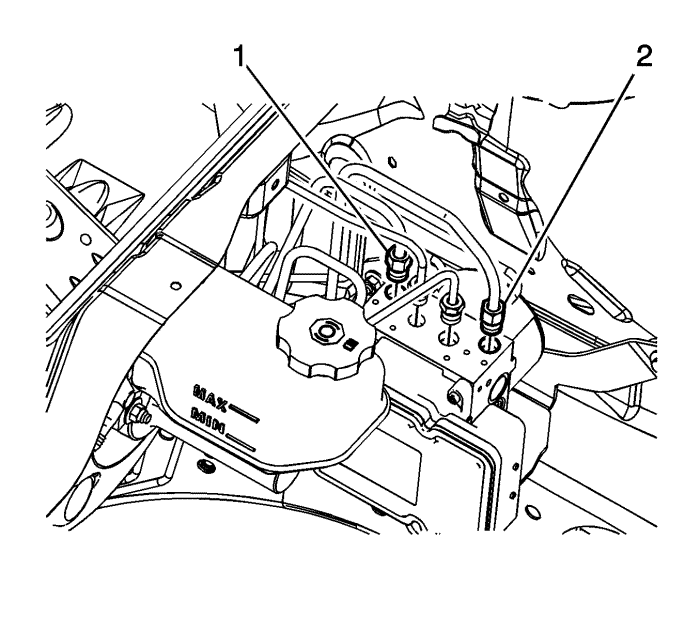
- Disconnect the master cylinder primary brake pipe fitting (1) from the BPMV.
- Cap the brake pipe fitting and plug the BPMV inlet port to prevent brake fluid loss and contamination.
- Disconnect the master cylinder secondary brake pipe fitting (2) from the BPMV.
- Cap the brake pipe fitting and plug the BPMV inlet port to prevent brake fluid loss and contamination.
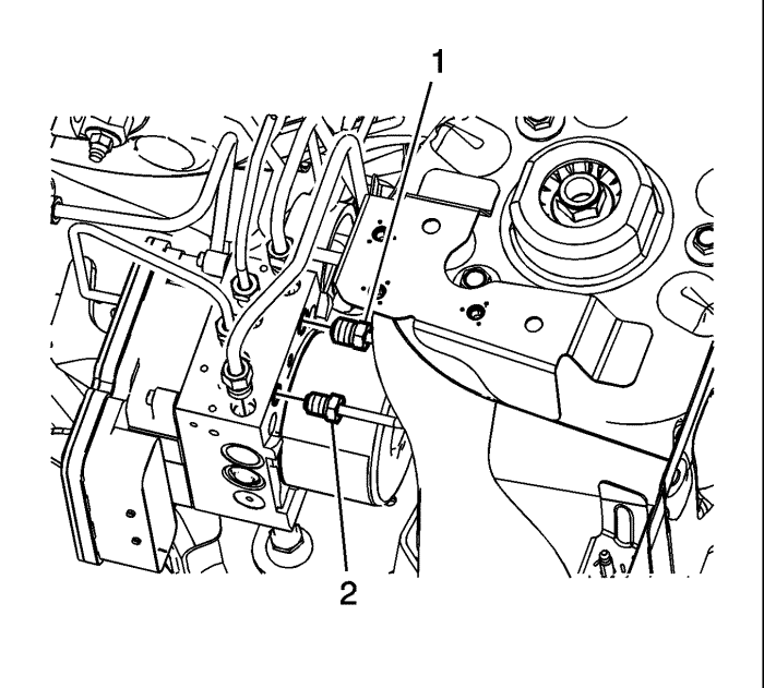
- Disconnect the left rear brake pipe fitting (1) from the BPMV.
- Cap the brake pipe fitting and plug the BPMV outlet port to prevent brake fluid loss and contamination.
- Disconnect the right rear brake pipe fitting (2) from the BPMV.
- Cap the brake pipe fitting and plug the BPMV outlet port to prevent brake fluid loss and contamination.
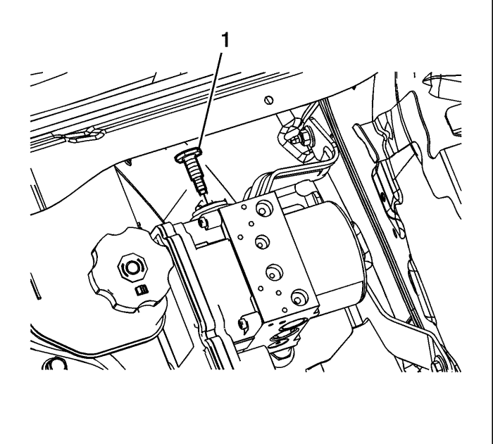
- Remove the BPMV bolt (1).
Note: Do not pry on the accumulator caps on the underside of the BPMV.
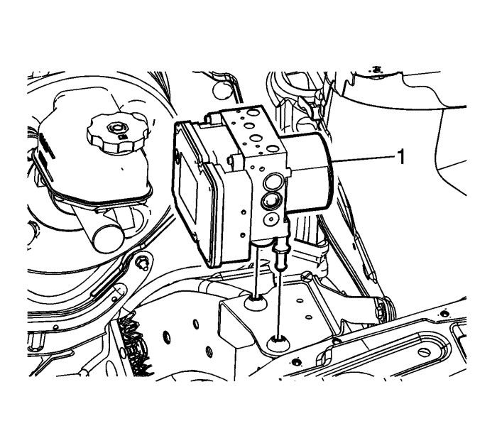
- Carefully remove the BPMV assembly (1) by pulling straight upward.
- Inspect the insulators for damage and replace, if necessary.
Installation Procedure
- Install the BPMV assembly (1) to the bracket.
Caution: Refer to Fastener Caution in the Preface section.
- Install the BPMV bolt (1) and tighten to 10 N·m (89 lb in).
- Connect the left rear brake pipe fitting (1) to the BPMV and tighten to 21 N·m (16 lb ft).
- Connect the right rear brake pipe fitting (2) to the BPMV and tighten to 21 N·m (16 lb ft).
- Connect the master cylinder primary brake pipe fitting (1) to the BPMV and tighten to 21 N·m (16 lb ft).
- Connect the master cylinder secondary brake pipe fitting (2) to the BPMV and tighten to 21 N·m (16 lb ft).
- Connect the left front brake pipe fitting (1) to the BPMV and tighten to 21 N·m (16 lb ft).
- Connect the right front brake pipe fitting (2) to the BPMV and tighten to 21 N·m (16 lb ft).
- Connect the EBCM electrical connector.
- Install the radiator surge tank. Refer to
Radiator Surge Tank Replacement : Diesel → Petrol Engines .
- Install the underhood electrical center.
- Bleed the hydraulic brake system. Refer to
Hydraulic Brake System Bleeding : Manual → Pressure .
- Turn the ignition switch to the ON position.
- Perform the Diagnostic System Check - Vehicle .
- Observe the brake pedal feel after performing the diagnostic system check. If the pedal now feels spongy, air may have been in, or may have been introduced into the primary circuit.
- If the pedal feels spongy, perform the Antilock Brake System Automated Bleed .
| © Copyright Chevrolet. All rights reserved |


