- Remove the camshaft cover. Refer to Camshaft Cover Replacement - Right Side .
- Remove the camshaft position actuator solenoid valve solenoid - intake. Refer to Camshaft Position Actuator Solenoid Valve Solenoid Replacement - Bank 1 (Right Side) Intake .
- Remove the intake camshaft position sensor. Refer to Camshaft Position Sensor Replacement - Bank 1 (Right Side) Intake .
- Remove the exhaust camshaft position sensor. Refer to Camshaft Position Sensor Replacement - Bank 1 (Right Side) Exhaust .
- Remove the camshaft position actuator solenoid valve solenoid - exhaust. Refer to Camshaft Position Actuator Solenoid Valve Solenoid Replacement - Bank 1 (Right Side) Exhaust .
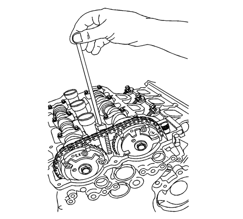
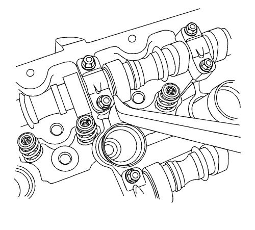
- Rotate engine clockwise using crankshaft dampener retaining bolt until the flats at the rear ends of the camshafts are pointing up. This puts the camshafts on "base circle" and will reduce their tendency to rotate from valve spring pressure when the camshaft position actuators/drive chains are removed.
Note: Do NOT remove or back out the camshaft position actuator bolt(s) significantly, simply break them loose from their fully-torqued position. The position actuators must stay firmly attached until the retaining tools are in place, but they should be broken loose while the chain is still tight and in position.
- Loosen intake and/or exhaust camshaft position actuator retaining bolts, depending on which camshaft position actuator and/or camshaft you will be servicing. If servicing both camshaft position actuators and/or camshafts, loosen both bolts.
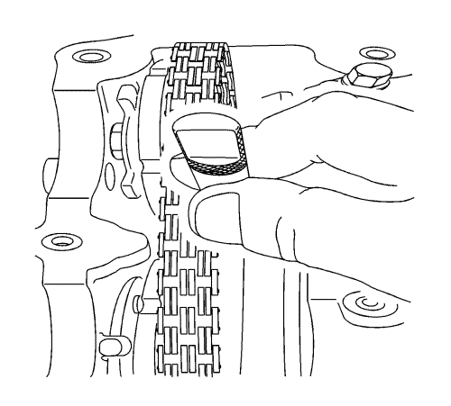
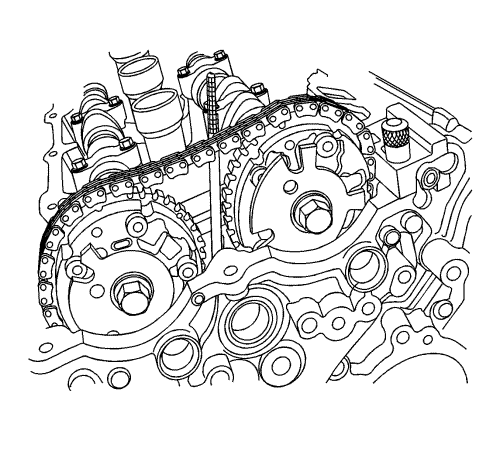
Note: Be certain to clearly mark the position of the chain to the camshaft position actuator(s). Though the engine does not need to be set to a specific timing mark before starting the procedure, the relationship of the chain to the actuator(s) is critical and must be re-established on assembly.
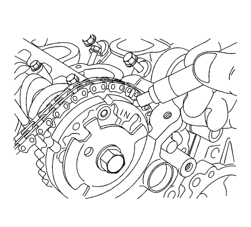
- Mark the position of the chain to the camshaft position actuator - intake.
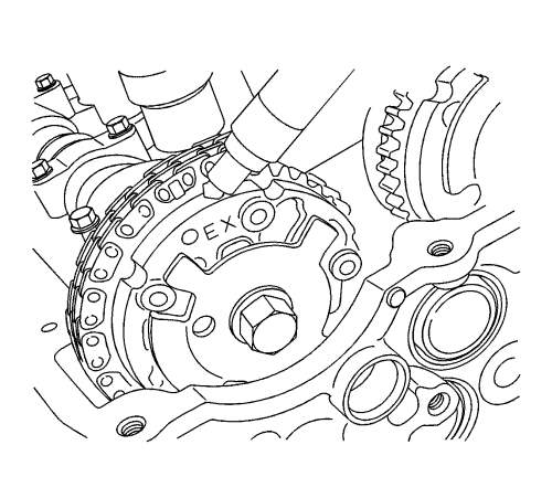
- Mark the position of the chain to the camshaft position actuator - exhaust.
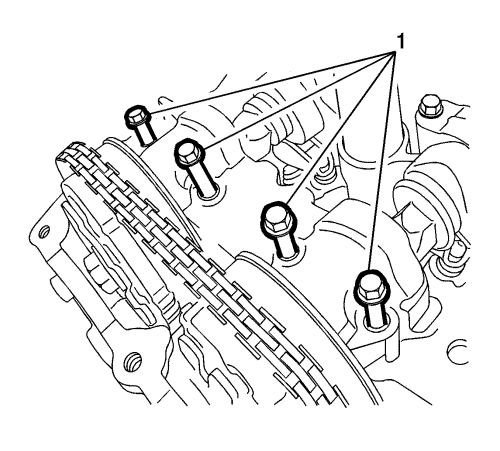
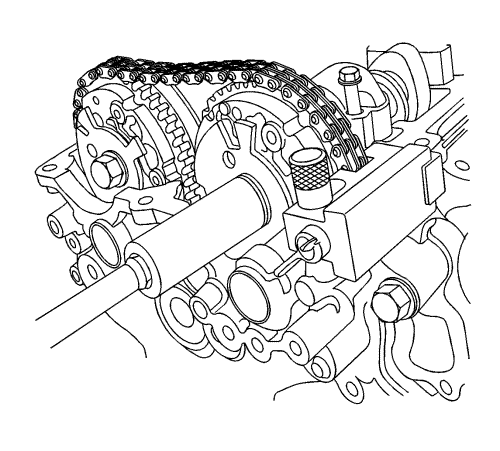
- Remove camshaft front cap bolts (1).
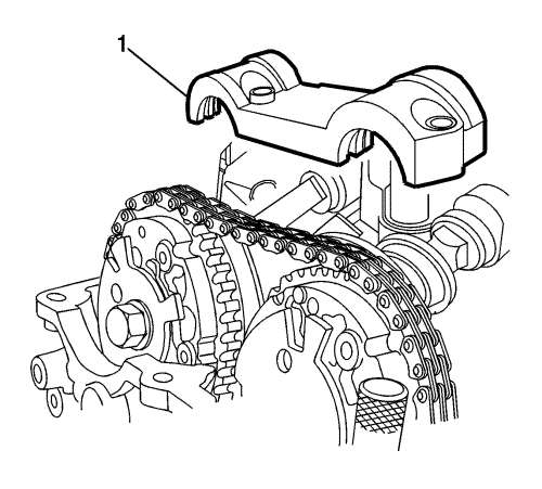
Note: Do NOT remove or loosen any other camshaft bearing caps at this time, even if you intend to eventually remove the camshaft.
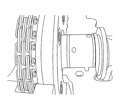
- Remove the camshaft front cap (1).

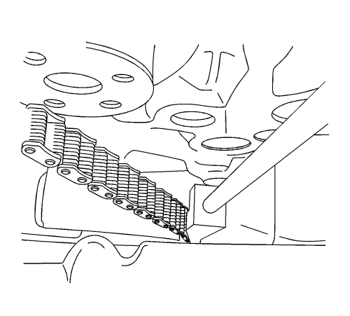
- Loosen wing nut (4) to open the clamping area of EN49982-1 retainer .
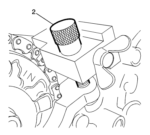
Note: Do NOT overtighten the thumbscrew. The EN49982-1 retainer should be able to slide slightly via the slot the screw goes through. This fore/aft movement will allow easier removal and installation of the chain later.
- Install EN49982-1 retainer intake side chain holder onto front cover by screwing in the thumbscrew (2) on the EN49982-1 retainer finger-tight.
Note: Do NOT tighten the wing nut with a tool of any kind. Firm finger-tightening is sufficient.
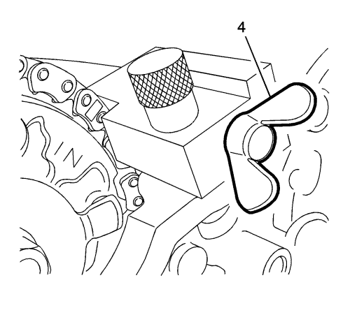
- Tighten wing nut (4) so EN49982-1 retainer closes over and firmly grasps the timing chain.
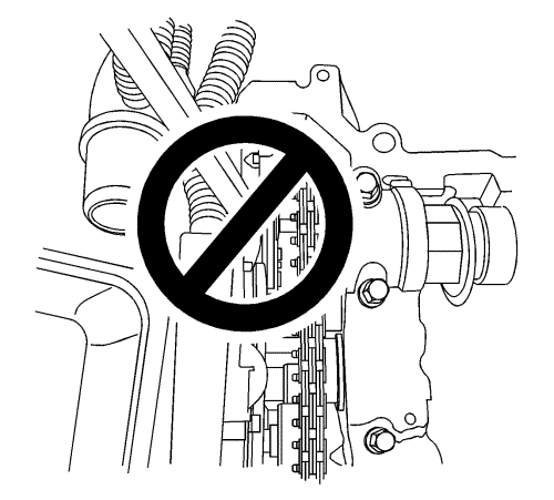
Note: The engine front cover is removed for clarity in the following graphics, but is NOT required to be removed to perform the procedure.
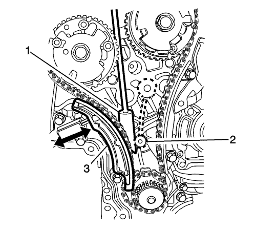
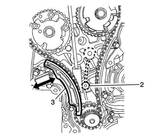
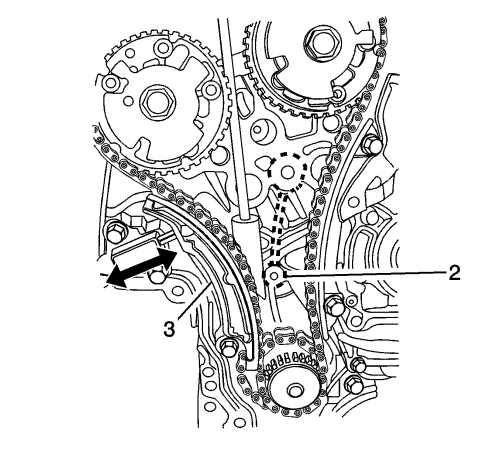
- EN49982-2 retainer (1) will be installed in the following steps such that it wedges between an internal rib (2) that is cast into the inside of the front cover (shown in dotted line above) and the timing chain and spring-loaded tensioner shoe (3), holding the chain in position. The wedge will be left in place during the cam position actuator and/or camshaft service.
- Insert the EN49982-2 retainer between the two camshaft position actuators with the "teeth" on theEN49982-2 retainer facing toward the front cover.
- Once the wedge portion of EN49982-2 retainer is below the camshaft position actuators, rotate the EN49982-2 retainer until the flat in the handle faces toward the intake camshaft position actuator. This orients the "teeth" toward the chain.
Note: Do not try to force the wedge into position, simply ensure it is loosely engaged in the timing chain and in the correct overall position.
- Drop the wedge down until it begins to engage the timing chain and the belt casting (2).
- If possible, shine a strong light down from above, between the camshaft position actuators, and see the wedge in overall position as shown in the above graphic.
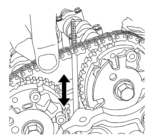
- Using a 20 mm wrench on the cast hexagonal portion of the exhaust camshaft, rotate the camshaft toward the intake camshaft while pushing down on the handle of the EN49982-2 retainer .
- This rotation of the camshaft will compress the tensioner shoe (3) against the spring force of the tensioner, opening up a gap between the chain and the internal rib in the front cover. The wedge will then drop into this gap. You will feel a distinct click as the teeth engage the chain.
Caution: Be sure the EN49982-2 is captured firmly as described before continuing. This is critical to ensuring the camshaft drive chains stay properly timed.
- Release the force on the wrench, allowing the spring tension to close the tensioner shoe against the wedge portion of EN49982-2 retainer . You should be able to lightly tug on the EN49982-2 retainer and it should stay in position. Repeat Steps 20 and 21 if necessary to re-insert the EN49982-2 retainer until you are certain it is in position and will stay in position.
- With EN49982-2 retainer in position and with the 20 mm wrench removed, there should now be some slack in the timing drive chain as indicated in the graphics shown.
- Do not prize against the face of the camshaft position actuators or the position actuator retaining bolt.
Caution: Do not prize against the face of the camshaft position actuators or the position actuator retaining bolts as the position actuators will be damaged.
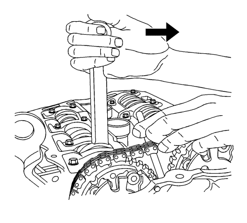
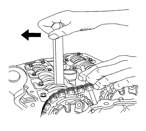
- Position a screwdriver or small pry bar between a camshaft cap and camshaft lobe. Carefully move/prize the camshafts as far as possible toward the rear/flywheel end of the engine.
Note: Do not move or disturb the EN49982 retainer components after their installation or the timing chains may be lost inside the front cover.
- The EN49982-1 retainer and EN49982-2 retainer should be in position as shown, they must be left in position during the servicing of the camshaft position actuator(s) and/or camshaft(s).
- Remove and capture the plastic thrust washers (1) in the following steps. Ensure the plastic thrust washer does not fall into the front cover area.
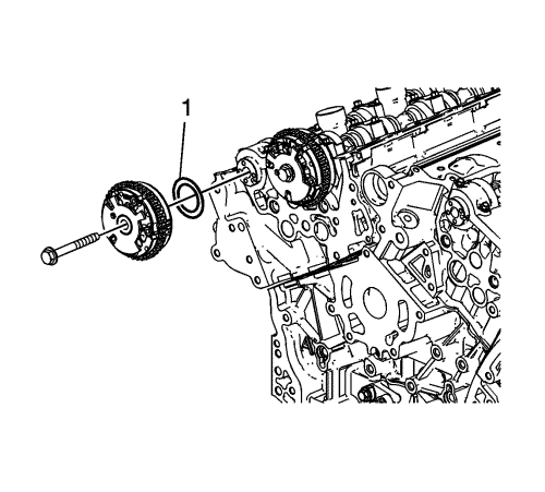
- To remove the intake camshaft position actuator, remove the loosened retaining bolt. To remove only the exhaust camshaft position actuator, skip the steps for removing the intake camshaft position actuator. However, the EN49982-1 retainer MUST be installed as discussed even if the intake side will not be serviced or the timing of the camshaft chains will be lost.
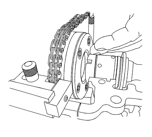
- Slide the camshaft position actuator forward and off the end of the intake camshaft. The slot in the EN49982-1 retainer will allow the tool to move forward enough to disengage the camshaft position actuator from the front of the camshaft. Remove the plastic thrust washer when removing the camshaft position actuator from the end of the camshaft.
- Tilt the camshaft position actuator forward and out/away from the engine.
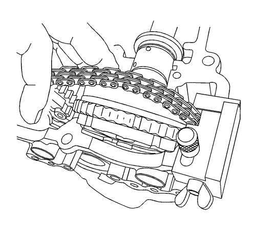
Note: DO NOT remove the EN49982 retainers . They are holding the cam chains to maintain their properly-timed positions.
- Allow the chain to rest on the EN49982-1 retainer and EN49982-2 retainer in position during service.