Captiva |
||||||||
|
|
|
|||||||
The fuel system is an electronic returnless on-demand design. The returnless fuel system reduces the internal temperature of the fuel tank by not returning hot fuel from the engine to the fuel tank. Reducing the internal temperature of the fuel tank results in lower evaporative emissions.
An electric turbine style fuel pump attaches to the fuel pump module inside the fuel tank. The fuel pump supplies high pressure fuel through the fuel feed pipe to the fuel injection system. The fuel pump module contains a reverse flow check valve. The check valve maintains fuel pressure in the fuel feed pipe and the fuel rail in order to prevent long cranking times.
E85 compatible vehicles no longer use an alcohol sensor to determine and adjust for alcohol content of the fuel in the tank. Instead, the vehicle calculates the alcohol content of the fuel through measured adjustments. The ethanol calculation occurs with the engine running after a refuelling event has been detected via a measured change in the fuel level sensor output. The virtual flex fuel sensor, V-FFS, algorithm temporarily closes the canister purge valve for a few seconds and monitors information from the Closed Loop fuel trim system to calculate the ethanol content. This logic executes several times until the ethanol calculation is deemed to be stable. This may take several minutes under low fuel flow conditions such as idle, or a shorter time during higher fuel flow, off-idle conditions.
Air-fuel ratios and the corresponding ethanol percentage are updated following each purge-off sequence. The fuel alcohol content percentage value can be read on a scan tool.
When an E85 compatible vehicle is built, an ECM replaced, or if the learned alcohol content has been reset with a scan tool, the fuel system will need to contain ASTM petrol with 10 percent or less ethanol content. A minimum of 11 litres (3 gallons) must be put in the tank in order for the vehicle to recognise a refuelling event. It is not necessary to turn the ignition OFF in order to have the refuelling event recognised; however, local safety regulations should be followed.
After the refuelling event, the system registers the amount of fuel that was added, relative to the amount that was in the tank. Reading fuel trim and O2 sensor activity, the system determines if the fuel added was either ASTM petrol or ASTM E85. Based on that determination, the system adjusts to the expected alcohol mix in the fuel tank, and then the fuel trim and O2 sensor activity fine-tunes the adjustments. The system must remain in Closed Loop in order for this adjustment to occur. Numerous short trips after switching from petrol to E85, or E85 to petrol, can result in driveability symptoms due to the inability of the system to adjust for fuel composition by not attaining Closed Loop operation.
No special precautions need to be taken when switching back and forth between petrol and E85 other than refuelling events must be 11 litres (3 gallons) or greater, and the vehicle must remain in Closed Loop long enough, usually by the time the engine has maintained full operating temperature, to calculate the composition of the new blend in the tank.
The electronic returnless fuel system is a microprocessor controlled fuel delivery system which transports fuel from the tank to the fuel rail. It functions as an electronic replacement for a traditional, mechanical fuel pressure regulator. The pressure relief regulator valve within the fuel tank provides an added measure of over-pressure protection. Desired fuel pressure is commanded by the engine control module (ECM), and transmitted to the fuel pump flow control module via a GMLAN serial data message. A fuel pressure sensor located on the fuel feed pipe provides the feedback the fuel pump flow control module requires for Closed Loop fuel pressure control.
The fuel pump flow control module is a serviceable GMLAN module. The fuel pump flow control module receives the desired fuel pressure message from the engine control module (ECM) and controls the fuel pump located within the fuel tank to achieve the desired fuel pressure. The fuel pump flow control module sends a 25 kHz PWM signal to the fuel pump, and pump speed is changed by varying the duty cycle of this signal. Maximum current supplied to the fuel pump is 15 A. A fuel pressure sensor located on the fuel feed pipe provides fuel pressure feedback to the fuel pump flow control module.
The fuel pressure sensor is a serviceable 5 V, 3-pin device. It is located on the fuel feed pipe forward of the fuel tank, and receives power and ground from the fuel pump flow control module through a vehicle wiring harness. The sensor provides a fuel pressure signal to the fuel pump flow control module, which is used to provide Closed Loop fuel pressure control.
The fuel tank stores the fuel supply. The fuel tank is located in the rear of the vehicle. The fuel tank is held in place by 2 metal straps that attach to the frame. The fuel tank is molded from high-density polyethylene.
The fuel fill pipe has a built-in restrictor in order to prevent refueling with leaded fuel.
The fuel fill pipe has a tethered fuel filler cap. A torque-limiting device prevents the cap from being over-tightened. To install the cap, turn the cap clockwise until you hear audible clicks. This indicates that the cap is correctly torqued and fully seated.
The fuel tank fuel pump module consists of the following major components:
| • | The fuel level sensor |
| • | The fuel pump and reservoir assembly |
| • | The fuel filter |
| • | The pressure relief regulator valve |
The fuel level sensor consists of a float, a wire float arm, and a ceramic resistor card. The position of the float arm indicates the fuel level. The fuel level sensor contains a variable resistor which changes resistance in correspondence with the position of the float arm.
The fuel pump is mounted in the fuel tank fuel pump module reservoir. The fuel pump is an electric turbine style pump which pumps fuel to the fuel injection system at a pressure that is based on feedback from the fuel pressure sensor. The fuel pump delivers a constant flow of fuel even during low fuel conditions and aggressive vehicle maneuvers. The fuel pump flex pipe acts to dampen the fuel pulses and noise generated by the fuel pump.
The pressure relief regulator valve replaces the typical fuel pressure regulator used on a mechanical returnless fuel system. The pressure relief regulator valve is closed during normal vehicle operation. The pressure relief regulator valve is used to vent pressure during hot soaks and also functions as a fuel pressure regulator in the event of the fuel pump flow control module defaulting to 100 percent pulse width modulation (PWM) of the fuel pump. Due to variation in the fuel system pressures, the opening pressure for the pressure relief regulator valve is set higher than the pressure that is used on a mechanical returnless fuel system pressure regulator.
Warning: In order to reduce the risk of fire and personal injury observe the following items: • Replace all nylon fuel pipes that are nicked, scratched or damaged during installation, do not attempt to repair the sections of the nylon fuel pipes • Do not hammer directly on the fuel harness body clips when installing new fuel pipes. Damage to the nylon pipes may result in a fuel leak. • Always cover nylon vapor pipes with a wet towel before using a torch near them. Also, never expose the vehicle to temperatures higher than 115°C (239°F) for more than one hour, or more than 90°C (194°F) for any extended period. • Apply a few drops of clean engine oil to the male pipe ends before connecting fuel pipe fittings. This will ensure proper reconnection and prevent a possible fuel leak. (During normal operation, the O-rings located in the female connector will swell and may prevent proper reconnection if not lubricated.)
Nylon pipes are constructed to withstand maximum fuel system pressure, exposure to fuel additives, and changes in temperature.
Heat resistant rubber hose or corrugated plastic conduit protect the sections of the pipes that are exposed to chafing, high temperature, or vibration.
Nylon fuel pipes are somewhat flexible and can be formed around gradual turns under the vehicle. However, if nylon fuel pipes are forced into sharp bends, the pipes kink and restrict the fuel flow. Also, once exposed to fuel, nylon pipes may become stiffer and are more likely to kink if bent too far. Take special care when working on a vehicle with nylon fuel pipes.
Quick-connect fittings provide a simplified means of installing and connecting fuel system components. The fittings consist of a unique female connector and a compatible male pipe end. O-rings, located inside the female connector, provide the fuel seal. Integral locking tabs inside the female connector hold the fittings together.
The fuel rail assembly attaches to the cylinder head. The fuel rail assembly performs the following functions:
| • | Positions the injectors in the inlet ports of the cylinder head |
| • | Distributes fuel evenly to the injectors |
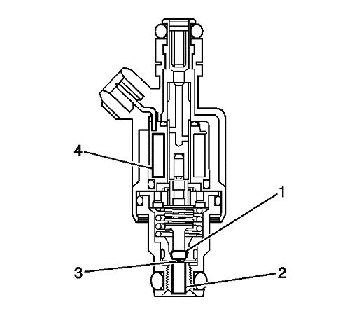
The fuel injector assembly is a solenoid device controlled by the control module that meters pressurized fuel to a single engine cylinder. The control module energises the high-impedance, 12 ohms, injector solenoid (4) to open a normally closed ball valve (1). This allows fuel to flow into the top of the injector, past the ball valve, and through a director plate (3) at the injector outlet. The director plate has machined holes that control the fuel flow, generating a spray of finely atomised fuel at the injector tip (2). Fuel from the injector tip is directed at the inlet valve, causing the fuel to become further atomised and vapourised before entering the combustion chamber. This fine atomisation improves fuel economy and emissions.
The control module monitors voltages from several sensors in order to determine how much fuel to give the engine. The control module controls the amount of fuel delivered to the engine by changing the fuel injector pulse width. The fuel is delivered under one of several modes.
The ECM supplies voltage to the fuel pump control module when the ECM detects that the ignition is ON. The voltage from the ECM to the fuel pump control module remains active for 2 s, unless the engine is in Crank or Run. While this voltage is being received, the fuel pump control module closes the ground switch of the fuel tank fuel pump module and also supplies a varying voltage to the fuel tank fuel pump module in order to maintain the desired fuel line pressure. The ECM calculates the air/fuel ratio based on inputs from the engine coolant temperature (ECT), manifold absolute pressure (MAP), mass air flow (MAF), and throttle position sensors. The system stays in starting mode until the engine speed reaches a predetermined RPM.
If the engine floods, the engine can be cleared by pressing the accelerator pedal down to the floor and then cranking the engine. When the throttle position sensor is at wide open throttle (WOT), the ECM reduces the fuel injector pulse width in order to increase the air to fuel ratio. The ECM holds this injector rate as long as the throttle stays wide open and the engine speed is below a predetermined RPM. If the throttle is not held wide open, the ECM returns to the starting mode.
The run mode has 2 conditions called Open Loop and Closed Loop. When the engine is first started and the engine speed is above a predetermined RPM, the system begins Open Loop operation. The ECM ignores the signal from the heated oxygen sensor (HO2S). The ECM calculates the air/fuel ratio based on inputs from the engine coolant temperature (ECT), manifold absolute pressure (MAP), mass air flow (MAF), and throttle position sensors. The system stays in Open Loop until meeting the following conditions:
| • | The HO2S has varying voltage output, showing that the HO2S is hot enough to operate properly. |
| • | The ECT sensor is above a specified temperature. |
| • | A specific amount of time has elapsed after starting the engine. |
Specific values for the above conditions exist for each different engine, and are stored in the electrically erasable programmable read-only memory (EEPROM). The system begins Closed Loop operation after reaching these values. In Closed Loop, the ECM calculates the air/fuel ratio, injector ON time, based upon the signal from various sensors, but mainly from the HO2S. This allows the air/fuel ratio to stay very close to 14.7:1.
When the driver pushes on the accelerator pedal, air flow into the cylinders increases rapidly. To prevent possible hesitation, the ECM increases the pulse width to the injectors to provide extra fuel during acceleration. This is also known as power enrichment. The ECM determines the amount of fuel required based upon throttle position, engine coolant temperature (ECT), manifold absolute pressure (MAP), mass air flow (MAF), and engine speed.
When the driver releases the accelerator pedal, air flow into the engine is reduced. The ECM monitors the corresponding changes in throttle position, mass air flow (MAF), and manifold absolute pressure (MAP). The ECM shuts OFF fuel completely if the deceleration is very rapid, or for long periods, such as long, closed-throttle coast-down. The fuel shuts OFF in order to prevent damage to the catalytic converters.
When the battery voltage is low, the ECM compensates for the weak spark delivered by the ignition system in the following ways:
| • | Increasing the amount of fuel delivered |
| • | Increasing the idle RPM |
| • | Increasing the ignition dwell time |
The ECM cuts OFF fuel from the fuel injectors when the following conditions are met in order to protect the powertrain from damage and improve driveability:
| • | The ignition is OFF. This prevents engine run-on. |
| • | The ignition is ON but there is no ignition reference signal. This prevents flooding or backfiring. |
| • | The engine speed is too high, above red line. |
| • | The vehicle speed is too high, above rated tyre speed. |
| • | During an extended, high speed, closed throttle coast down--This reduces emissions and increases engine braking. |
| • | During extended deceleration, in order to prevent damage to the catalytic converters |
The ECM controls the air/fuel metering system in order to provide the best possible combination of driveability, fuel economy, and emission control. The ECM monitors the heated oxygen sensor (HO2S) signal voltage while in Closed Loop and regulates the fuel delivery by adjusting the pulse width of the injectors based on this signal. The ideal fuel trim values are around 0 percent for both short and long term fuel trim. A positive fuel trim value indicates the ECM is adding fuel in order to compensate for a lean condition by increasing the pulse width. A negative fuel trim value indicates that the ECM is reducing the amount of fuel in order to compensate for a rich condition by decreasing the pulse width. A change made to the fuel delivery changes the long and short term fuel trim values. The short term fuel trim values change rapidly in response to the HO2S signal voltage. These changes fine tune the engine fuelling. The long term fuel trim makes coarse adjustments to fueling in order to re-center and restore control to short term fuel trim. A scan tool can be used to monitor the short and long term fuel trim values. The long term fuel trim diagnostic is based on an average of several of the long term speed load learn cells. The ECM selects the cells based on the engine speed and engine load. If the ECM detects an excessively lean or rich condition, the ECM will set a fuel trim diagnostic trouble code (DTC).
| © Copyright Chevrolet. All rights reserved |


