Captiva |
||||||||
|
|
|
|||||||
EN-42385-850 Thread Repair Kit
For equivalent regional tools, refer to Special Tools : LE5 or LE9 .
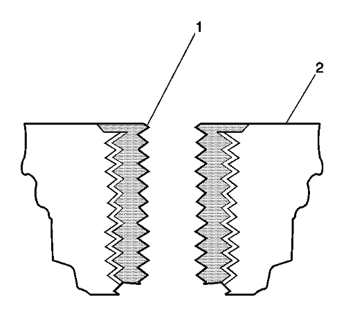
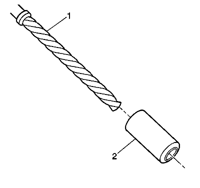
The thread repair process involves a solid, thin walled, self-locking, carbon steel, bush type insert (1). During the bush installation process, the driver tool expands the bottom external threads of the insert into the base material (2). This action mechanically locks the insert in place. Also, when installed to the proper depth, the flange of the insert will be seated against the counterbore of the repaired hole.
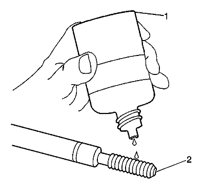
Note: The use of a cutting fluid, WD 40®, or equivalent, is recommended when performing the drilling, counterboring, and tapping procedures. Refer to Adhesives, Fluids, Lubricants, and Sealers .
Driver oil MUST be used on the installer driver tool. The tool kits are designed for use with either a suitable tap wrench or drill motor.| • | M6 inserts require a minimum drill depth of 15 mm (0.59 in). |
| • | M8 inserts require a minimum drill depth of 20 mm (0.79 in). |
| • | M10 inserts require a minimum drill depth of 23.5 mm (0.93 in). |
Warning: Refer to Safety Glasses and Compressed Air Warning in the Preface section.
| • | M6 inserts require a minimum tap depth of 15 mm (0.59 in). |
| • | M8 inserts require a minimum tap depth of 20 mm (0.79 in). |
| • | M10 inserts require a minimum tap depth of 23.5 mm (0.93 in). |
Warning: Refer to Safety Glasses and Compressed Air Warning in the Preface section.
Warning: Refer to Cleaning Solvent Warning in the Preface section.
Note: Do not allow oil or other foreign material to contact the outside diameter (OD) of the insert.
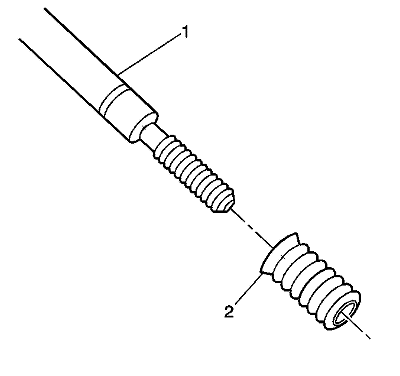
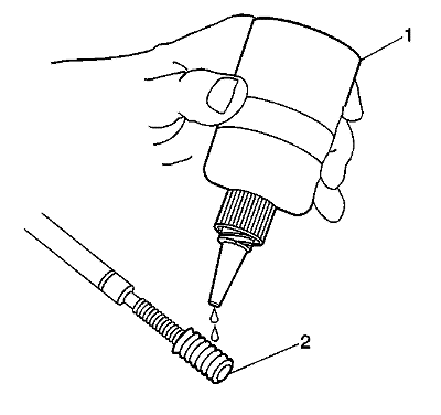
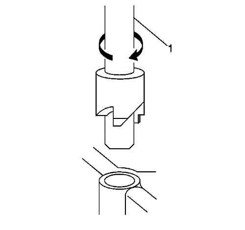
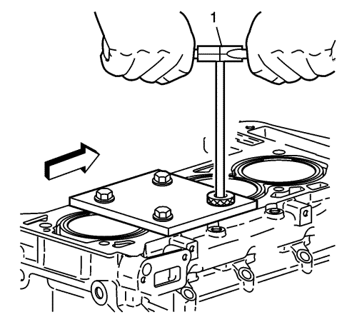
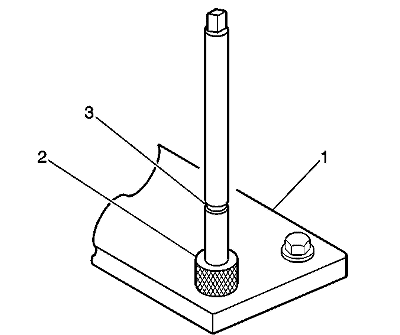
Install the insert until the flange of the insert contacts the counterbored surface. Continue to rotate the installer tool (1) through the insert.
The installer tool will tighten up before screwing completely through the insert. This is acceptable. You are forming the bottom threads of the insert and mechanically locking the insert to the base material threads.
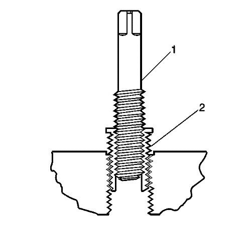
A properly installed insert (1) will be either flush or slightly below flush with the surface of the base material (2).
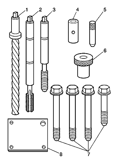
| • | Drill (1) |
| • | Tap (2) |
| • | Installer (3) |
| • | Sleeve (4) |
| • | Alignment Pin (5) |
| • | Bush (6) |
| • | Bolts (7) |
| • | Fixture Plate (8) |
Warning: Refer to Safety Glasses and Compressed Air Warning in the Preface section.
Note: The use of a cutting fluid, WD 40®, or equivalent, is recommended when performing the drilling and tapping procedures. Refer to Adhesives, Fluids, Lubricants, and Sealers .
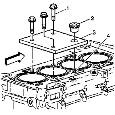
Driver oil MUST be used on the installer driver tool. The tool kits are designed for use with either a suitable tap wrench or drill motor.Position the fixture plate and bush over the hole that is to be repaired (4).

Note: During the reaming process, it is necessary to repeatedly remove the drill and clean the chips from the hole.
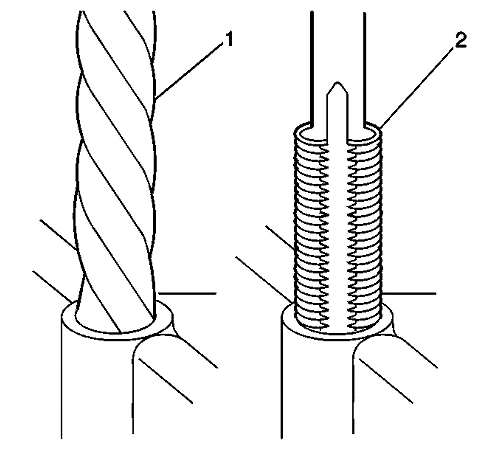
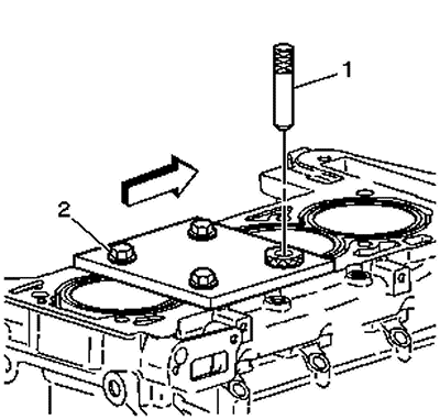
Drill the hole until the stop collar (1) of the drill bit or the sleeve contacts the bush.
Warning: Refer to Safety Glasses and Compressed Air Warning in the Preface section.
In order to tap the new threads to the proper depth, rotate the tap into the hole until the mark (3) on the tap aligns with the top of the drill bush (2).
Warning: Refer to Safety Glasses and Compressed Air Warning in the Preface section.
Warning: Refer to Cleaning Solvent Warning in the Preface section.
Note: Do not allow oil or other foreign material to contact the outside diameter (OD) of the insert.
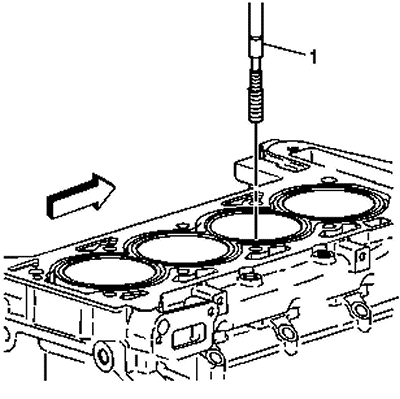
Rotate the driver tool until the mark on the tool aligns with the deck surface of the engine block.
The installer tool will tighten up before screwing completely through the insert. This is acceptable. You are forming the bottom threads of the insert and mechanically locking the insert to the base material threads.
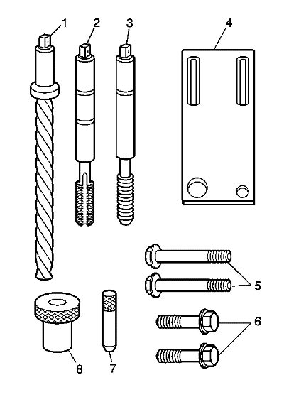
| • | Drill (1) |
| • | Tap (2) |
| • | Installer (3) |
| • | Fixture Plate (4) |
| • | Long Bolts (5) |
| • | Short Bolts (6) |
| • | Alignment Pin (7) |
| • | Bush (8) |
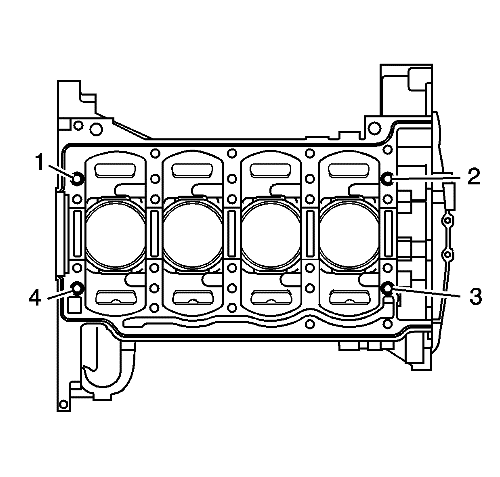
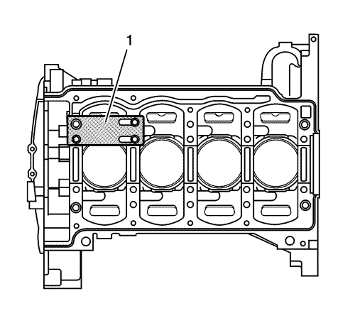
Position the fixture plate and bush over the hole that is to be repaired.
Warning: Refer to Safety Glasses and Compressed Air Warning in the Preface section.
In order to tap the new threads to the proper depth, rotate the tap into the hole until the mark (3) on the tap aligns with the top of the bush (2).
Warning: Refer to Safety Glasses and Compressed Air Warning in the Preface section.
Warning: Refer to Cleaning Solvent Warning in the Preface section.
Note: Do not allow oil or other foreign material to contact the outside diameter (OD) of the insert.
Note: The fixture plate and bush remain installed onto the engine block during the insert installation procedure.
Rotate the driver tool until the mark on the tool (3) aligns with the top of the bush (2).
The installer tool will tighten up before screwing completely through the insert. This is acceptable. You are forming the bottom threads of the insert and mechanically locking the insert to the base material threads.
| © Copyright Chevrolet. All rights reserved |


