Servo Unit Replacement — Right Hand Drive
Special Tools
CH 558-10 Closure Cap
For equivalent regional tools, refer to Special Tools .
Warning: Refer to Brake Fluid Irritant Warning in the Preface section.
Caution: Refer to Brake Fluid Effects on Paint and Electrical Components Caution in the Preface section.
Caution: When adding fluid to the brake fluid reservoir or to the clutch fluid reservoir, use only DOT-4+ brake fluid from a clean, sealed container. This polyglycol brake fluid is hygroscopic and absorbs moisture. Do not use fluid from an open container that may be contaminated with water. Improper or contaminated fluid could result in damage to the system components.
Removal Procedure
- Turn the ignition to the OFF position.
- Remove the air cleaner assembly. Refer to
Air Cleaner Assembly Replacement : LDE, LXV, LUW, 2H0 and LFH .
- Loosen steering gear tank remove bolt.
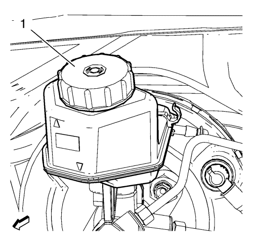
- Remove the brake fluid reservoir cap and install CH 558-10 cap (1) in order to prevent fluid loss and contamination.
Note: Cap the brake pipe fittings to prevent brake fluid loss and contamination.
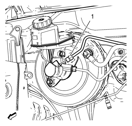
- Disconnect the master cylinder secondary brake pipe fitting (1).
Note: Cap the brake pipe fittings to prevent brake fluid loss and contamination.
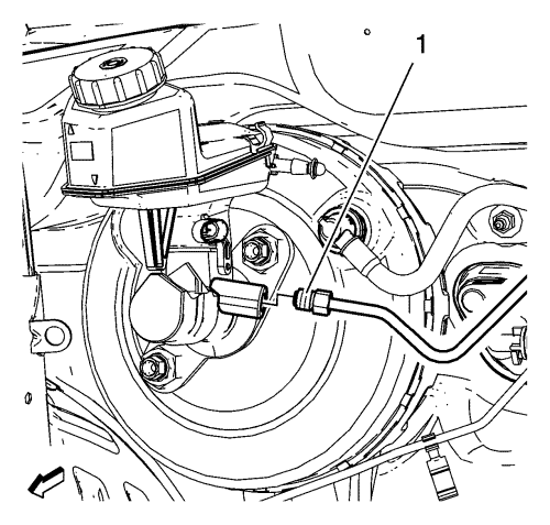
- Disconnect the master cylinder primary brake pipe fitting (1).
- Remove the brake master cylinder assembly from the booster. Refer to
Master Cylinder Replacement : Left Hand Drive → Right Hand Drive .
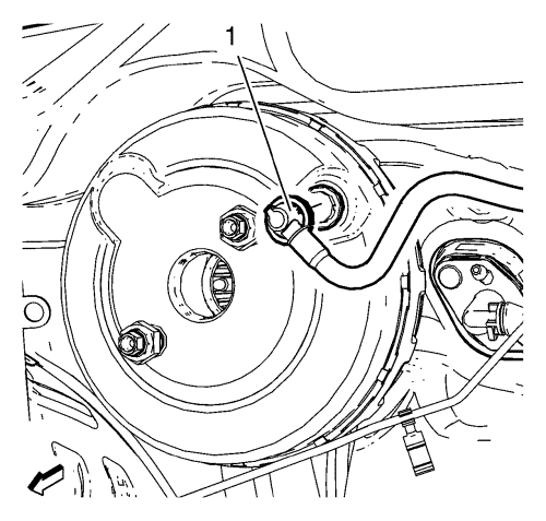
- Remove the booster vacuum pipe (1) from the booster.
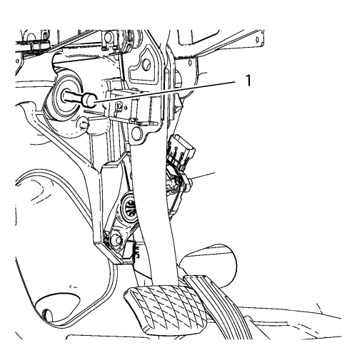
- Disconnect the brake pedal pushrod (1) from the brake pedal.
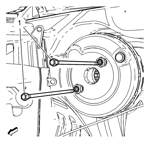
- Remove the brake booster bolts (1).
- Remove the booster from the vehicle.
Installation Procedure
- Install the booster to the vehicle.
Caution: Refer to Fastener Caution in the Preface section.
- Install the brake booster bolts (1) and tighten to 19 N·m (15 lb ft).
- Connect the brake pedal pushrod (1) to the brake pedal.
- Install the booster vacuum pipe (1) to the booster.
- Install the master cylinder assembly to the booster. Refer to
Master Cylinder Replacement : Left Hand Drive → Right Hand Drive .
- Connect the master cylinder primary brake pipe fitting (1) and tighten to 18 N·m (14 lb ft).
- Connect the master cylinder secondary brake pipe fitting (1) and tighten to 18 N·m (14 lb ft).
- Remove the CH 558-10 cap (1) and install the brake fluid reservoir cap.
- Install steering gear tank tighten bolt
- Install the air cleaner assembly. Refer to
Air Cleaner Assembly Replacement : LDE, LXV, LUW, 2H0 and LFH .
- Bleed the hydraulic brake system. Refer to Hydraulic Brake System Bleeding .
| © Copyright Chevrolet. All rights reserved |


