Master Cylinder Replacement - Right Hand Drive
Removal Procedure
Warning: Refer to Brake Fluid Irritant Warning in the Preface section.
Caution: Refer to Brake Fluid Effects on Paint and Electrical Components Caution in the Preface section.
Caution: When adding fluid to the brake fluid reservoir or to the clutch fluid reservoir, use only DOT-4+ brake fluid from a clean, sealed container. This polyglycol brake fluid is hygroscopic and absorbs moisture. Do not use fluid from an open container that may be contaminated with water. Improper or contaminated fluid could result in damage to the system components.
- Disconnect the brake fluid level indicator switch electrical connector and separate from brake fluid reservoir.
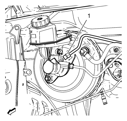
- Disconnect the master cylinder secondary brake pipe fitting (1).
Cap the brake pipe fitting and plug the master cylinder outlet port to prevent brake fluid loss and contamination.
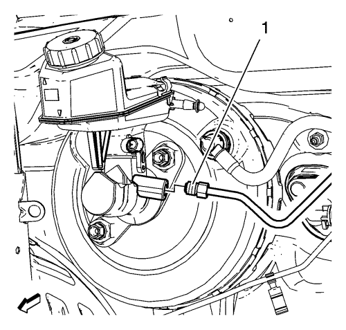
- Disconnect the master cylinder primary brake pipe fitting (1).
Cap the brake pipe fitting and plug the master cylinder outlet port to prevent brake fluid loss and contamination.
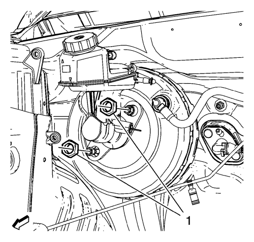
- Remove and DISCARD the master cylinder nuts (1).
- Remove master cylinder with brake fluid reservoir.
- Inspect the master cylinder to vacuum brake booster seal for damage and replace, if necessary.
- Remove the master cylinder reservoir, if necessary. Refer to Master Cylinder Reservoir Replacement .
Installation Procedure
- Install the brake fluid reservoir to master cylinder. Refer to Master Cylinder Reservoir Replacement .
- Bench bleed the master cylinder. Refer to Master Cylinder Bench Bleeding .
- Ensure the master cylinder to vacuum brake booster seal is properly seated on the master cylinder barrel.
Caution: Refer to Fastener Caution in the Preface section.
Caution: Refer to Torque-to-Yield Fastener Caution in the Preface section.
- Install NEW master cylinder nuts (1) and tighten to 50 N·m (37 lb ft).
- Connect the brake fluid level indicator switch electrical connector and install to the brake fluid reservoir.
- Connect the master cylinder primary brake pipe fitting (1) and tighten to 18 N·m (14 lb ft).
- Connect the master cylinder secondary brake pipe fitting (1) and tighten to 18 N·m (14 lb ft).
- Connect the brake fluid level indicator switch electrical connector.
- Bleed the hydraulic brake system. Refer to Hydraulic Brake System Bleeding .
| © Copyright Chevrolet. All rights reserved |


