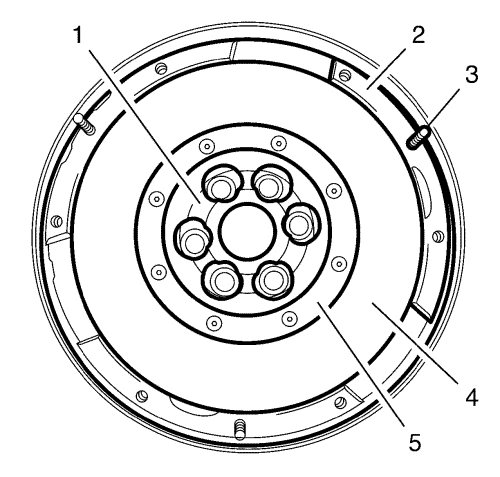
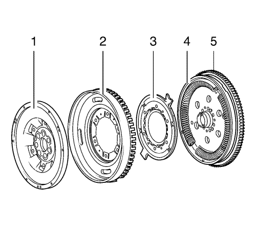
Through friction of clutch plate on the friction surface of the dual mass flywheel temperatures up to 200 °C can arise during normal driving. At sliding clutch or through operating errors much higher temperatures can arise. These temperatures must not cause mandatory a reduced lifetime of the dual mass flywheel.
If all other checkable features are OK, the dual mass flywheel can stay in the vehicle.
In these cases the dual mass flywheel has to be replaced.
All following checking procedures have to be carried out at installed dual mass flywheel. For visual vehicle checks a very bright light and an additional bright and small pocket lamp is necessary. Damage like grease on primary flywheel and loose ore missing balance weights cannot be checked at installed condition. During visual check material alteration can be stated which eliminates a further operating suitability.
For comparison different damages at dual mass flywheel with the corresponding further procedure are presented here.
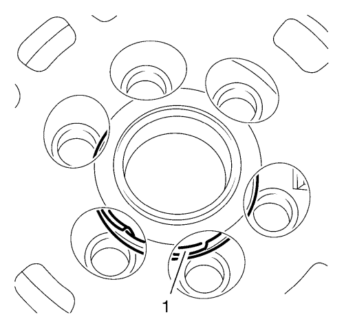
Note: In case of mechanical damages at plain bearing the dual mass flywheel has to be replaced.
- Inspect plain bearing (1) for damage.
Dependent of the manufacturer damages can be detected through ventilation openings of secondary flywheel. Parts of the bearing (1) are detached or lie loose around the bearing bolt.
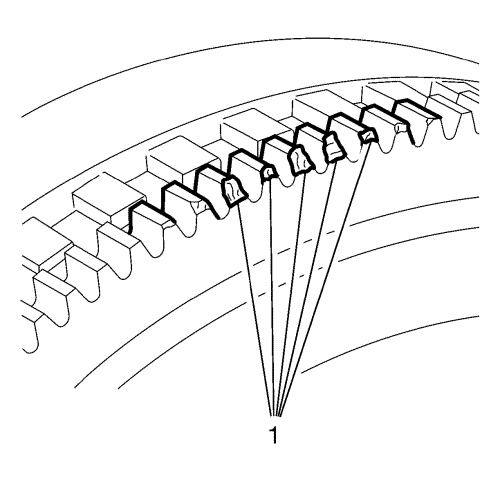
Note: Light abrasion on frontal areas of teeth is allowed. If problems occur during starting the engine the dual mass flywheel has to be replaced.
- Inspect toothed ring (1) for damage.
The toothed ring is needed to start the engine. Through a lot of starting procedures and/or an incorrect engaging starter signs of abrasion can occur on teeth of the toothed ring. The profile of damages can reach from only low signs of abrasion up to heavy material removal. The installation of a pulse-generator ring depends on the manufacturer.
The image shows signs of abrasion and mechanical damages at toothed ring (1), they occur through abrasion due to a lot of starting procedures. In this case the dual mass flywheel has to be replaced.
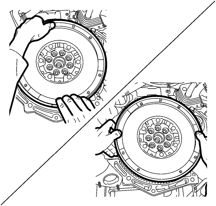
Note: The check must be carried out only by hand without any tools.
- Inspect tilt clearance.
At dual mass flywheel the additional-mass ring looms over the gap between primary and secondary flywheel. It is not possible to carry out just a visual check.
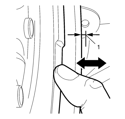
Note: An absolutely clear measurement is not possible with this check due to the different applied forces of the several workshop employees during the check.
- Grasp dual mass flywheel and apply thumbs onto the outer radius of secondary flywheel.
- Apply pressure onto the secondary flywheel alternating on upper, lower, left and right side
During the tilt clearance check a functional metal rattling noise may occur.
If tilt clearance is higher than 3 mm (MUST be measured, DO NOT make an estimation) (1) the dual mass flywheel has to be replaced.
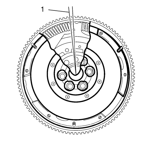
- Inspect clearance angle (1).
Before the inspection of the clearance angle the dual mass flywheel should be rotated several times clockwise and anticlockwise to receive a feeling for the resistance of the springs. In addition unusual loud clicking noise or possible rattle, crunch, grinding noise can be heard during rotation of the dual mass flywheel.
If the rotation of the flywheel is impossible the flywheel is defective and has to be replaced.
The clearance angle is the angle (1) about the secondary and the primary flywheel can be turned light against each other. Thereby the flange wings are moved in the duct of the bowed springs without adjoining the bowed springs. Dictated by functional factors the clearance angle is up to 8 teeth.
Is the secondary flywheel rotated beyond this point the bowed springs in the duct are moved to spring arrestor in the primary flywheel/cover. Now the spring force of the bowed springs is active.
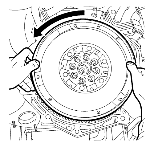
| • | Rotate secondary flywheel anticlockwise (arrow) until the elastic counterforce (spring force) is clear noticeable. |
| • | Release secondary flywheel slowly until the bowed springs are relaxed, so no counterforce acts onto the springs. |
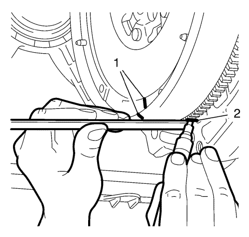
| • | Mark position with a vertical line using a white pencil on secondary flywheel (1) and on toothed ring for starter (2). |
| • | Rotate secondary flywheel clockwise until the elastic counterforce is clearly noticeable. |
| • | Release secondary flywheel slowly until the bowed springs are relaxed. |
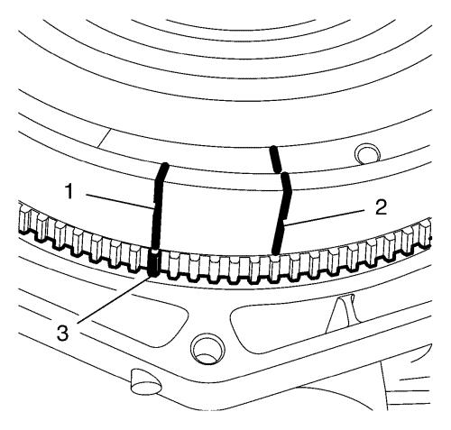
| • | Apply new marking on secondary flywheel (1) on the height of the marking on the toothed ring for starter (3). |
| • | Count amount of teeth on toothed ring for starter from marked tooth up to the height of the first marking on secondary flywheel (2). Dictated by functional factors up to 8 teeth are allowed. |
- ALWAYS replace the engine flywheel if following conditions are given:
| • | The difference exceeds the amount of 8 teeth. |
| • | The dual mass flywheel cannot be rotated. |
| • | During rotating the dual mass flywheel a hard metallic arrestor is audible or noticeable. |
