Orlando
Engine Control Module Wiring Harness Replacement — 1.6 LDE, LXV, 1.8L 2H0
Removal Procedure
Disconnect the battery negative cable. Refer to
Battery Negative Cable Disconnection and Connection
:
without Start/Stop System
.
Raise and support the vehicle. Refer to
Lifting and Jacking the Vehicle
.
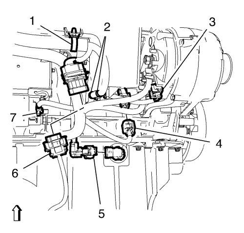
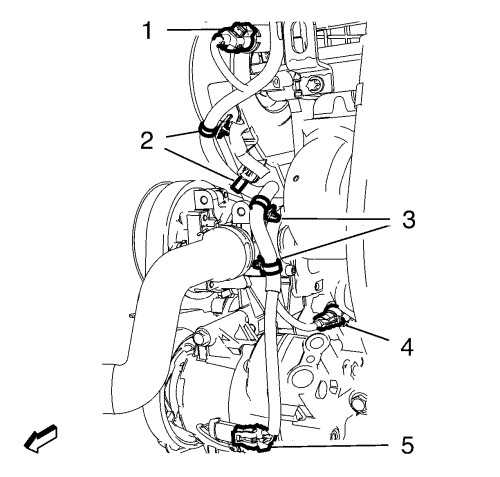
If equipped, disconnect the engine oil level sensor wiring harness plug (5).
Disconnect the alternator wiring harness plug (3).
Remove the starter positive cable nut (7) and remove the starter positive cable.
Unclip the heated oxygen sensor connection from the bracket and disconnect the heated oxygen sensor wiring harness plug (6).
Disconnect the knock sensor wiring harness plug (4).
Unclip the 3 wiring harness clips (1, 2) from the intake manifold. Hang the wiring harness aside.
Lower the vehicle.
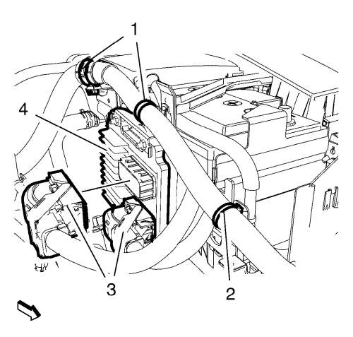
Disconnect the 2 engine control module wiring harness plugs (3) from the engine control module (4).
Unclip the 3 wiring harness clips (1, 2) from the engine control module wiring harness brackets.
Remove the engine control module bracket along with the engine control module in top direction from the battery tray.
Remove the battery tray. Refer to
Battery Tray Replacement
.
Remove the front compartment fuse block. Refer to
Front Compartment Fuse Block Replacement
.
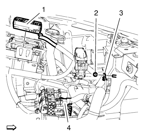
Remove the wiring harness ground cable nut (2) and remove the wiring harness ground cable (3).
Remove the wiring harness plug (1) in top direction from the front compartment fuse block housing.
Disconnect the wiring harness connection adaptor plug (4).
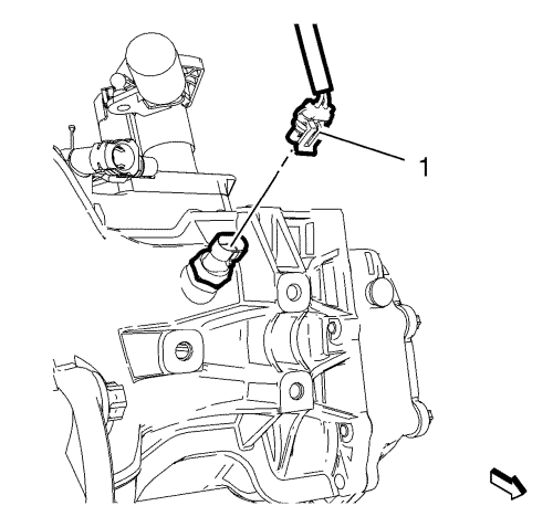
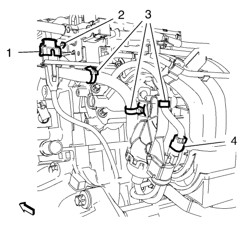
Disconnect the reversing light switch wiring harness plug (1).
Disconnect the air conditioning compressor wiring harness plug (5).
Disconnect the engine oil pressure indicator switch wiring harness plug (4).
Unclip the 4 wiring harness plugs (2, 3) from the brackets.
Disconnect the exhaust camshaft position actuator solenoid valve (1).
Disconnect the mass air flow sensor wiring harness plug (2) and unclip the wiring harness clip in top direction from the air cleaner housing.
Disconnect the intake camshaft position actuator solenoid valve wiring harness plug (3).
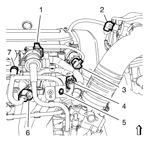
Disconnect the evaporate emission canister purge valve wiring harness plug (1).
Disconnect the throttle body wiring harness plug (4) and the manifold absolute pressure sensor wiring harness plug (6).
Unclip the wiring harness clips (5, 7) from the brackets.
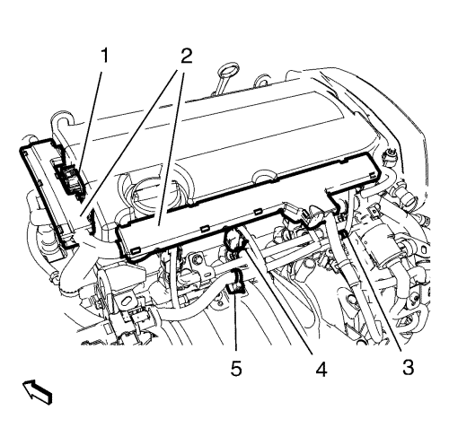
Disconnect the intake manifold tuning valve actuator check valve wiring harness plug (4).
Disconnect the crankshaft position sensor wiring harness plug (1).
Unclip the 4 wiring harness clips (2, 3) from the brackets.
Disconnect the heated oxygen sensor wiring harness plug (7).
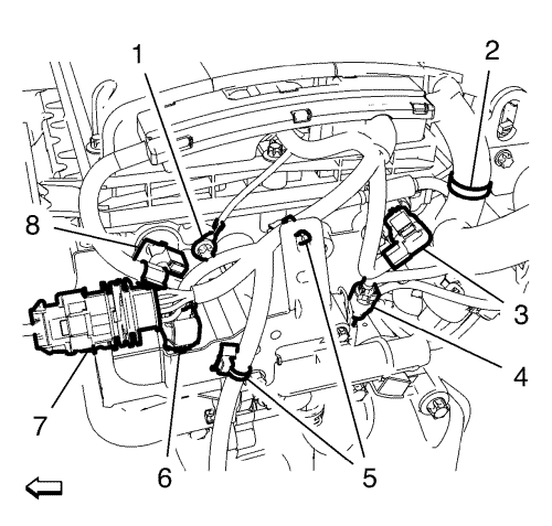
Disconnect the coolant thermostat wiring harness plug (6) and disconnect the 2 camshaft position sensor wiring harness plugs (3, 8).
Disconnect the engine coolant temperature sensor wiring harness plug (4).
Unclip the 3 wiring harness clips (2, 5) from the wiring harness brackets.
Remove the wiring harness ground bolt (1) and remove the wiring harness ground cable.
Unclip the 2 engine wiring harness clips (3, 5) from the brackets.
Unclip the 2 engine wiring harness conduits (2) in top direction from the camshaft cover.
Disconnect the ignition coil wiring harness plug (1) and disconnect the 4 injector wiring harness plugs (4).
Remove the engine control module wiring harness from the vehicle.
Installation Procedure
Position the engine control module wiring harness to the vehicle.
Connect the ignition coil wiring harness plug (1) and connect the 4 injector wiring harness plugs (4).
Clip the 2 engine wiring harness conduits (2) to the camshaft cover.
Clip the 2 engine wiring harness clips (3, 5) to the brackets.
Caution:
Refer to
Fastener Caution
in the Preface section.
Install the wiring harness ground cable and the wiring harness ground cable bolt (1) and tighten to
8 N·m (71 lb in)
.
Clip the 3 wiring harness clips (2, 5) to the wiring harness brackets.
Connect the engine coolant temperature sensor wiring harness plug (4).
Connect the coolant thermostat wiring harness plug (6) and connect the 2 camshaft position sensor wiring harness plugs (3, 8).
Connect the heated oxygen sensor wiring harness plug (7).
Clip the 4 wiring harness clips (2, 3) to the brackets.
Connect the crankshaft position sensor wiring harness plug (1).
Connect the intake manifold tuning valve actuator check valve wiring harness plug (4).
Clip the wiring harness clips (5, 7) to the brackets.
Connect the throttle body wiring harness plug (4) and the manifold absolute pressure sensor wiring harness plug (6).
Connect the evaporate emission canister purge valve wiring harness plug (1).
Connect the intake camshaft position actuator solenoid valve wiring harness plug (3).
Connect the mass air flow sensor wiring harness plug (2) and clip the wiring harness clip to the air cleaner housing.
Connect the exhaust camshaft position actuator solenoid valve (1).
Clip the 4 wiring harness plug (2, 3) to the brackets.
Connect the engine oil pressure indicator switch wiring harness plug (4).
Connect the air conditioning compressor wiring harness plug (5).
Connect the reversing light switch wiring harness plug (1).
Connect the wiring harness connection adaptor plug (4).
Install the wiring harness plug (1) to the front compartment fuse block housing.
Install the wiring harness ground cable (3) and install the wiring harness ground cable nut (2) and tighten to
9 N·m (80 lb in)
.
Install the front compartment fuse block. Refer to
Front Compartment Fuse Block Replacement
.
Install the battery tray. Refer to
Battery Tray Replacement
.
Install the engine control module bracket along with the engine control module to the battery tray.
Connect the 2 engine control module wiring harness plugs (3) to the engine control module (4).
Clip the 3 wiring harness clips (1, 2) to the engine control module wiring harness brackets.
Raise the vehicle.
Clip the 3 wiring harness clips (1, 2) to the intake manifold.
Connect the knock sensor wiring harness plug (4).
Clip the heated oxygen sensor connection to the bracket and connect the heated oxygen sensor wiring harness plug (6).
Install the starter positive cable and the starter positive cable nut (7) and tighten to
12.5 N·m (111 lb in)
.
Connect the alternator wiring harness plug (3).
If equipped, connect the engine oil level sensor wiring harness plug (5).
Lower the vehicle.
Connect the battery negative cable. Refer to
Battery Negative Cable Disconnection and Connection
:
without Start/Stop System
.
© Copyright Chevrolet. All rights reserved