Orlando
Intake Manifold Insulator Replacement
Removal Procedure
Disconnect the battery negative cable. Refer to
Battery Negative Cable Disconnection and Connection
:
without Start/Stop System
.
Remove the intake manifold cover. Refer to
Intake Manifold Cover Replacement
.
Remove the throttle body assembly. Refer to
Throttle Body Assembly Replacement
.
Unclip the radiator surge inlet hose/pipe from the fuel rail.
Remove the brake booster vacuum pipe from the intake manifold.
Remove the oil level indicator tube. Refer to
Oil Level Indicator Tube Replacement
.
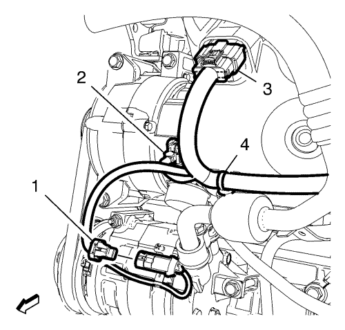
Disconnect the ECM wiring harness plug (3) from the fuel injector wiring harness plug.
Raise and support the vehicle. Refer to
Lifting and Jacking the Vehicle
.
Disconnect the generator wiring harness plug (2) and the A/C compressor wiring harness plug (1).
Unclip the wiring harness clip (4) from the intake manifold bracket.
Disconnect the knock sensor wiring harness plug.
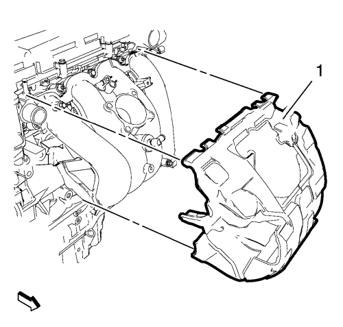
Pull the intake manifold insulator over the lower intake manifold brackets.
Lower the vehicle completely.
Remove the intake manifold insulator (1).
Installation Procedure
Install the intake manifold insulator (1).
Raise the vehicle.
Pull the intake manifold insulator over the lower intake manifold brackets.
Connect the knock sensor wiring harness plug.
Connect the alternator wiring harness plug (2).
Lower the vehicle.
Connect the ECM wiring harness plug (3) to the fuel injector wiring harness.
Connect the generator wiring harness plug (2) and the A/C compressor wiring harness plug (1).
Clip in the wiring harness clip (4) to the intake manifold bracket.
Install the oil level indicator tube. Refer to
Oil Level Indicator Tube Replacement
.
Install the brake booster vacuum pipe to the intake manifold.
Clip the radiator surge inlet hose/pipe to the fuel rail.
Install the throttle body assembly. Refer to
Throttle Body Assembly Replacement
.
Install the inlet manifold cover. Refer to
Intake Manifold Cover Replacement
.
Connect the battery negative cable. Refer to
Battery Negative Cable Disconnection and Connection
:
without Start/Stop System
.
© Copyright Chevrolet. All rights reserved