To the top of the document
Nubira-Lacetti
To Previous Page To Next Page
GMDE Start Page Load static TOC Load dynamic TOC Help?


SECTION 3

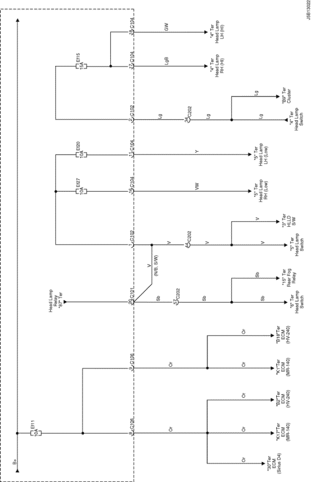
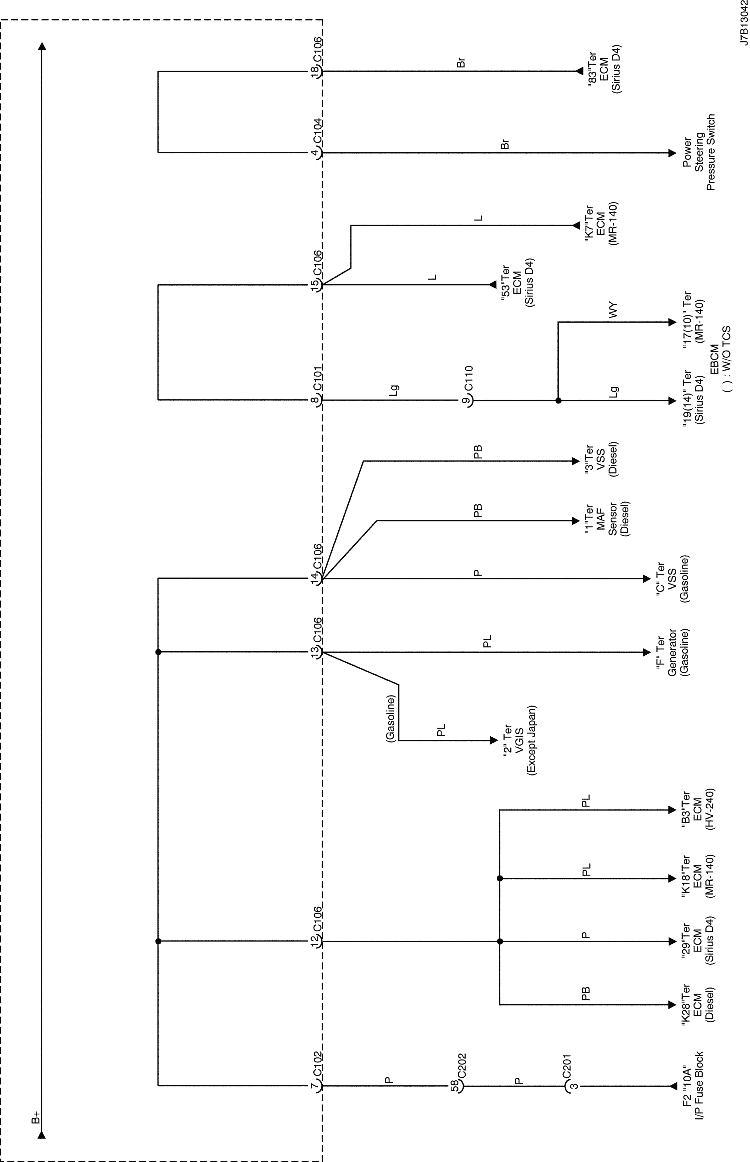
WIRING DIAGRAM FOR POWER SUPPLIES


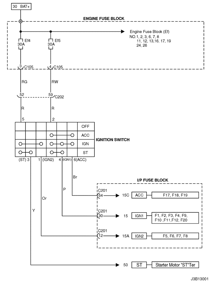
1. IGNITION SWITCH CIRCUIT

J3B13001.png
Display graphicTranslations of text in graphics


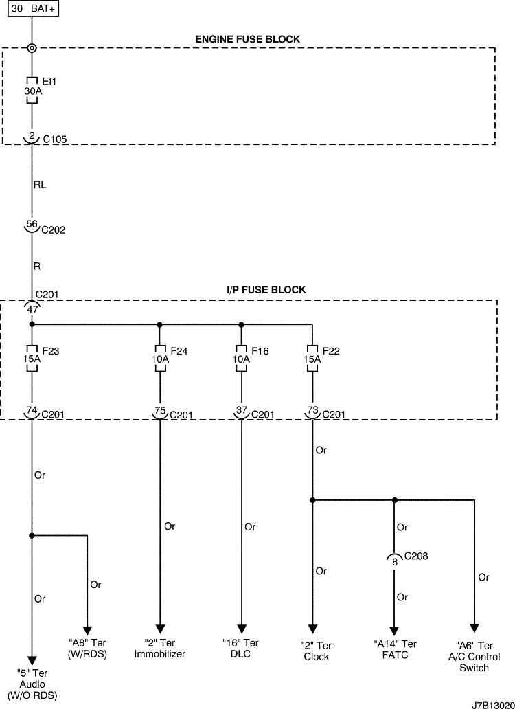
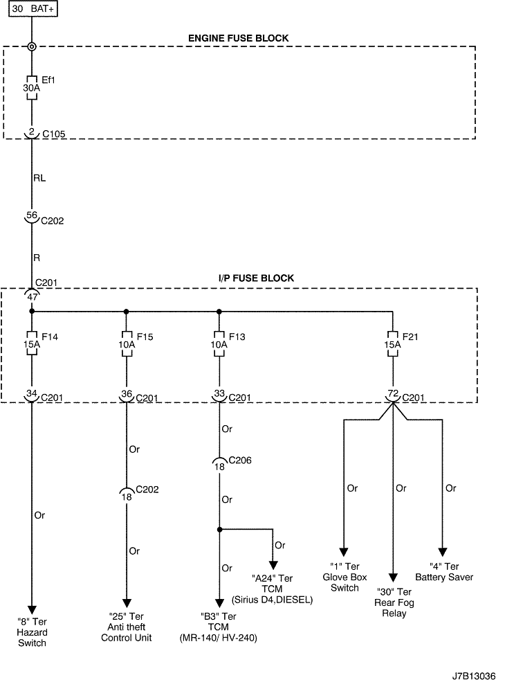
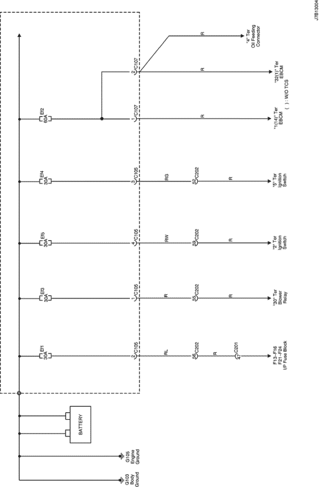
2. 30 TER "BAT+" POWER SUPPLY CIRCUIT (I.P FUSE BLOCK)

J7B13020.png
Display graphicTranslations of text in graphics


J7B13036.png
Display graphicTranslations of text in graphics


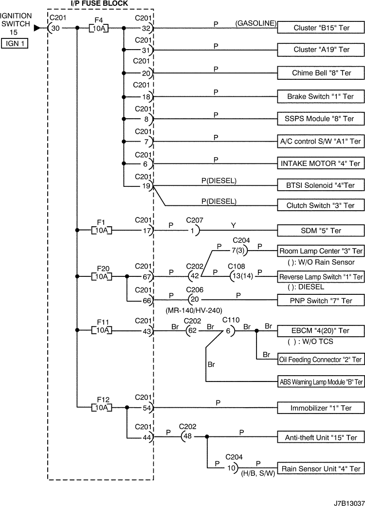
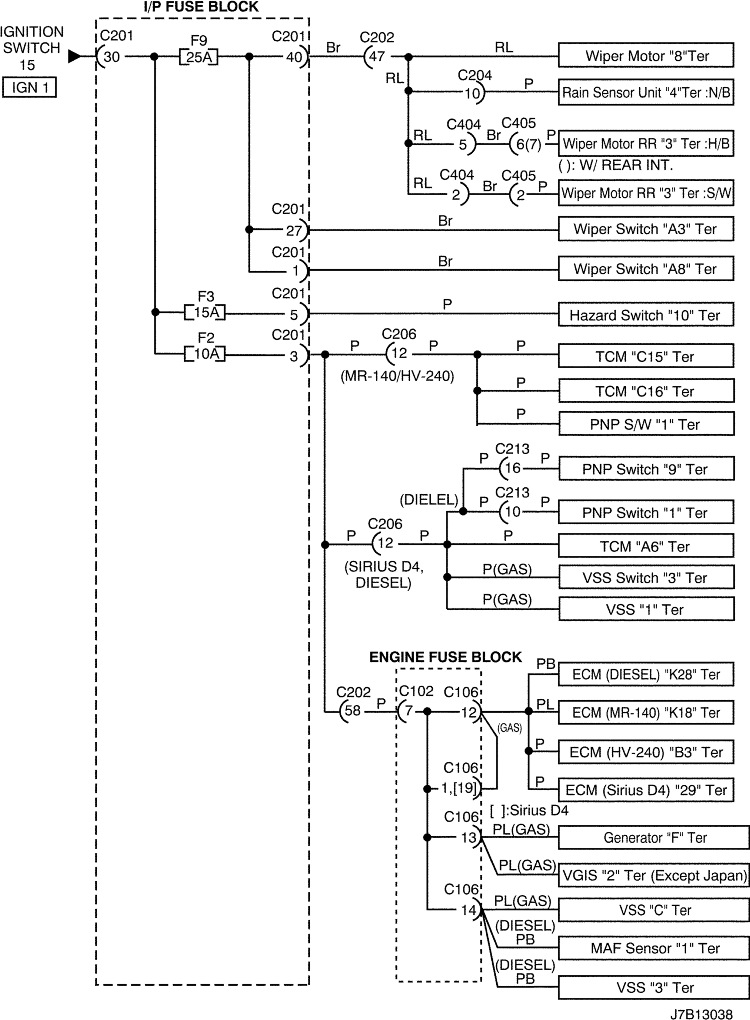
3. 15 TER "IGN1" POWER SUPPLY CIRCUIT (I.P FUSE BLOCK)

J7B13037.png
Display graphicTranslations of text in graphics


J7B13038.png
Display graphicTranslations of text in graphics


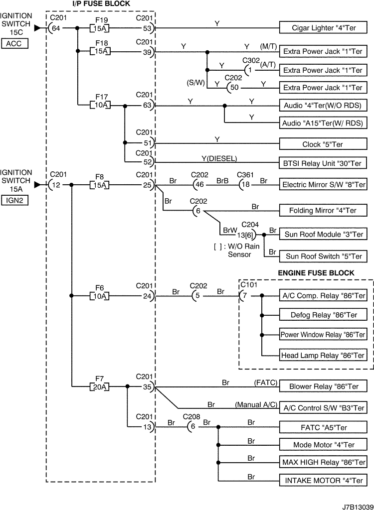
4. 15A TER "IGN2", 15C TER "ACC" POWER SUPPLY CIRCUIT (I.P FUSE BLOCK)

J7B13039.png
Display graphicTranslations of text in graphics


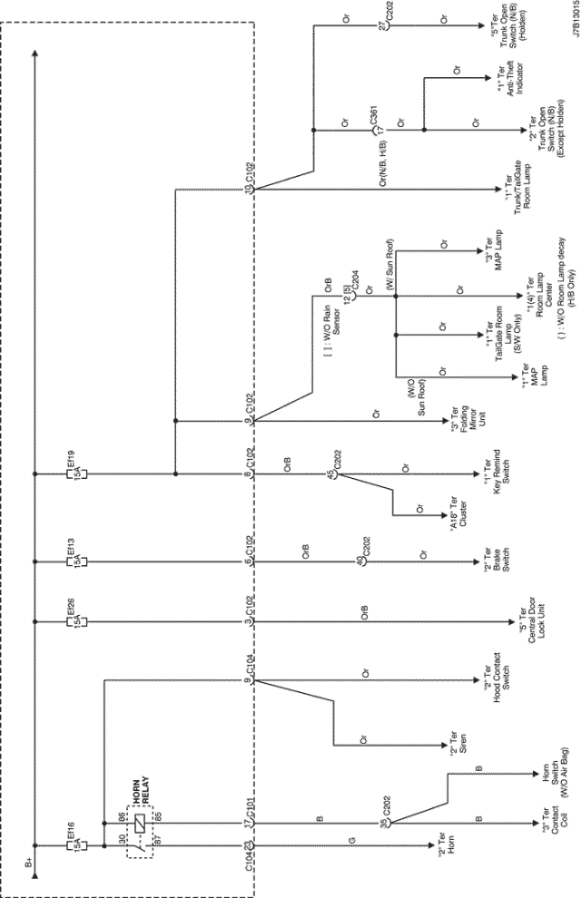
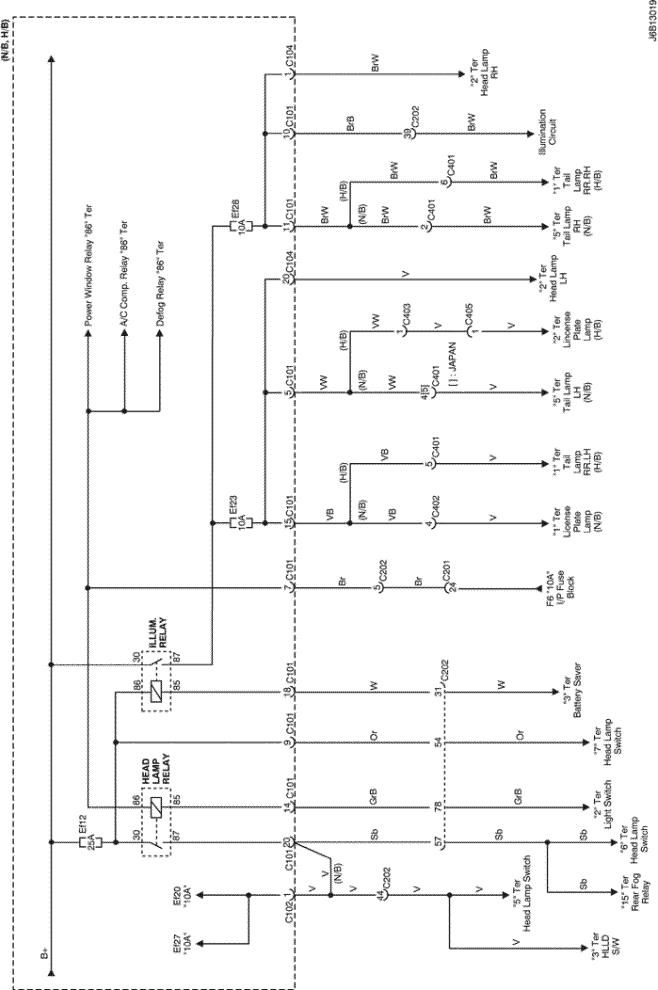
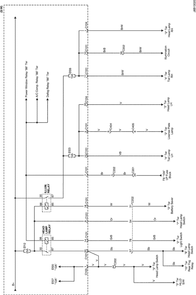
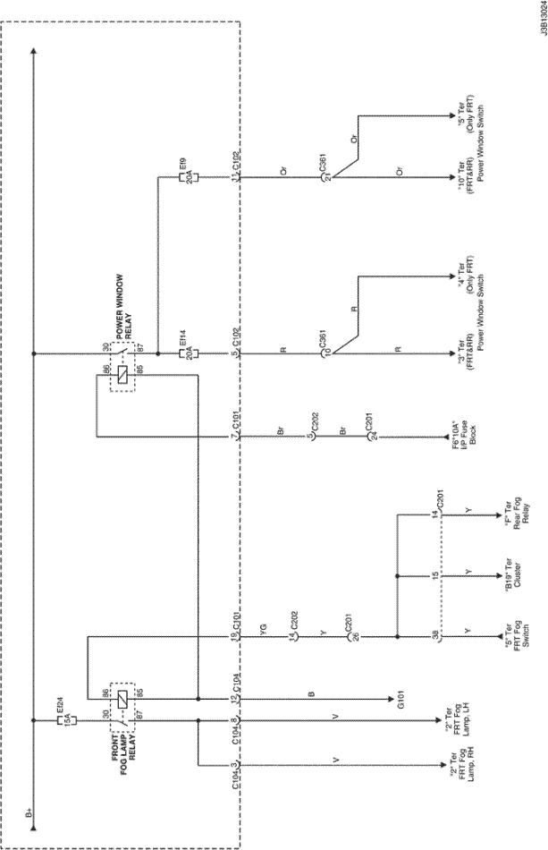
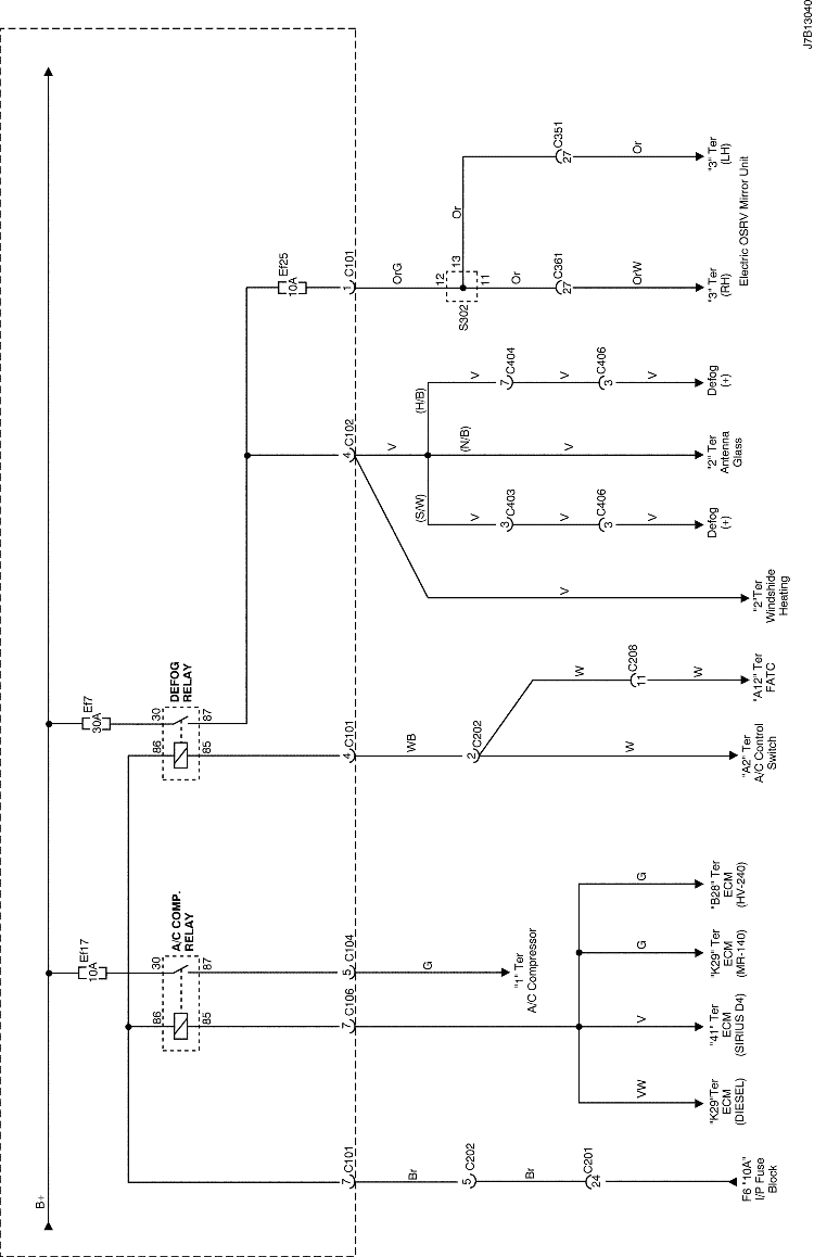
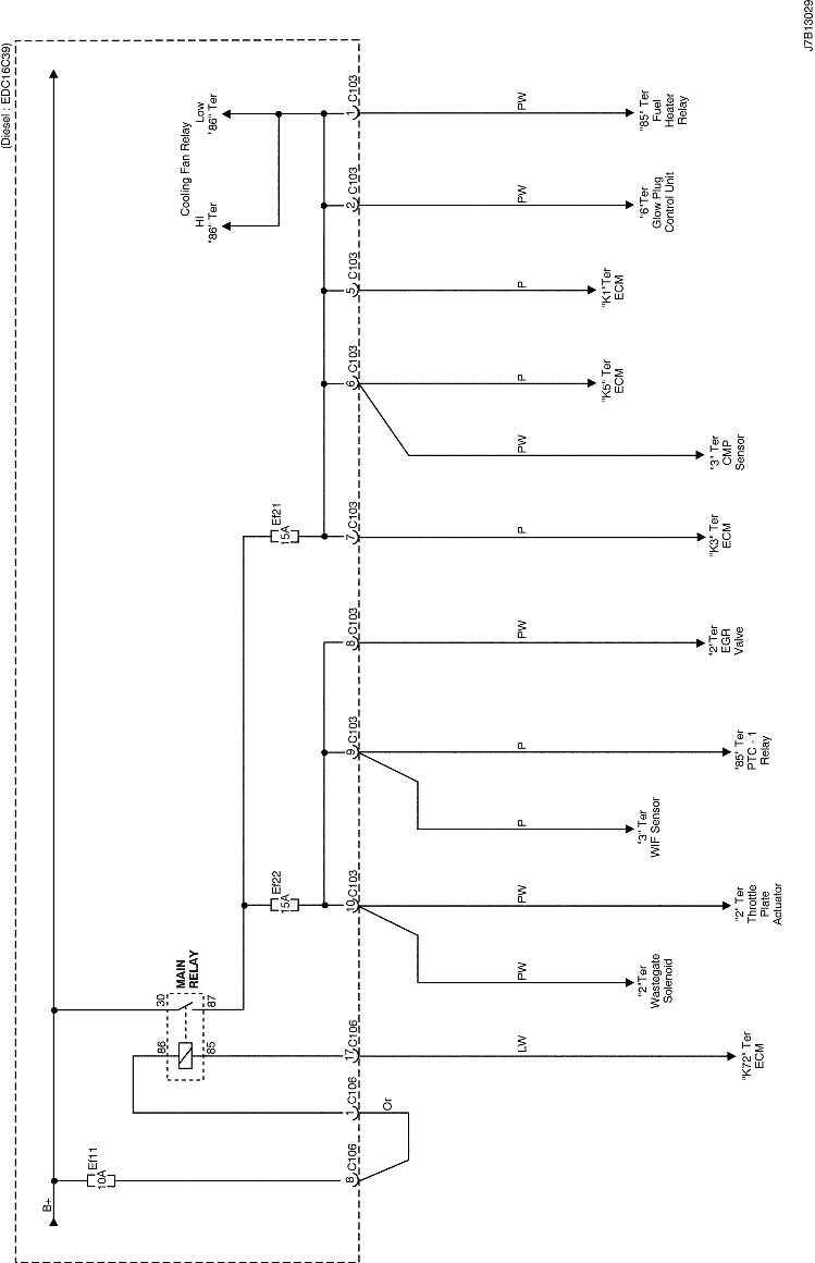
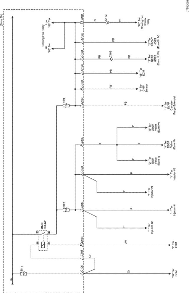
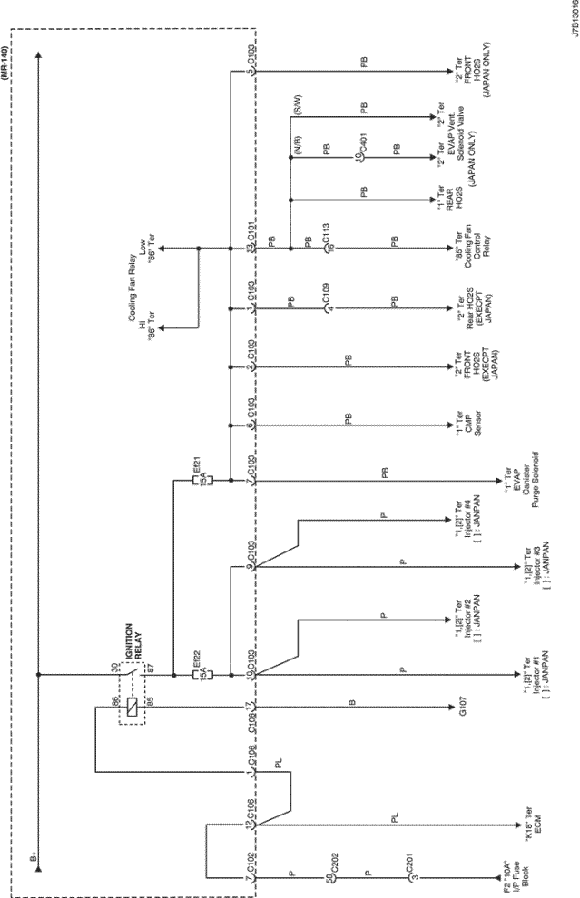
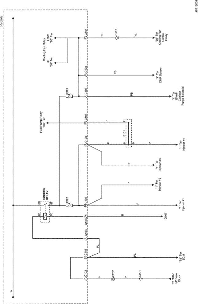
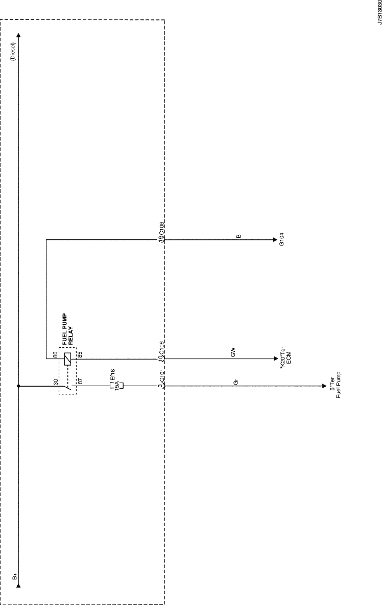
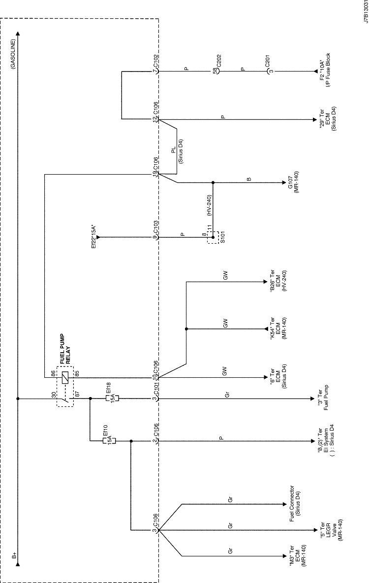
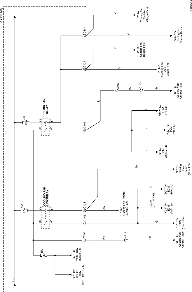
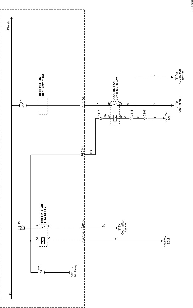
5. ENGINE FUSE BLOCK & RELAY CIRCUIT

J7B13004.png
Display graphicTranslations of text in graphics


J7B13015.png
Display graphicTranslations of text in graphics


J6B13019.png
Display graphicTranslations of text in graphics


J6B13020.png
Display graphicTranslations of text in graphics


J3B13024.png
Display graphicTranslations of text in graphics


J7B13040.png
Display graphicTranslations of text in graphics


J7B13029.png
Display graphicTranslations of text in graphics


J7B13008.png
Display graphicTranslations of text in graphics


J7B13016.png
Display graphicTranslations of text in graphics


J7B13009.png
Display graphicTranslations of text in graphics


J7B13030.png
Display graphicTranslations of text in graphics


J7B13031.png
Display graphicTranslations of text in graphics


J7B13045.png
Display graphicTranslations of text in graphics


J7B13043.png
Display graphicTranslations of text in graphics


J5B13022.png
Display graphicTranslations of text in graphics


J7B13042.png
Display graphicTranslations of text in graphics


To Previous Page To Next Page


© Copyright Chevrolet Europe. All rights reserved