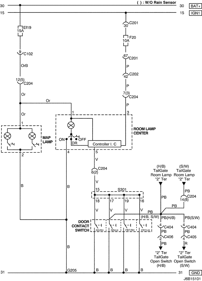
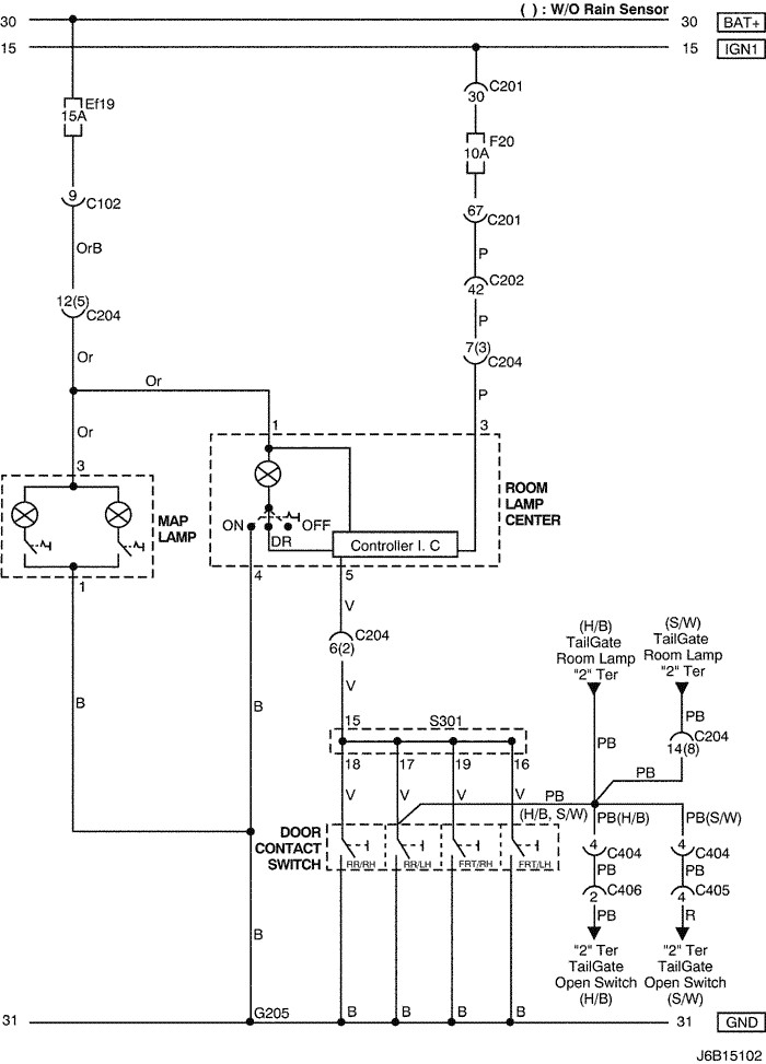
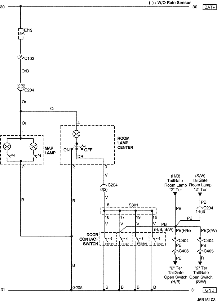
20. LAMP (MAP & ROOM) CIRCUIT
1) W/O SUN ROOF & W/ DECAY
a. CONNECTOR INFORMATION
CONNECTOR NO
(PIN NO, COLOR) |
CONNECTING WIRING HARNESS |
CONNECTOR POSITION |
| C102 (11 Pin, White) |
Body – Engine Fuse Block |
Engine Fuse Block |
| C201 (76 Pin, Black) |
I.P – I.P Fuse Block |
I.P Fuse Block |
| C202 (89 Pin, White) |
I.P – Body |
Left CO-Driver Leg Room |
| C204 (14 Pin, White) |
Roof – Body (W/ Rain Sensor) |
Left CO-Driver Leg Room |
| C204 (8 Pin, White) |
Roof – Body (W/O Rain Sensor) |
Left CO-Driver Leg Room |
| C404 (8 Pin, White) |
T/Gate. EXT. - Body |
Inside Left C Pillar |
| C405 (8 Pin, White) |
T/Gate. EXT. - T/Gate |
Beside Left Rear Wiper Motor |
| C406 (6 Pin, White) |
T/Gate. EXT. - T/Gate |
Beside Left Rear Wiper Motor |
| S301 (Blue) |
Body |
Left CO-Driver Leg Room |
| G205 |
Roof |
Inside CO-Driver A Pillar |
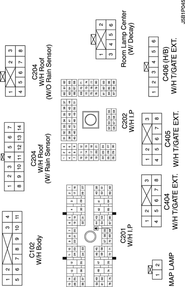
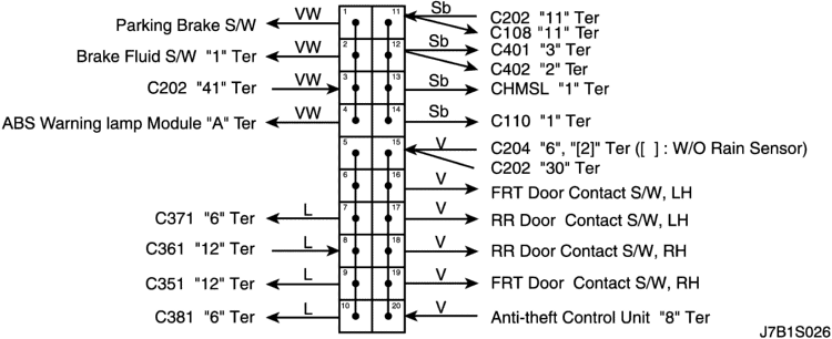
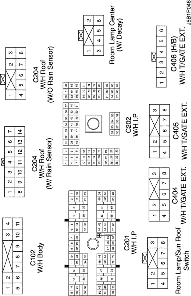
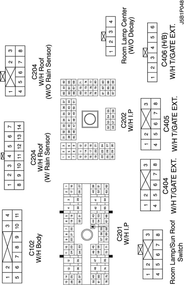
b. CONNECTOR IDENTIFICATION SYMBOL & PIN NUMBER POSITION
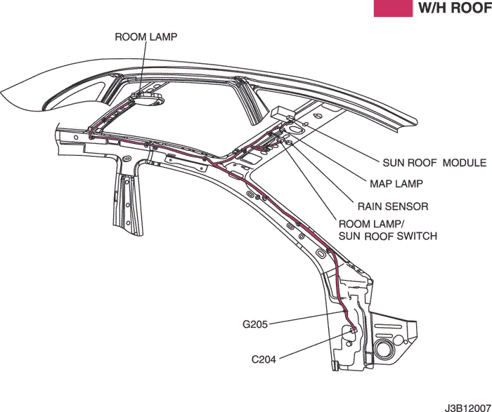
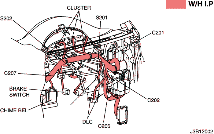
c. POSITION OF CONNECTORS AND GROUNDS
d. SPLICE PACK
S301 (NOTCH BACK)
S301 (HATCH BACK)
S301 (STATION WAGON)
2) W/ SUN ROOF & W/ DECAY
a. CONNECTOR INFORMATION
CONNECTOR NO
(PIN NO, COLOR) |
CONNECTING WIRING HARNESS |
CONNECTOR POSITION |
| C102 (11 Pin, White) |
Body – Engine Fuse Block |
Engine Fuse Block |
| C201 (76 Pin, Black) |
I.P – I.P Fuse Block |
I.P Fuse Block |
| C202 (89 Pin, White) |
I.P – Body |
Left CO-Driver Leg Room |
| C204 (14 Pin, White) |
Roof – Body (W/ Rain Sensor) |
Left CO-Driver Leg Room |
| C204 (8 Pin, White) |
Roof – Body (W/O Rain Sensor) |
Left CO-Driver Leg Room |
| C404 (8 Pin, White) |
T/Gate. EXT. - Body |
Inside Left C Pillar |
| C405 (8 Pin, White) |
T/Gate. EXT. - T/Gate |
Beside Left Rear Wiper Motor |
| C406 (6 Pin, White) |
T/Gate. EXT. - T/Gate |
Beside Left Rear Wiper Motor |
| S301 (Blue) |
Body |
Left CO-Driver Leg Room |
| G205 |
Roof |
Inside CO-Driver A Pillar |
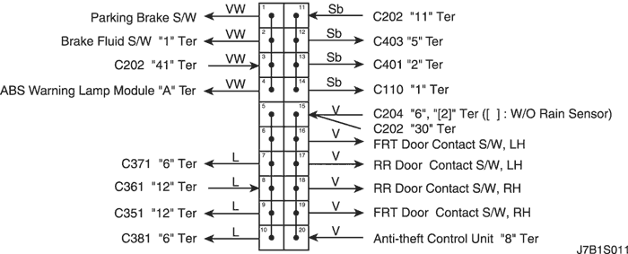
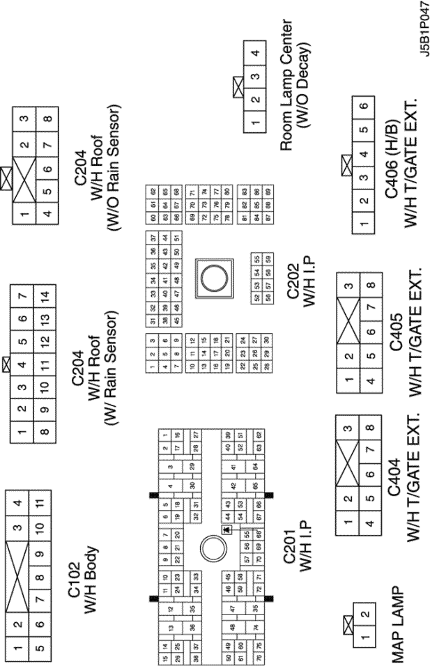
b. CONNECTOR IDENTIFICATION SYMBOL & PIN NUMBER POSITION
c. POSITION OF CONNECTORS AND GROUNDS
d. SPLICE PACK
S301 (NOTCH BACK)
S301 (HATCH BACK)
S301 (STATION WAGON)
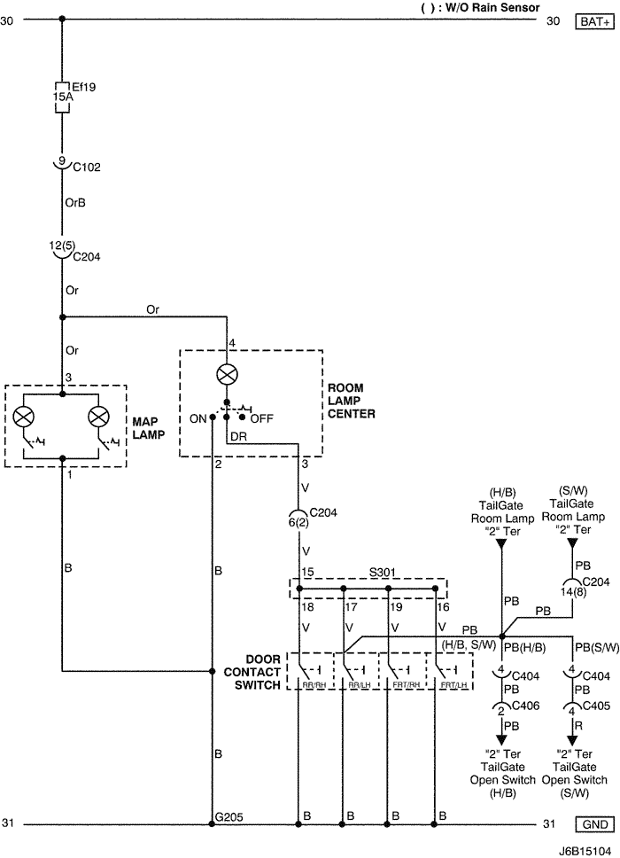
3) W/O SUN ROOF & W/O DECAY
a. CONNECTOR INFORMATION
CONNECTOR NO
(PIN NO, COLOR) |
CONNECTING WIRING HARNESS |
CONNECTOR POSITION |
| C102 (11 Pin, White) |
Body – Engine Fuse Block |
Engine Fuse Block |
| C201 (76 Pin, Black) |
I.P – I.P Fuse Block |
I.P Fuse Block |
| C202 (89 Pin, White) |
I.P – Body |
Left CO-Driver Leg Room |
| C204 (14 Pin, White) |
Roof – Body (W/ Rain Sensor) |
Left CO-Driver Leg Room |
| C204 (8 Pin, White) |
Roof – Body (W/O Rain Sensor) |
Left CO-Driver Leg Room |
| C404 (8 Pin, White) |
T/Gate. EXT. - Body |
Inside Left C Pillar |
| C405 (8 Pin, White) |
T/Gate. EXT. - T/Gate |
Beside Left Rear Wiper Motor |
| C406 (6 Pin, White) |
T/Gate. EXT. - T/Gate |
Beside Left Rear Wiper Motor |
| S301 (Blue) |
Body |
Left CO-Driver Leg Room |
| G205 |
Roof |
Inside CO-Driver A Pillar |
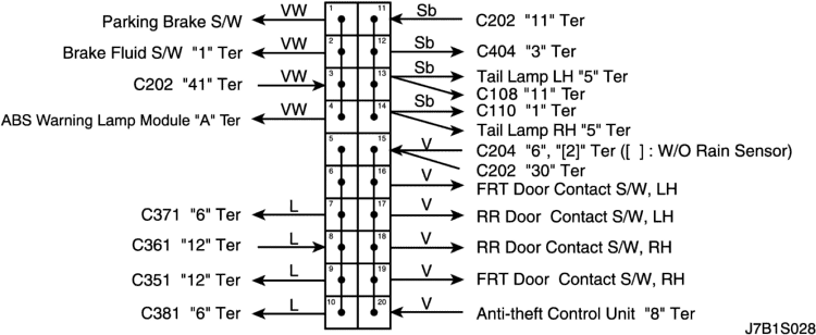
b. CONNECTOR IDENTIFICATION SYMBOL & PIN NUMBER POSITION
c. POSITION OF CONNECTORS AND GROUNDS
d. SPLICE PACK
S301 (NOTCH BACK)
S301 (HATCH BACK)
S301 (STATION WAGON)
4) W/ SUN ROOF & W/O DECAY
a. CONNECTOR INFORMATION
CONNECTOR NO
(PIN NO, COLOR) |
CONNECTING WIRING HARNESS |
CONNECTOR POSITION |
| C102 (11 Pin, White) |
Body – Engine Fuse Block |
Engine Fuse Block |
| C201 (76 Pin, Black) |
I.P – I.P Fuse Block |
I.P Fuse Block |
| C202 (89 Pin, White) |
I.P – Body |
Left CO-Driver Leg Room |
| C204 (14 Pin, White) |
Roof – Body (W/ Rain Sensor) |
Left CO-Driver Leg Room |
| C204 (8 Pin, White) |
Roof – Body (W/O Rain Sensor) |
Left CO-Driver Leg Room |
| C404 (8 Pin, White) |
T/Gate. EXT. - Body |
Inside Left C Pillar |
| C405 (8 Pin, White) |
T/Gate. EXT. - T/Gate |
Beside Left Rear Wiper Motor |
| C406 (6 Pin, White) |
T/Gate. EXT. - T/Gate |
Beside Left Rear Wiper Motor |
| S301 (Blue) |
Body |
Left CO-Driver Leg Room |
| G205 |
Roof |
Inside CO-Driver A Pillar |
b. CONNECTOR IDENTIFICATION SYMBOL & PIN NUMBER POSITION
c. POSITION OF CONNECTORS AND GROUNDS
d. SPLICE PACK
S301 (NOTCH BACK)
S301 (HATCH BACK)
S301 (STATION WAGON)
| © Copyright Chevrolet Europe. All rights reserved |